When it comes to making an FM receiver it's always thought to be a complex design, however the one transistor simple FM receiver circuit explained here simply shows that it isn't the case after all. Here a single transistor acts as a receiver, demodulator, amplifier to constitute a wonderful tiny FM radio.
It's basically based on a superregenerative audion receiver circuit where the use of minimal components becomes the main feature of the unit.
However fewer components also means a few compromises involved, here the receiver requires a large metal base for grounding the unwanted signals, and for keeping the noise factor to the lowest, and also this system would work only in places where the reception is rather strong and thus may not be suitable in areas where the signal strength is thinner.
Audio Video Representation
How the One Transistor FM Radio Receiver Works
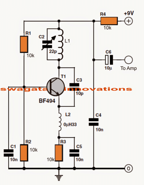
As mentioned above, the circuit is basically a single transistor superregenerative RF oscillator with a constant amplitude.
Here we have tried to enhance the design such that the amplitude becomes considerably magnified in order to turn OFF the transistor completely during the oscillations.
This called for an increase in the feedback capacitor and also to use a transistor specifically designed for handling extreme high frequency ranges such as a BF494.
Further modifications include an inductor with the emitter of the transistor, and a capacitor across the emitter resistor of the transistor.
Due to this the transistor is switched ON as soon as the base emitter voltage of the transistor falls significantly, resulting in an abrupt cut off in the oscillations.
However this prompts the emitter capacitor to discharge, allowing the collector current to yet again resume its flow, initiating a fresh cycle of oscillation.
The above happening forces the circuit to flip flop between two situations, oscillator OFF and oscillator ON, resulting a sawtooth frequency of about 50kHz at the output.
Each time the circuit flips across the above ON/OFF states, results in a significant stepping up of the amplitude which in turn constitutes greater amplification of the received signals. The procedure also gives rise to noise but only as long as a station is not being detected.
The above design has one drawback, though. The output received from the above circuit would have greater content of sawtooth noise compared to the actual FM reception.
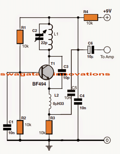
A smart technique can be seen employed in the following single transistor FM radio circuit to attribute better efficiency to this simple design.
Here we pull out the emitter capacitor C5 ground link and connect it with the output.
This results in a fall in the collector voltage as the collector current rises, which in turn forces the emitter voltage to rise, prompting the emitter capacitor to negate the situation at the output.
This enforcement results in making the sawtooth effect on the received signal practically to zero, thus presenting an FM audio with much reduced background noise.
Single Transistor Radio with Audio Amplifier
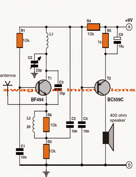
To make the above circuit self-contained, an additional transistor stage may be introduced for enabling the radio to play the music loudly over a small loudspeaker.
The circuit is self explanatory, just the inclusion of a general purpose BC559 transistor along with a few inexpensive passive components can be witnessed in the design.
How to Make the Inductors
The involved coils or the inductors are very simply to wind.
L1 which is the oscillator coil is an air cored inductor, meaning no core is required, wire is super enamelled type, 0.8mm in thickness, diameter of 8mm, with five turns.
L2 is wound over R6 itself using 0.2mm super enameled copper wire with 20 turns.
How to Set Up the Circuit
- Initially when the circuit is switched ON, the output will be accompanied with substantial background noise which will gradually tend to disappear on detection of am FM station.
- This may be done by carefully tuning C2 with the help of an insulated screwdriver.
- Try to keep the tuning at the edge of the band of the particular FM station, with some practice and patience this would get easier with time.
- Once tuned, the circuit would respond to that reception every time its switched without the need for further alignment.
- As indicated at the beginning of the article, the circuit should be installed over a wide circular meta plate, preferably a solderable material, and all the ground of the circuit soldered on this plate.
- This is important to keep the circuit stable and avoid drifting away of the received stations and also for cancelling unwanted noise.
- The antenna in the proposed single transistor FM radio receiver circuit is not crucial and in fact should be kept as small as possible, a 10cm wire would be just enough.
Remember, the circuit also acts a like an effective transmitter circuit, therefore keeping the antenna size bigger would mean transmitting noise across the ether and disturbing your neighbors radio reception.
The upside being that the design can also used as a walkie talkie within a small radial distance....more on this next time.
Smallest One Transistor FM Radio Receiver Circuit
Parts List
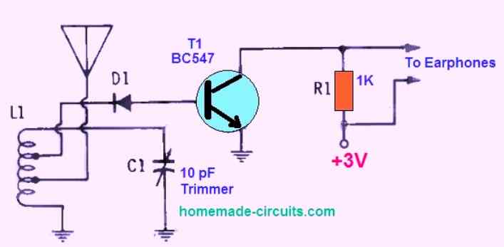
- C1 = 10 pf variable trimmer capacitor.
- D1 = 1N82 diode.
- L1 = 5 turns using No. 16 magnet wire wound on a 3/4 -inch diameter coil former, 1/2 inch long. It should be tapped at 1/2 turn from the ground side for connecting the antenna, and tapped 2 turns from top of coil for connecting the diode.
- T1 = BC547 transistor.
- R1 = 1K 1/4 watt 5% resistor.
- Earphone (magnetic)
This is a fascinating small single transistor FM receiver that, unbelievably, can tune the full 88-108 MHz FM music band while still producing enough energy to power a typical set of magnetic earbuds.
The tiny receiver is so small that it could be integrated into an empty cigarette pack. This tiny FM receiver can additionally catch the audio paths of some television channels.
How to Setup
The only challenging aspect is really the L/C circuit, that comprises of a 10-pf trimmer capacitor and a tapped antenna coil connected in parallel.
After completing L1 winding, test the circuit first. Try flipping the taps on the coil if you are having trouble hearing the FM stations.
If you're still having trouble, try experimenting a little with the coil by adjusting the taps a fraction of a turn at a time, individually, while attentively listening via the headphones and tweaking C1 with each adjustment you make.
Antenna Specifications
Just about any length of strong (whip-like) No. 10 or No. 12 wire could be used for the antenna. However we discovered that 3 and 1/8 inches worked best for the middle of the f-m band.
If the indicated 1N82 diode cannot be found, any other vhf diode could be used instead.
Other diodes like the OA91 work well at this frequency as well.
If magnetic earbuds are used, which we advise, simply remove R1 from the circuit.
Single IC Small FM Radio Circuit
If you are looking for an FM radio circuit which should be as small as possible yet have a very high accuracy in terms of band selection, then you can try the following concept.
It uses a single chip TDA7000 for the modulation and demodulation of the FM stations, and uses the IC LM386 for amplifying the captured audio signals.
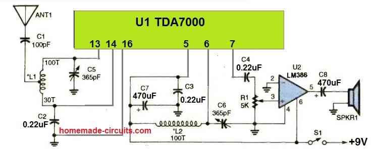
Everything in this single chip FM radio circuit looks straightforward except the two inductors. The two inductors L1 and L2 can be built in the following manner.
Both the coils have 100 turns and uses 28 SWG super enameled copper wire. Coil L1 has a center tap exactly at the midway of the 100 turns, that is at the 50th turn.



Questions & Answers
i have two questions:
1) HOW Smallest One Transistor FM Radio Receiver Circuit DEMUDULATE SIGNAL?
2) Can i change bf494 with 2n2222A or bc547c?
thank you.
Hello I built this circuit, but I used a 2N2222 instead of the BF transistor, and it doesn’t work. I don’t have the original transistor; the only transistor I have is a 2N2222. Can I use the 2N2222 instead, and what changes should I make to the circuit
Hey, technically 2N2222 should also work, but I would recommend using BF494 since it is a specialized RF transistor, and suitable for radio applications. Remember, the above circuits will only work only if the signal is strong enough and close to your location, it will not catch far away weaker signals.
The circuit uses slope detection then envelope detection. That LC coil and trimmer capacitor is tuned little bit side of the main station frequency, so it changes frequency to amplitude change. Then diode D1 cuts the half signal, and transistor base filters out the high radio frequency. Only audio signal stays, then it makes it louder for earphone.
Yes, you can use both. Actually diagram already showing BC547, but it is low power for high frequency FM. 2N2222A is much better option for RF work. But you must check the legs before solder, because BF494, BC547, and 2N2222A all have different E-B-C pin connection.
i meant if i can change bf494 with 2n2222a at single transistor radio(with audio amplifier) which is above smallest one transistor… thank you very much
Yes, you can use it..
just one more: one second shematic there is no r6 but you said the L2 is on r6. do i need to add r6 and other extra resisitors if i dont want a amplifier, or just make it without resisitor R6 and others thats appear on amplifier version? thank you!
R6 is present in the 3rd diagram, please check the 3rd diagram, so it is required only for the 3rd configuration…
Hello, sorry if this is a silly question, but I’m curious : will Smallest One Transistor FM Radio Receiver Circuit work with high impedance crystal earphones, diode 1N60 and 265pF variable capacitor (maybe changing the coil?). How this circuit demodulate signal?
Hey, sorry, no, the 265pF variable capacitor and the crystal earphone might not work for that FM radio circuit.
thank you sir for this circuits. This is beautiful self-quenching superregenerator. I remade it into forced quenching and it started working even better.
Thank you Eugene, that sounds great, if possible please send a 10 second video clip of your result, to my email ID..
homemadecircuits
@gmail.com
Ok, but please wait a little bit. I listen to the receiver through audio preamplifier and highohmic earphones.
Sure, no worries, please take your time…
It is nice explanation.
I am school science maths teacher later I become a telecom tech and worked in srilanka and
Dubai.
Lot of circuits they dont mention diameter of the coil wounding pipe.
even it is air cored one we have to use a pipe.
example a pensil etc or hand made one.
Also in this circuits if stage not there.
I hope it is required for AM circuits only.
Anyway I like transistir FM circuits.
So if you can publish powerful transistor circuits it is useful to the whole world.
Also can we use this knowledge for home buisness purpose
I am 73 years man.
Now no job no pension no children no wife no job.
Living alone but I am active man not idle person
I study chemistry, physics, maths and electronics.
So time passing no problem.
I am interested to make old fashion radios even it is big very nice
how to find casing for that can you guide me.
my e mail is ptrickperera@gmail.com
Thank you Patrick, for your interest in AM FM radio circuits.
I myself normally use a 3mm or 4mm drill bit to wind the coils.
10.7 MHz IF stage is utilized in FM radios also, so yes IF stage is required in FM radios also.
Yes, you can use any of the circuits from this blog for commercial purpose or for home business.
Here’s a link which has a handful of old fashioned radio circuits which you can try:
https://www.homemade-circuits.com/tuned-radio-frequency-receiver-trf-circuits/
For the casing you can try searching on amazon, eBay etc…
Let me know if you have any further doubts or questions, I will try to help!
You have given a very good article for the budding experimenter. Congratulations. However, there is one circuit that I think must be in error component wise. That is the Single IC Small FM Radio Circuit with the TDA7000. You show the coils as 100 turns and the variable capacitor as 365 pF. These would be typical values for an AM radio, but I can not imagine them working in the FM range.
Thanks so much for your kind words! Glad you liked it.
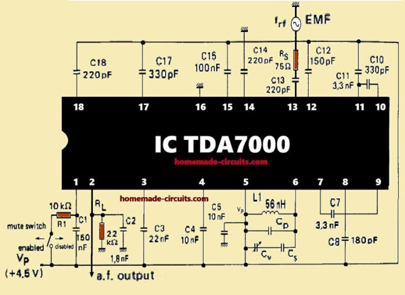
You are absolutely correct! An FM radio coil cannot have a coil of 100 turns, and a 365pF tuning capacitor… it seems to be a modified AM radio circuit, not an FM radio.
Here’s the actual TDA7000 based circuit taken from the datasheet of the IC. Make L1 = 56nH (2 or 3 turns, 5mm dia)
Connect 33pF or 47pF across it (CP). Put a 10pF cap in parallel (CW). Then add a trimmer capacitor (10 to 30pF range) to fine tune.
Acel circuit cu TDA 7000 este pentru AM, unde medii. Daca se analizeaza mai bine schema interna a circuitului TDA7000 se va observa ca sunt folosite numai anumite blocuri din el, numai acelea cu care poate functiona in AM. Deci nu va functiona in FM chiar cu acele date aratate de tine.
Hi Swag
Thanks for such a lot of really useful information. Just a question on the ‘Smallest One Transistor FM Radio Receiver Circuit’ – is the coil close-wound or loose-wound (L1 = 5 turns using No. 16 magnet wire wound on a 3/4 -inch diameter coil former, 1/2 inch long)? Although, I suppose when you say 1/2 inch long, that means it’s fairly close-wound.
Many thanks, Peter
Thanks Peter,
Yes, it is close wound, and the wire thickness does not need to be thicker than 1 mm, according to me.
bonjour,
radio FM base TDA7000
L1 – L2 , 100 tours sur quel diamètre ??
Remerciements
Acel radio este pentru unde medii, AM. Diametrul conductorului este de cca 0.35mm iar bobina se va efectua pe bara de ferita din circuitul de intrare (cea cu priza), de cca 10mm diametru.
Hi,
the diameter of the coil is not specified in the schematic. But based on common FM radio designs, a practical coil diameter for 100 turns using 28 SWG wire is typically around 4 mm to 6 mm.
”a practical coil diameter for 100 turns using 28 SWG wire is typically around 4 mm to 6 mm” Is not tipical for FM.
Merci pour l’info
très cordialement
I’m looking for a way to adjust the phase of one antenna to match the phase of a second antenna for max signal.
Variable indicators and capacitors.
Sorry, I don’t think I have this circuit design with me at the moment…
salve sign swagatam sono un tecnico elettronico italiano siccome dovrei realizzare un semplice ricevitore radio in FM con 2 transistor e nel web ne ho trovati ma con risultati deludenti vorrei che pubblicasse un o schema o diversi schemi elettrici allo scopo grazie giuseppe
Salve Giuseppe, te la mando io la schema con il ricevitore FM con un transistore BF199 come ricevitore e poi amplificatore audio a 3 transistori (BC547) gli ultimi due con la conessione galvanica…Tutto a baso voltaggio da 1.2volt fino a 1.5v .
Mi troverete tutii dal Italia qui : yo.el.yo@protonmail.com
You can publish my email address. You have my consent. Thank you.
Hi giuseppe,
A two transistor FM radio will only work for radio strong FM radio stations which are nearby, it will not not be able to catch distant FM stations.
The third circuit from top is a tested design, you can try it.
Actually I want to know some details remote control coordination pls
Good day sir. There was an FM transmitter designed by you using bc547 and um66 and other passive components as remote control transmitter, while already-made radio was the receiver to trigger cd4017 to trigger relay to off/on a load. I want to ask, can this FM receiver using bf494 and bc559 get the signal from the transmitter
of um66 and bc547 designed by you? Thanks
Hello Emmanuel, I guess you are referring to the following post:
https://www.homemade-circuits.com/how-to-make-fm-remote-control-using-fm/
You will get a much higher range if you use an actual FM radio for the above design, the range can be more than 30 meters. However using the single transistor version as the radio receiver, the range can be hardly 10 meters.
Sir, I don’t understand. Does it mean that the one transistor bf494, bc559 fm receiver can’t get the signal from bc547, um66- based FM transmitter(fm remote Tx) up to 30 meters?
Yes that’s correct! A proper FM radio has so many parts and sophisticated circuitry which makes it highly sensitive, that’s why its range will be more, whereas the single transistor FM radio is a crude form of FM radio so naturally its sensitivity and range will be much less than a full fledged radio.
Sir i don`t have BF494 transistor. So can i use others like 2N3904, BC547 2N2222 ……?
I think BC547 should work, you can try it.
Hi Swagatam,you mentioned that you are a manufacturer,what do you manufacture?
Hi Daniel, I used to manufacture automobile electronic products a few years ago but now I have discontinued it.
Sir….we r working on this project…….sir….why did u used 2 transistors….sir..? Is they r mandatory….but the concept itself is a fm radio with a single transistor…?…na sir…
Hello Sruthi, only the last diagram has two transistors rest all are single transistor. The extra transistor in the last diagram is for amplification so that a loudspeaker can be added in the design
God bless you sir .keep up the good work
Thank you for the quick response sir.pls since this circuit cannot transmit subwoofer signal ,can you please suggest me a better circuit to use instead?
You are welcome Muhammad, you can try the following transmitter circuit instead:
Make this Wireless Speaker Circuit
However, for the receiver you will have to use a small FM radio.
Hi sir, God bless you with this wonderful job u doing . Pls I want to know if I can use this circuit to make a wireless subwoofer?that is the receiver will be enlocsed in the sub woofer box.
And can bc547 be used instead of bf494?
Thank you Muhammad, I don’t think this circuit can be used for transmitting sub woofer signals, since the quality of the transmission may not be of H-Fi quality.
Hi !
Where can we get 400 ohm speaker my friend ? I’ve never seen such value of Speaker so far. Or ,instead, can we connect it any amplificator? Thanks in advance.
You can try a 100 ohm speaker, or simply connect an LM386 type amplifier with an 8 ohm speaker, or you can also try any of these transistorized small amplifier
Hi Swagatam,
Very interesting circuit. I have a question though. Instead of immediately soldering everything together, I’ve first tried to build the circuit on a breadboard. Understanding that this is not optimal, I expected that this would just give me a bunch of static. Instead, I get no sound whatsoever, except for a slight crackle when I connect/disconnect the battery. I double-checked all the components and used a multimeter to verify all connections are OK. Voltages across components are what I’d expect.
Can you think of a reason why the circuit would behave this way on a breadboard?
Hi Thom, any high frequency RF circuit should be strictly built by soldering and by assembling the parts close to each other. So a breadboard is big no for such designs.
Moreover, for stability the board must be attached with a large grounded plate, as shown in the first image.
If a professionally built PCB is used then the PCB must be ground plain type, meaning all the part connections must be surrounded with copper tracks
Hi Swagatam, that is very informative. As a relative beginner when it comes to electronics, I never realized that a breadboard would not suffice for testing high frequency electronics. Thank you for taking the time to explain this.
No problem Thom, please keep up the good work!
This transistors must work:
C945p: 450 mhz Ft
Bc237b: 250 mhz Ft
Bf199: 500 mhz Ft (works better than bf494)
2n3904: 300 mhz Ft
S9018: 1.1 ghz Ft (works better than bf494 and bf199)
S9014: 270 mhz Ft
Bc547b: 300 mhz Ft
Thanks
With coil
OK, then it’s fine
And can I use fixed capacitor instead of trimmer capacitor ?
Then how will you adjust and tune the transmission frequency?
Hi. Can I use bc556 and 2n3904?
you can use them.
Can I use bc 557 for amp
yes you can….
I built this circuit. but the output is very noisy. I hear only loud buzz sound
Did you use a base plate for the grounding as indicated in the first image?
I would like to make tuner amplifier
If possible will update it soon!
Hello Dear Sawgatam…
Please ..Can you Explain us how to replace the LC syntonisation input by the Varicap syntonisation system.. Thanks for All your posts.
Hello Youcef,
It can be a long explanation, so i would suggest you to refer to this article which has elaborately explained the theory:
https://en.wikipedia.org/wiki/Varicap
Can we get a Printed circuit board?
If you look at the schematic properly you will see that it is not missing but numbered differently .
Hi
R2 is missing in the last circuit. Is it ok
It was designed by elektor electronics engineers, if they have removed R2 in the last diagram it must be OK.
I think a single transistor radio would only make AM radio instead of the Multi channel FM radio and it only works if the signal really strong in your area. However if the signal is blocked or whatsoever this circuit may not work at all. I would prefer to use a IC that which make things easier.
Hi there sir 🙂
I want to know Is this circuit working perfectly?. because I have a project assignment to make a FM receiver without using IC. Your replied would be help me a lot.
Thank you sir.
Hi Hariz, this circuit was designed and tested by the Elektor electronic engineers, so this is a tested and a verified design, however this being a very small and a low tech FM receiver/transmitter circuit, the reception quality will be bad, and only the nearby strong stations will be received by this unit.
Sir I want to know if I can place an axial lead inductor of the same value in place of the coil L2
Ajekiigbe, you can try it, I don't think that would cause any issues….
A0A,SIR WHICH AMPLIFIER IS SUPPOSED TO USE ACROSS C6.
Any small amplifier like the following one, or if you have any readymade one will also do:
https://www.homemade-circuits.com/ic-lm-386-datasheet-explained-in-simple/
Sir, which capacitors and inductor make up the Colpitt's oscillator?
Ok. Thank you
the basic idea is of a colpits oscillator, but different Colpit circuits might have slightly different method of operation….here the L, and the parallel C become responsible for the Colpits oscillator, according to me.
Hello sir, in relation to the third circuit above, will the signal go A) up into the emitter and out the collector or B) will it go down and around and through the collector and out the emitter of T1?
Hello Wesley, The process could be much complex and it could be difficult for us to simulate the entire process in our mind.
Ok. Thank you sir.
Sir, what is the function of R1 and c1? And the function of the polarised capacitor and the 1k ohm resistor in the top right corner? And the function of c4 connected to the base of t2?
They all together along with the inductor for a regenerative kind of oscillator circuit
Ok. Thank you sir.
Hello sir, I have one question. What is the distance for the winding for L1 and L2? Like the total length of the winding?
Wesley, please do it as I have explained below
L1 which is the oscillator coil is an air cored inductor, meaning no core is required, wire is super enamelled type, 0.8mm in thickness, diameter of 8mm, with five turns.
L2 is wound over R6 itself using 0.2mm super enameled copper wire with 20 turns.
hello sir, i want to make FM transmitter and FM radio receiver 2 channel remote control car may you give me idea.
hello Karmchand, FM radio is not recommended, rather you can try the following concept
https://www.homemade-circuits.com/2013/07/simple-100-meter-rf-module-remote.html
Can someone tell me what R6? Sorry did not know
Thanks Rohit, you can try the following concept
https://www.homemade-circuits.com/2015/10/make-this-electric-scooterrickshaw.html
Dear sir,
I'm the big fan of yours
Kindly tell me about how can I make bldc esc at home.
Sir Please reply
My email rohitpandey2199@gmail.com
Dear sir
Kindly tell me about how can I make a home base radio station for what I need. For make a complete
My email kashifmehmood45@gmail.com
Dear Kashif, you can select any online 10km FM transmitter circuit and build it to make your home based radio station
Sorry,but I am talking about the 2 circuit for the l2 coil…and can you please post a photo of your succesful project from the top…..
L2 has no core for other circuits, it's air cored
Hello,can you tell me the value of c2 and it is a pot or not
Not on breadboard, PCB or veroboard will do!
in last design L2 is wound over the resistor
Hello can I make this circuit in pcb board or bread board and my secound question is that l2 is wounded on what please give reply..
C2 is a 22pf or 33pf trimmer (variable capacitor), how can a capacitor be a pot?
hello sir.. where can i get these component shown above??
I am a student of class 12 and i don't have any idea for how to make a radio but i followed ur instructions and have nearly completed the circuit i just want to ask where should I connect the positive and negative terminals of the speaker
positive to +9V
negative to 0V line which is shown connected with the speaker
I am sorry, it would be quite difficult for me to understand the fault without actually checking your design…all these circuits were tested by the original authors…the above design was built and tested by the elektor electronic engineers so definitely it has to work.
please do not measure the inductance, it's not required, the number of turns and the diameter are what we have to consider and must be done exactly as mentioned in the article.
these circuits are very basic and therefore the FM station must be quite close by for reception by these circuits, weak stations or far away station will not be detected by them.
i can't find 400 ohms resistor..!!! Can i do it using available speaker..!! such as 6 or 8 ohms
will do…use a 1/2 watt speaker or even smaller
I choosed to make cirquit number 2 (the one with reduced background noise) .I pluged in a breadboard and works great.But there is one big problem-the tuning does not work at all.I clearly hear that an FM statio is playing.The local electronics shop did not have the transistor BF494,so I put 2N3904.Is the problem from the transistor or something else.Do you have any ideas to solve the problem?
Cheers
Toni
2N3904 can handle upto 270MHZ so that cannot be a problem…check C2 connections, if it's not correctly connected or the part is faulty then tuning can become impossible, additionally if the one of the stations is too close by then tuning other stations could become a lot difficult
sir can you tell me the values of inductors and their turns
have a good day
OH AND COULD YOU ALSO TELL ME THAT IN THE PIC OF THE CIRCUIT ABOVE WHAT IS THAT BLACK BOX TYPE THING ON THE PLATE AND THAT GREENISH CYLINDER SOLDERED ONTO THE PLATE TOO
The black box is the earphone socket, and the yellowish color cylinder is the variable capacitor or the trimmer C2
HI. i am ATTEMPTING THIS CIRCUIT.HOWEVER I CANT FIND THE WIRE FOR INDUCTORS WHICH SATISFIES THE GIVEN DIMENSIONS. IS THERE ANY ALTERNATIVE TO WIRE WINDING THE INDUCTORS?
I couldn’t find 0.8mm wire so I used 1.2mm wire with one additional turn. It worked.
I used online inductance calculator to calculate inductance of specified inductor. Then I put my 1.2mm wire in the calculator and modified number of turns until I got the same inductance.
Thanks for sharing this info! appreciate it!
I'm sorry there's no alternative to the wire specification for the coil.
sir can i tune the radio to 137Mhz to pull image from noaa satellite
Fidhul, you can do that but this circuit is very basic and might not be able to catch long distance weak receptions…
sir i want a general receiver with antenna, if the length of antenna increase the range should also increased. please upload this. Thanks in advance.
Ciit, that's never possible…the antenna will work only to a minor extent after that no matter how much you increase it the reception quality will not respond
Hi sir , thanks for all the effort. I have a few questions too. 1st: Can i use a BF495 transistor instead of BF494? because I was not able to find it. 2nd which circuit will i use the first or second circuit the one with two transistors? lastly: will an 8 ohm speaker do the job ?. Thanks again sir.
Thank you sir .
thanks Zakarya, yes BF495 will work instead of BF494, and 8 ohm speaker will do.
Hello sir!
I have 2 doubts.
1) Can you use a copper clad board, instead of a PCB?
2) What does Amp in the circuit mean? What should we ask for in shops?
Thank you sir 🙂
you can use the second last circuit and connect the headphone across the points "to amp" and 0V
Oh, thank you!
One last question, where does the outlet, I'm using headphones
Where do I connect them?
that's 0 (zero) , the point where the negative of the battery needs to be connected.
Thank you sir 🙂
I'm sorry, I'm a bit confused with the last circuit.
What does the 'O' stand for?
Hello Shrutheesh, A PCB is made from a copper clad, so there's nothing wrong using a copper clad.
amp refers to amplifier for boosting the sound level…..the last circuit can be build without the need of an external amp.
Hi, can I use NTE229 as replacement for the BF494? I can't find that one in my country…If not, is there any other NPN I can use? Also, do you know the numeration of the wire in AWG? Is it 20 AWG and 32 AWG? Does it matter if I use wire a little bigger in diameter or tinier?
wire thickness is not critical, the winding diameter is critical…
Hi, please check the datasheet of the transistor and check its "f" value, if it's rated to handle around 200Mhz then it can be used
How do I modify his circuit for 3V operation? PP3s are rather expensive… Also, I can't find that specific rf BJT on digit key for one unit. ( minimum order qty. is like 10k) How do I choose a replacement?
modification of any kind can affect the circuit performance, so it's not advisable…since 9V was suggested in the original article, this voltage should be only tried…or perhaps you can add many 1.5V cells in series to achieve the same.
you can try BC547 in place of the shown device
Hi, just want to ask if i need to sand the wires for L1 & L2..and what is the distance between turns on L2?
I did not understand what you meant by "sand the wires" please clarify…if it means scraping the ends then yes you must do it in order to solder it…..L2 is not critical, wind it tightly wound and adjust it the to the indicated value
how can i made a fm transmitter for this circuit send m link
thank you so much sir, please can you help me with any good fm receiver circuit that can pick fm radio from a long distance
Daniel, you can make a good quality FM radio using IC TDA7000
sir, in this circuit , i always receiver a weak station and the noise is too much , how can i make it to receiver strong station and reduce noise
daniel, you will be able to receive strong receptions only if the radio station is relatively closer to your place, otherwise it will be noisy and unclear….
sir, you are good and kind , may god bless you so much ,i will like to be your friend more ,
thank you Daniel, God bless you too…
Swagtam pls can u pls post a very simple rc reciever circuit for a rc plane
Bashir, if i find one will surely post it for you…
thank you so much sir, i use S 9018 transistor and it works fine but can you tell me the different between regenerative fm receiver and this circuit that you post,
the above circuit is also a regenerative kind of circuit which does not rely on external oscillators.
sir , how many turns of coils L1 and L2 that will a frequency range of 88 MHz TO 120 MHz
it's mentioned in the article.
Sir,can this reciever work as on and off when my transmitter is turn on and off switch when connecting it to some deviceses.tnx
you mean like a remote control?…yes it can be modified for such application also….
Good day sir. I would like to ask the following:
1. BF494 to 2SD756 ; BC559C to BC558B is these replacement ok?
2. Is there anyway to boost the FM Signal (88-108 MHz) coming in to the circuit?
3. How would I wire the Varicap and tune it using the trimmer screws? In my case I shorted the Oscillator and Amplifier pins then solder them on the PCB.
4. I used 0.8mm for the L2, is that ok sir?
Your site and works is a very big help to me as a student. Every time I have projects, this site is my first option and I even recommended this site to my classmates. Many thanks to you, for your ideas and help. More power and God Bless !
You are welcome PSK
Thanks for the speedy reply sir.
For the Transistors, I've checked them and fortunately they're good.
Sorry for the misconception, I used Variable Cap. not a varicap. I shorted the A and the O.
Oh I see. then I must replace them.
Thanks a lot sir…
Thanks PSK,
For selecting the transistor you'll have to refer to their datasheets and confirm if their transition frequency is above 200MHz, only those will work here.
Boosting is not possible with this circuit.
Varicap is not recommended for the above design so can't comment on it.
The inductors must be wound exactly as per the data given in the article, others will not work correctly.
good day sir, i have something to clarify regarding with your comment above about this, "However the above circuit will be able to receive the signals only if the FM station is fairly close by, for weaker receptions the circuit will not respond."
i have a transmitter and i want to use the circuit above as a receiver so that i can make a simple walkie talkie. i have set my transmitter at 89.8Mhz and i assure that there is no station that occupies this range, if i set the circuit above also at 89.8Mhz is it possible that i can transmit?if yes can it transmit within 20meters?
thank you sir. i'll try this one.
you can try BC547
thank you sir, i have another question, the BF494 transistor is not available in our country (Philippines) do you have another alternative transistor that have the same characteristics with BF494?
good day Ivan, yes you can give it a try, it might work but I am not sure about the range, will depend on the strength of the Tx…
Thanx for the reply, jst 1 more question, where should i connect the antenna?
at the emitter of the transistor T1
those 3 circuits are a nightmare –they DO NOT WORK !—3 months sweat —just a hum !
—-how do u get 9 volts at the base of bf 494 TRANSISTOR when u adjust the 22pf trim cap –
then u get zero —turn more –u get 6-9 volts at the base again —madness !
if it's not working for you, doesn't mean the circuit is incorrect, it has been tested by elecktor electronics engineers.
Hello sir i need to know the voltages of the capacitors. Plz reply.
Hello Aniket, C6 could be 16V or higher, rest all are ceramic type which are by default always 50V rated.
thank you for the reply sir, is L2 and r6 are parallel each other sir.? sorry im a beginner sir ^_^
yes they are connected in parallel
sir about the inductor , what material did you used , is it magnetic wire ? what number corresponds to awg ? plz help
yes a magnet wire is used, you can use an online mm to AWG software for the conversions.
hare is only given the structure of L1 and L2…………but i need value……….please help me………….its designed by you………so u know it batter……….
No, it's not designed by me,
to know the values you can quickly make the coils practically, and measure the values using an Inductance meter, it's very simple.
what are the actual value of L1 and L2………….i need it emergency ………because its my project…………and i have to submit it very soon…………
the values are not known, the construction details are given which is more important than exact values.
Well, what can I say? All I get is a "humming" noise from the speaker. I built it ugly fashion, on a bit of copper-clad, everything in the air apart from grounds, where indicated, and everything as short as possible. I made the circuit third picture down from the top. I am not at all sure what that winding around the resistor is for, but I suspect it.
I have never been able to get an FM receiver or even an oscillator to work. Ever. This one is no exception, and now I really do give up. In any case, thanks for the effort and your time posting this, it was fun to make, at least :D.
optimizing tuned circuits is never easy unless you are an expert in the field.
As for the above circuit it's a tested design from elektor electronic engineers so definitely the design is OK.
you'll need to attach a ground plate under the circuit with all the negative connections soldered to this plate…as shown in the top image.
However the above circuit will be able to receive the signals only if the FM station is fairly close by, for weaker receptions the circuit will not respond.
by the way be positive, keep trying I am sure you'll succeed some day:)
Hi bro, i'm a beginner and have some troubles with this circuit, so please tell me how this circuit can:
– acts as a tuned RF circuit.
– detects audio signal from modulated -RF signal.
my e-mail: dnv1836@gmail.com
Thanks a lot.
Hi bro, I have roughly explained the working in the article, please refer to it.
How can I change the circuit to tune with a varicap and a pot?
I'll have to do some research and figure it out, presently I do not know about it.
hi sir.,
i m your big fan
i want a walkie talkie circuit within the range of 100m or variable distance above 100m
plz sir help me to do this by your circuit…
Hi Abdul,
Thanks! I would surely try to post one such circuit very soon in this blog. Please keep in touch.
can i use a bread board instead of a metal base ?
can you give me the entire list of components with its specifications ?
turn it with a screw driver
hi !
can i use a voltage regulator instead of the variable capacitor ?
if not how do you turn the capacitors screw ?
any ordinary flexible wire will do
any specific wire for making this antenna
antenna is a piece of 3 inch wire.
can you suggest me ways for making the antenna ?
metal base is strictly required, therefore a general purpose board would suit better with a metal base.
Components are all standard: resistors are 1/4 watt rated and the capacitors 25V rated.
sir,
Is it possible to sweep radio station by 555 timer wave genarator instead of trimer.,actually I am making a "ghost box". where i need to change fm station very fast without lock any station.this circuit is eligible for this method.
555 with a 4017 IC can be used but will be a complex circuit.
The above circuit is a crude FM receiver, will work only if the FM radio station is very near.
Other question: There is no R2 in the cirtuit? And I don't really understand your notation, wich side of C6 is the +? black or white strip? thanks
R2 is there in the first two circuits. the white block is the positive.
What must be the range of C2 for 87-108MHz range? Should we use 1/4W or 1/2W resistors?
yes 22pF means variable from it's 0 to 22pF (max), however any other value such as 33pF or 60pF will also do.
C2 must be 1-22pf ? or 22pf is the value at the middle of our variable component?
Is 22pf the max of C2 ?
C2 is a trimmer you will need to tweak it manually for the required range.
all are 1/4 watts
will it work on frequency band 88-108 MHz??
Please Rply
what's the thickness and diameter of L2??
….readymade coils will not work.
that's not important, you can make it as per the give instructions
can y0u tell me the values 0f L1 and L2 in 'henry' ?
It is aesy to found induct0rs in henry..
it's to be wound on R6
Please c0nfirm 2 things:
Thickness of L2 is 0.2mm ??
What is the Diameter 0f L2?
yes it will work.
sir
how much cost is reqired for making this project
Rs.40/-
sir, i have a fm transmitter of range just 1 feet. it works on 1.5v.
how can i increase its range?
Can i use any amplifier circuit?
Syed, even the most ordinary FM Tx circuit will have a range of 20 meters and above, your circuit could be faulty or not tuned correctly.
Good day sir!!
I have some questions and doubts.
1. Can I change the L1 w/ inductor? And if possible what value?
2. Where is the antenna?
3. Can I use a 9V pp3 battery as power source?
4. Can I connect the output to an earphone instead of amplifier?
that's all thanks in advance!!!
Good day Achilles,
Here are the answers:
1) You can change but it's not recommended, moreover the given data is too straightforward to need a change.
2)Antenna for the receiver is not crucial ad may not be used.
3)yes will do.
4) yes that would be OK.
its a crank circuit, macq.comuv.com/projects/img/lED.png
the battery discharges so fast in this design. i need an efficient circuit to charge battery from variable voltage source, like wind charger (0~30v, 1watt), and protect battery from quick discharge.
OK, I'll try to figure out a circuit and let you know! By the way you could also try a buck boost design as shown here:
https://www.homemade-circuits.com/2013/06/universal-ic-555-buck-boost-circuit.html
Good day! All the caps are ordinary disc ceramic types.
Hi Swagatam,
super circuit, adding a band-pass_filter to allow only a particular frequency and reject all others will reduce noise and give a smooth tuning. is it?
-AND, i am making a wind charger setup to charge a 6V 4.2Ah battery. Can you provide some details on winding coils, turns & voltages.
Hi Max,
Thanks very much!
I am not very sure how that would be possible in this smallish design, will try to it figure it out.
For the wind charger what kind of circuit are you using? If you specify some more details then may be i can help.
Thank's I will try
Hey Mr. Swagatam,
Is a good circuit and very simple, I have 2 question.
1. How many turns for L1
2. The circuit is't work on DTMF Decoder?
yes you can do it.
Hi Saman,
It's five turns
yes it will work with DTMF inputs, apply it at the base of T1 via a 0.1uF cap
Send you a mail regarding a project to ' homemadecircuits@gmail.com ' hope this is the mail id that you check regularly
Riz
which circuit will i make from above tree circuits?
read your email, but sorry to say i won't be able to make the prototype for you….you can use the specified circuit for your purpose, there's no restriction from my side.