In this article I have explained a very simple circuit of a wireless speaker system which can be used for playing hi quality music wirelessly from your TV set, DVD player, Ipod, cell phone or from any music system. The speaker thus can be placed in any corner of the house within a radial distance of 50 meters and high quality music can be enjoyed without the hassles of long connecting wires.
For implementing the entire wireless speaker system, we actually need to make two sets of circuits, a transmitter circuit for transmitting the music signal from the source input as discussed above and a receiver circuit for receiving the transmitted music signal and for playing it in the attached speaker.
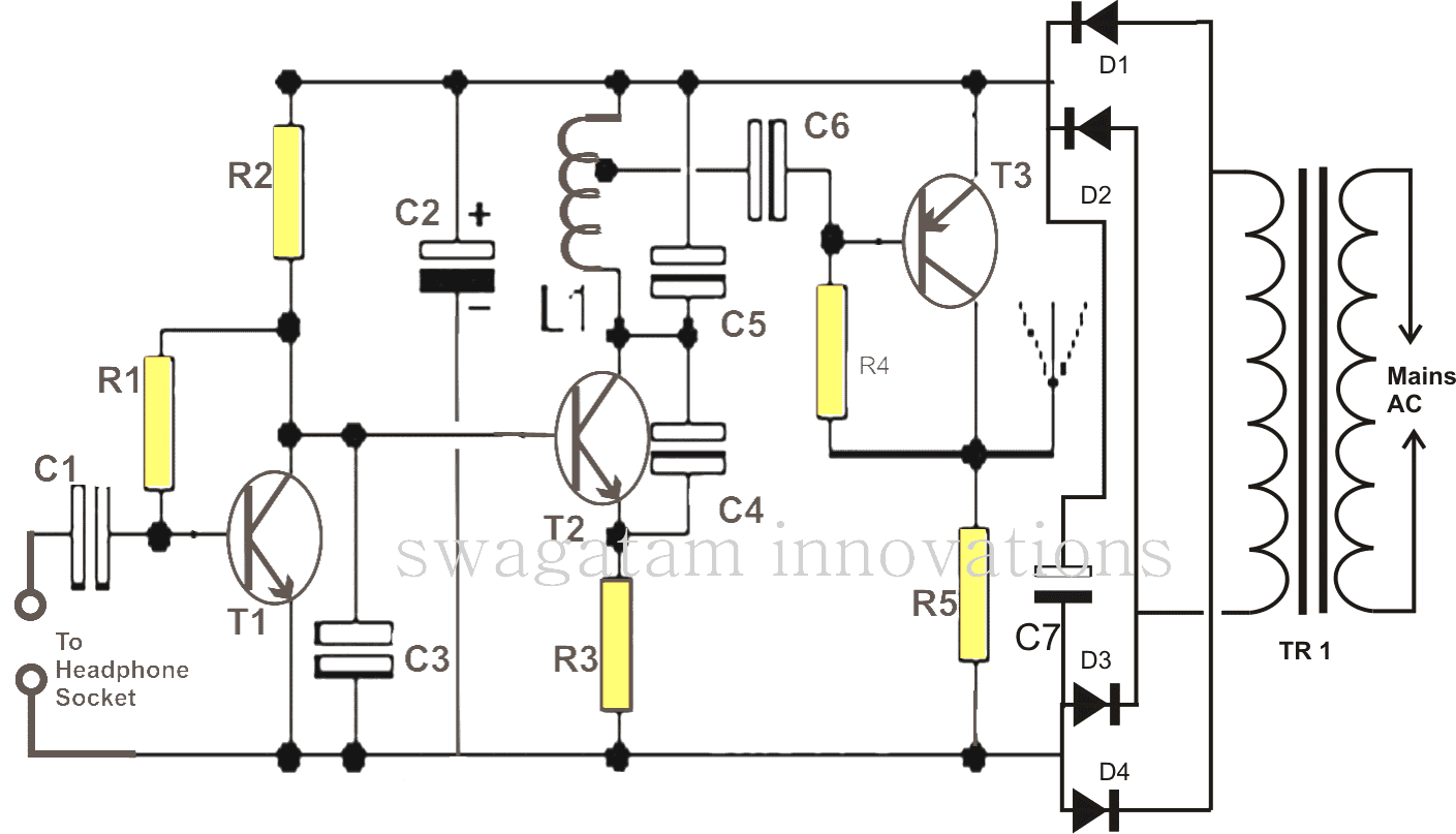
Transmitter Circuit:
As shown in the figure, the configuration looks a little different from the usual single transistor transmitter circuits where a single stage is used for the audio amplification and for the generation of the modulated carrier waves.
The usual single transistor transmitter circuit has the advantage of smaller and compact size and minimal power consumption, but is not suitable for long and strong signal transmissions.
However since such circuits are commonly used for wireless microphone applications, the distance is not a factor but compactness and low power consumption is definitely a must, and therefore becomes quite suitable for the intended application.
The present design is not intended for the above application so the first two features are not important, however the proposed idea of a wireless speaker system surely requires a long range and a distortion free power transmission, so that the reception can be heard at any corner of a particular premise or even across an apartment.
Therefore a stronger signaling or transmission of stronger carries RF signals becomes a necessity.
That’s exactly why we have incorporated a couple of extra stages in addition to the central carrier wave generator stage.
The first transistor and its associated components form a neat little audio amplifier stage and also a buffer between the audio source and the transmitter circuit.
This stage amplifies the received signal to stronger levels, and this stage also allows keeping the volume of the source signal to minimum levels.
The amplified signal is passed on to the next stage, which is the actual RF signal generator stage.
This stage is basically a simple feedback type of oscillator, wired to produce RF signals in the range of around 90 to 100 Mhz.
The amplified signal from the collector T1 start forces T2 to modulate the generated RF with the injected audio signals.
The modulated signal from the collector of T2 can also be directly used for the intended wireless music receiving.
However since we are interested in making it more powerful, we introduce another stage which becomes responsible for amplifying the modulated signals to much stronger levels so that it may be heard across many 10s of meters away and even in cell phone radios.
How to Make L1
The inductor L1 is the most critical part of the circuit. Its dimensions are: 1mm, super enameled copper wire, having 5 turns of 6mm diameter. The tap to C6 is taken by scratching the second last turn of the coil toward the positive side end.
The whole transmitter circuit can be built over a small piece of veroboard and housed inside a suitable sized metal box along with the required power supply section enclosed.
This concludes the transmitter circuit.
The Receiver Circuit
Ideally you won’t need to build this as the receptions can be heard crystal clear over an ordinary FM radio set. Therefore you might just want to use the FM radio itself as the wireless loudspeaker, or probably add an ampli-speaker box in conjunction to you FM receiver.
That’s it, your wireless speaker box system is ready and may be used for listening to any audio transmission without connecting wires across a radial distance of more than 50 meters, if the antenna is made large enough, the range may be well increased to beyond 90 meters.
Parts List
- R1 =1M,
- R2 = 2K2,
- R3 = 470 Ohms,
- R4 = 39K,
- R5 = 470 Ohms,
- C1 = 0.1 uF,
- C2 = 4.7 uF,
- C3, C6 = 0.001uF,
- C4 = 3.3pF,
- C5 = 10pF,
- C7 = 100uF/16V
- D1----D4 = 1N4007
- L1 = See Text
- T1, T2 = BC547B,
- T3 = BC557B
- TR1 = transformer, 0-9V, 100mA
Another Wireless Music Transmitter Circuit
The following diagram shows another miniaturized FM transmitter circuit that can be hooked up with a music source to send the music into the air in the wireless mode. A distant FM radio could be used as the wireless speaker is able to receive the signals and play the music.
The inductor L1 can be built by winding a piece of super enameled copper wire having a length of 6.5 inch, and thickness of 20 SWG over an air cored former having a diameter of around 1/4 of an inch.
Meaning, take a 6.5 inch long, 20 SWG super enameled copper wire and wind it over a 1/4 inch diameter air core former.
The music is fed from the input indicated as PL1

Questions & Answers
Was this built on breadboard or via soldering?
It was built by soldering.
Hi good day sir please i have few questions regarding this circuit,
1.i made the first circuit but the music isn’t clear i.e the noise is much more higher than the music.how can I solve this issue?
2.please can L1 be wound on a pencil because that’s what I used as the former.
3.i want to build the second circuit,where will the antenna be connected ?
4.can the transistors 2n3904 be replaced with bc547? Because I couldn’t find 2n3904 .
Hi Muhammad, please try testing with a 9V battery first, and not with an AC/DC adaptor, make sure the audio input is fed through a volume control and is adjusted properly. I have tested it myself, I did not find any distortions in it.
Pencil has a graphite core that may create problems, you can use it only for initial winding and remove the coil from it once it is wound.
In the second circuit, the antenna must be connected on the collector of Q2
yes BC547 transistors can be used in the second circuit
Hi Swag
when considering the capacitors C2 and C7 for the above circuit, please advise if C2 is necessary while C7 exists or I miss something important. Thanks
Hi Suat, both the the capacitors are required for improved flirtation of the AC ripples. In fact C7 must be rated as high as possible…
Hi Swagatam;
First thanks for sharing above circuit. Please advise if possible to make similiar circuit by using FS1000A 433MHz and XY-MK-5V radio communication dual circuits, or if it is possible to include them into above circuit instead of some parts like L1 and T3.Thank you so much.
Hi Suat, As far as I know, the 433MHz units are digital ICs, they cannot be used to transmit analogue audio. You may have to use Class-D amplifiers to make them work with audio signals.
Meaning, first audio will need to be converted to class-D PWM, then this PWM will need to be transmitted to the receiver, the receiver end then will need to be converted back to analogue audio using another class-D amplifier.
You are not provide any download link Arya PDF file
Try any online “webpage to pdf converter”….
I want the wireless speaker circuits, both transmitter and receiver
send me the cost and how to get the circuits.
I built a pond and waterfall and have it lighted for the nighttime but I cannot hear it. I would like to build a circuit that would pick up the sound and transmit it to a speaker wirelessly. Is that possible? Could I use two Arduinos for input and output and would it sound like anything beyond noise. Thanks.
If you want to pick the exact sound of water fall and send it wirelessly to another nearby location, the above circuit can do it without an Arduino.
Simply install the above circuit near the waterfall, and tune an FM radio receiver near you, to pickup the amplified the sound beside you.
Dear Swagatam,
Can I use 0.914 mm dia super enameled wire in place of 1mm dia?
Could you suggest me ant good websites to buy electronics components online?
Please reply as soon as possible.
Regards,
Santanu Dey
Hi Santanu, you can use 0.9mm wire, slight difference in the diameter will not affect the results. there are many online electronic part stores like digikey, mouser, onsemi, elemnt14 etc all are good.
Sir, Can i use a 9v DC power supply instead of the transformer, 4 diodes and the capacitor?
Jose, what kind of power supply are you referring to? is it an SMPS type? then it will do.
finally I found my mistake…. there was a connection problem at C3…..now there is no noise ….I got a really good sound…… I got success…… it is the result of your help and my curiosity….. this is my first circuit…. I never built any circuit before because I don't have a vast idea on circuit….. I am just a 12th pass student……you are the boss…. love you sir…
congrats Soumen!! that's indeed a great achievement, because RF circuits are never easy, especially for the newcomers.
I wish you all the best….and do keep posting your feedbacks.
sir my radio is catching regular FM stations mine…..but I don't know what is my frequency because my station is playing every where and I got some points where it became loud…….. in that points I can get a good sound hiz hiz sound……sir can u say me how to stop the nose…… thank you very much….
Soumen, take your radio to some distance, may be 10, 20 meters away from the transmitter, and tweak to locate the station which produces the most optimal and clean response.
you can also try your mobile FM for the same but from a closer distance to the transmitter
oh yes!!!! I tested it in a room it's working… sound is not clear…. I think inductor is the reason…..
OK, great, adjust the volume correctly and use a long antenna, high volume input or small antenna can affect the performance…
preferably use a 9V battery or if you are using a AC/DC power supply make sure to use a large filter capacitor across the supply terminals
you can try a mobile charger adapter as the power supply
I must make some mistake that's why it's not working…….. bye the way thanks for your valuable time sir…..
And sir can I use 2k7 in the place of 2k2…..thanks
yes will do
sir, I don't have 10pf I have two 4.7pf can I use ? if yes how??? thanks…. good night
connect them in parallel
Thank u fr this project I a got first prize finally.but not 100% good output I got…
I am doing again for tomorrow competition..
This time output is not coming..?time is too short.I want to show tomorrow..
Plese clarify some doubts sir
1)say capacitor code for (3.3pf&10pf) I can't get correct component from shop?
2)I am using 9 v battery.is c7 is necessory
3)can I use breadboard wire as inductor(after removing the plastic enamol)
4)say radious of winding &gap between winding
5)can u send image of coil using here.I want to see sir please my mail is ([email protected])?
6)please contact with me on mail great friend
Thank you for spending our time for me?
thanks sabari and congrats on your success.
3.3pF and 10pF does not require any code…you'll have to tell the shopkeeper as it's given
if you are using a battery then C7 might not be required…however a 9V PP3 batt will drain out quickly because the current consumption of this circuit can be pretty high.
the coil dimensions can be seen in the following example article,,,see the first image
https://www.homemade-circuits.com/2011/12/how-to-make-fm-remote-control-using-fm.html
you can see image here:
4.bp.blogspot.com/-UvYzmnSC_es/TusVkUH5pCI/AAAAAAAAAVI/MnHKf669lPw/s1600/Spy+Bug.jpg
the coil should be made from super enamel copper wires, other forms of wires will not do..
Hai great friend .I am sabari.I am dng it as a CLG science club competition.
Doubt is how the out put from eat wire should be connected on c1&ground help me sir.
Tomorrow I want to finish
Hi, you can apply any music input such as from the headphone socket of cellphone or TV, DVD player ipod or from any music gadget headphone socket
hello. sir could 50 meter range be extend to 100 or 150 meter? what could be done?
No it cannot be done without many elaborate modifications. You may refer to the following article for a possible solution.
https://www.homemade-circuits.com/2014/08/spy-bug-circuits.html
hello. can 50 meter range be extend to 100 or 150 meter?
can you provide us a wireless webacm circuit too so that we can connect this wireless speakers with a toy car and can make a wireless spy car ! can you recomend us how to add battery in the transmitter circuit instead of AC mains. can i use an anderoid mobile phone to hear the voice instead of the FM the mobile have the facility to adjust frequency too. Can we make the frequency more high so that we can use it for log distance ?
Thanz in advance.