The clap switch circuits explained here will toggle a connected load ON and OFF in response to alternate clap sounds? Here I have explained 4 unique and simple designs which can be selected as per user preference.
The article talks about what the title suggests – a clap switch. A small electronic circuit when built and integrated to any electrical appliance can be made to switch ON/OFF through mere hand clapping.
The proposed design when integrated to any of your electrical appliance can be used to switch it ON and OFF simply through alternate clapping of your hand.
The device becomes more interesting and useful because it does not require any external mechanism or device to carry out the specified operations.
How Sound Vibrations Trigger the Circuit
As you must have noticed the clapping of hands creates a loud sound and is sharp enough to move quite a distance.
The generated sound is in fact strong ripples or vibrations created due to the sudden compression of air in between our striking palms.

A mic is connected to the amplifier stage; the sound vibrations made by clapping hits the mic and get converted into tiny electrical pulses. These electrical pulses are amplified to suitable levels by the transistors or IC and are fed to the flip/flop.
The flip flop is a bistable relay circuit which switches ON/OFF the attached relay alternately in response to each clap sound.
The circuit presented here is basically made up of two stages, the first stage is a two transistor hi-gain amplifier and the second stage consists of an efficient flip/flop.
The flip/flop stage alternately switches the output relay driver in response to every subsequent clapping. The load connected to the relay thus also gets activated and deactivated correspondingly.
The circuit may be further understood with the following explanation.
1) Clap Switch Circuit Using IC 741.
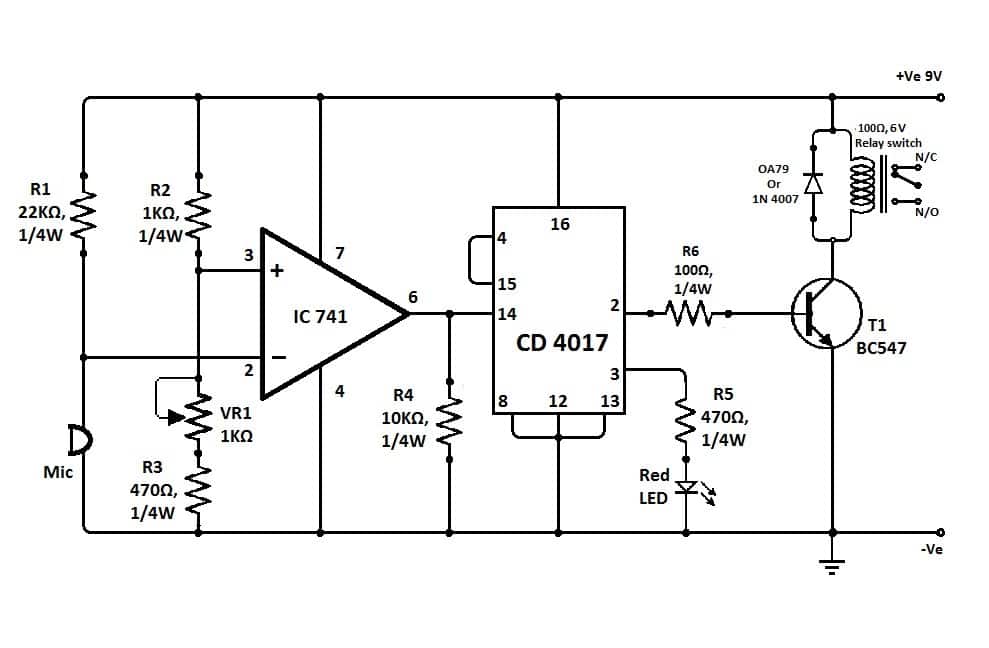
The above clap operated relay circuit was provided to me by one of the keen readers of this blog Mr. Dathan.
The circuit is very easy to understand:
The opamp here is configured as a comparator, meaning it is positioned to differentiate the slightest of voltage differences across its two inputs.
When the clap sound hits the mic, a momentary drop of voltage is experienced at pin#2 of the IC, this situation raises the voltage at pin#3 of the IC for that instant.
As we know, with pin#3 at higher potential than pin#2 makes the output of the IC high, the condition puts the output of the IC go high momentarily.
This high response triggers the IC 4017 pin#14, and forces its output to either move from pin#2 to pin#3 or vice versa depending upon the initial situation of the outputs.
The above action switches the load accordingly either to ON or OFF position.
The above 12 V clap triggered switch circuit using IC 741 was successfully tried and tested by Mr. Ajay Dussa. The following prototype images for the same were sent by Mr. Ajay.
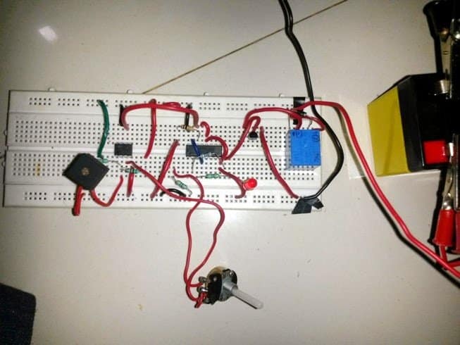
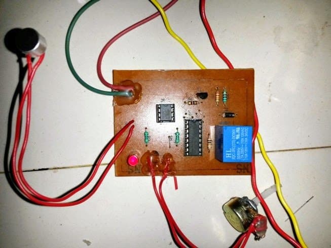
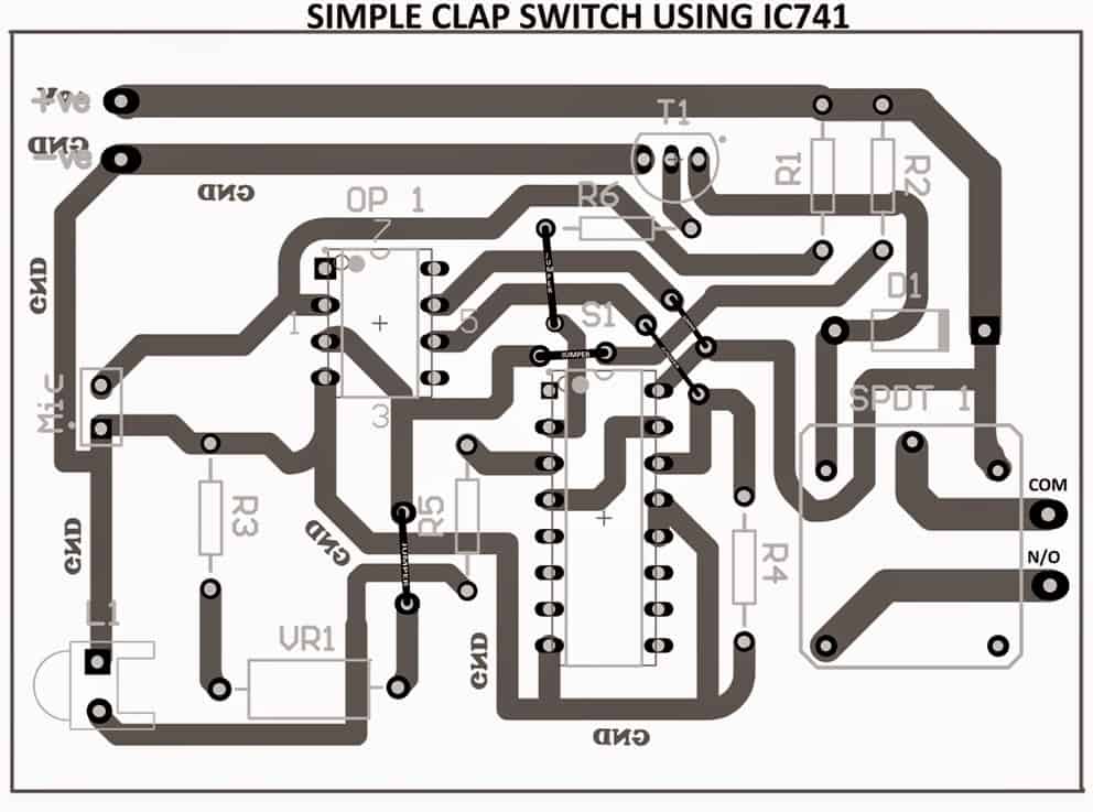
The PCB design (track layout) for the above can be seen below, as designed by Mr. Ajay:
Parts List
| Category | Part | Specification | Notes |
|---|---|---|---|
| Semiconductors | IC1 | 741 operational amplifier | |
| IC2 | CD4017 decade counter IC | ||
| T1 | BC547 NPN transistor | ||
| D1 | OA79 or 1N4007 diode | Flyback diode for relay protection | |
| Capacitors | - | No capacitors in the schematic | |
| Resistors | R1 | 22kΩ, ¼W | |
| R2 | 1kΩ, ¼W | ||
| R3 | 470Ω, ¼W | ||
| R4 | 10kΩ, ¼W | ||
| R5 | 470Ω, ¼W | Connected to LED | |
| R6 | 1kΩ, ¼W | Base resistor for T1 | |
| Potentiometer | VR1 | 1kΩ variable resistor (trimmer) | Used for sensitivity adjustment |
| LED | - | Red LED | Indicator output |
| Microphone | MIC | Electret microphone | Sound detection input |
| Relay | K1 | 6V, 100Ω SPST relay switch | Used for switching external load |
| Power Supply | B1 | 9V battery | Circuit power source |
2) Clap Switch Using Transistors or BJTs
In the above explanations I have explained a simple clap activated switch circuit which incorporated an IC for implementing the desired ON/OFF toggling actions. The present design uses a different principle and utilizes only transistors for the above triggering actions.
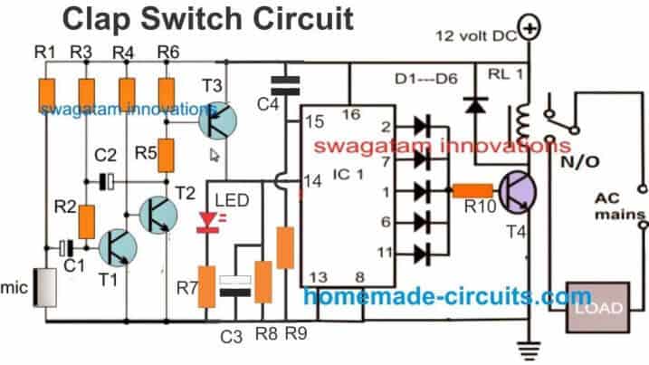
Clap Switch Video Demonstration
Parts List
- R1 = 5k6
- R2 = 47k
- R3 = 3M3
- R4 = 33K
- R5 = 330 OHMS
- R6 = 2K2
- R7 = 10K
- R8 = 1K
- R9, R10 = 10K
- C1, C4 = 0.22uF
- C2 = 1uF/25V
- C3 = 10uF/25V
- T1, T2, T4 = BC547
- T3 = BC557
- All IC diodes = 1N4148
- Relay diode = 1N4007
- IC = 4017
- Relay = 12v / 400 ohms
How it Works
The figure above shows a straight forward two stage sound activated switch.
The first stage comprising T1, T2, and T3 forms a hi-gain common emitter amplifier configuration.
A mic is connected at the base of T1 via blocking capacitor C1.
Strong sound vibration hitting the mic is instantly picked and converted into tiny electrical pulses.
These are in fact small AC pulses easily make there way through C1 into the base of T1.
This creates a kind of push-pull effect and T1 also conducts in the corresponding way.
However the response of T1 is relatively weak and requires further amplification.
Transistors T2/T3 are introduced exactly for this and help to improve the voltage peaks created by T1 to appreciable levels (almost equal to the supply voltage.)
The above voltage pulse is now ready to be use for toggling the relay ON/OFF and is fed to the relevant stage.
IC 4017 as we all know produces sequential shifting of its output pin-outs (logic high) in response to every positive pulse at its clock input pin 14.
The amplified clap sound voltage pulse is applied to pin 14 of the above IC, this flips the output of the IC to either a logic high or a logic low depending upon the initial status of the relevant pin-out.
This triggered output is appropriately collected at the diode junctions and used to toggle a relay through a relay driver transistor T4.
The relay contacts ultimately goes to a load or an appliance which is correspondingly switched ON and OFF with every subsequent claps.
Using BJTs and Power Supply
Looking at the circuit diagram we see that the entire circuit has been configured around ordinary general purpose transistors.
The functioning of the circuit may be understood with the following points:
Transformer X1 along with the D1 and the capacitor C4 forms the basic power supply circuit for providing the required power to the circuit.
The first stage which includes R1, C1, R2, R3, R4 and Q1 form the input sensor circuit.
The next corresponding stages consisting of Q2 and C3 form the flip flop stage and makes sure that the signals from the input sensor stage is appropriately converted into alternate toggling of the output.
The output stage consists of a single transistor Q4. It is basically configured as a relay driver stage for translating the alternate ON/OFF actions from the previous stage into physical toggling of the connected load across the relay terminals.
The design is very old, I built it in my school days by assembling a kit. The circuit diagram using transistors is shown in below:
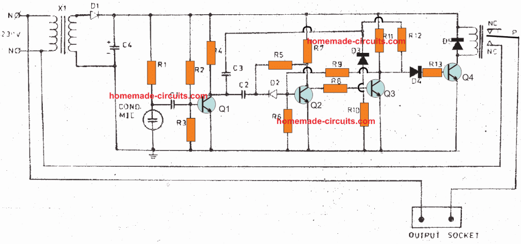
Parts List
- R1 - 15K
- R2,R5,R12- 2m2
- R10, R3 -270K
- R4 - 3K3
- R6 - 27K
- R7,R11 - IK5
- R8,R9 - 10K
- R13 - 2K2
- C3, C1 - 10KPF Disc
- C2,3 - 47KPF Disc.:
- C4 - 1000uF/16V;
- Q1,2,3,4 - BC547B
- D1 - 1N4007
- D2,3,4,5 -1N4148 _
- Xl - 12V/300mA Transformer .
- MIC - Condenscr Mic
- RLY — 12V Single Charge over relay
Another version of the above can be seen in the following diagram:
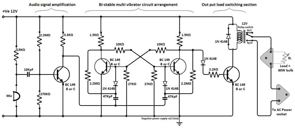
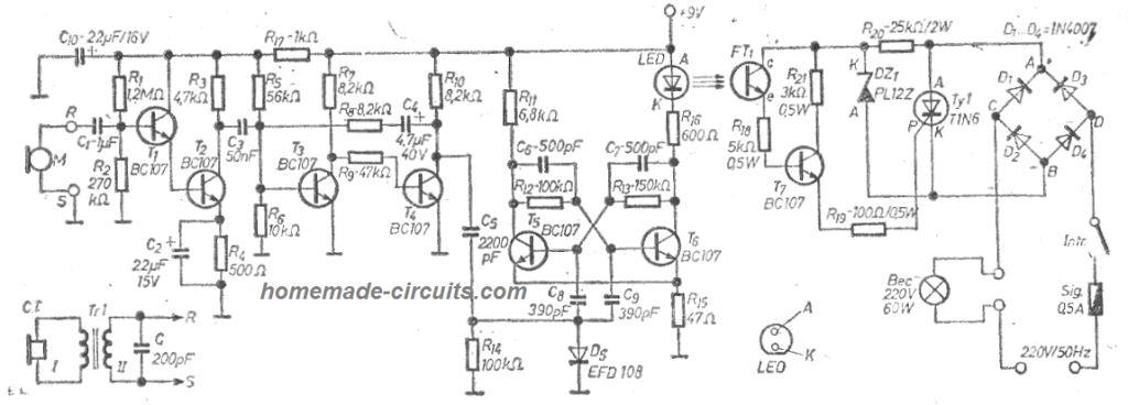
3) Double Clap-Clap Switch Circuit
All the clap-on switch circuits explained above have the ability to operate only with single alternate clap sounds.
This feature makes the circuit vulnerable to external sounds which might occur occasionally triggering the connected load with the circuit.
A double clap operated circuit thus becomes more suitable and resistant to spurious triggering due to the fact that it would toggle only in response to two subsequent clap sounds instead of one.
The explained circuit is simple yet effective and does not employ microntrollers for the implementation unlike other circuits on the net.
The circuit has been tested by me, but it is a fairly complex design it's important to first understand the stages convincingly, and then build it to avoid failures.
Circuit Operation
The proposed clap-clap circuit or double clap circuit functioning may be understood with the following points:
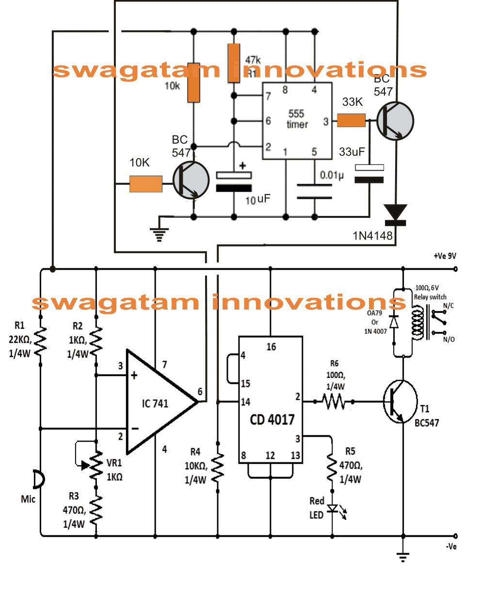
The lower stage is basically a simple sound activated switch circuit which would activate with any loud sound.
The IC 741 is rigged like a comparator with its pin#2 referenced at some optimal fixed potential determined by the setting of the given preset VR1.
Pin#3 of the IC becomes the sensing input of the IC and is connected with a sensitive mic.
The adjoining IC 4017 is a bistable stage which activates the connected relay driver stage and the load alternately in response to every positive high pulse at its pin#14.
When a loud sound such as a "clap" hits the mic, it momentarily grounds pin#2 of the IC741 resulting in a momentary high pulse at its pin#6.
If we connected this output to pin#14 of IC4017 would have resulted in an instant toggling of the load with every single sound input which we don't want here to happen, therefore the response at pin#6 of IC741 is broken and diverted to an IC 555 monostable stage.
How IC 555 is Configured
The IC 555 circuit is rigged in such a way that when its pin#2 is grounded, its output pin#3 becomes momentarily high for some period of time depending upon the values of the 10uF capacitor.
When a sound hits the mic, the high pulse from IC741 output triggers the BC547 attached to pin2 of IC555 which momentarily grounds pin#2 of IC555, which in turn put its pin#3 high.
However the instantaneous high at pin#3 of IC555 takes a while to reach the connected BC547 due to the presence of the 33uF capacitor.
By the time the 33uF charges and switches ON the transistor, the potential at the collector of the transistor is already gone due the absence of the clap sound which happens only momentarily.
However with the application of the immediate subsequent clap provides the required potential at the collector of the transistor which is now allowed to the reach pin#14 of the IC 4017.
Once this happens the relay driver triggers or deactivates depending upon its initial condition.
The toggling of the load thus takes place only in response to a pair of clap of sounds making the circuit reasonably foolpoof.
Another Double Clap Switch Circuit
High pitched sound generated by clap of hands, click of fingers and a various other methods can be used to trigger the next circuit.
The design necessitates a minimum of two intense clap sound pulses to initiate the triggering.
This significantly minimizes the chance of unwanted haphazard switching of the device, due to spurious accidental sound.
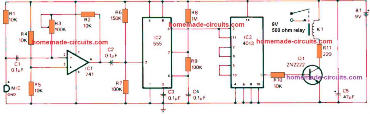
The first sharp hand clap is detected by the electret microphone and is fed into operational amplifier ICI's inverting ( -) input at pin 2 via C1.
The signal negative peak at the pin 6 output of IC1 subsequently activates 555 timer IC2, that is set up like a monostable multivibrator.
The trigger signal reaching the pin 2 input of IC2 is internally extended to toggle the dual D flip-flop IC3. With the help of the three-state counter configuration of IC3.
Not one but two sharp clap sounds are necessary to create a positive output at pin 1 that causes Q1 into switch ON. When Q1 activates the relay and switches its contacts to N/O points.
Any electrical appliance attached to the relay's contacts now switches on.
As soon as pin 1 of IC3 becomes high, it continues to be in that situation until a subsequent two powerful hand claps hit the MIC to repeat and revert the condition.
Thus, it requires two loud sound inputs to switch off the electrical load hooked up to the relay's contacts after the circuit is activated.
PCB Design and Component Overlay
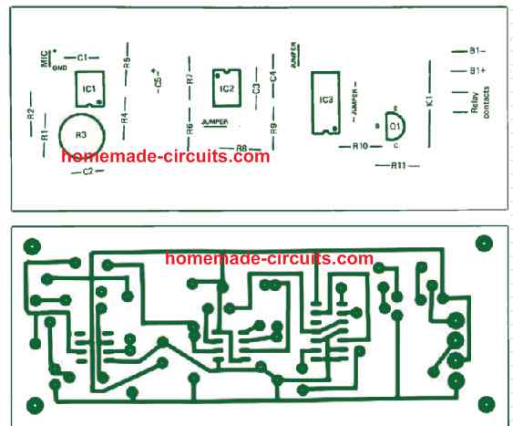
Part List
| Category | Part | Specification | Notes |
|---|---|---|---|
| Semiconductors | IC1 | 741 operational amplifier | |
| IC2 | 555 timer | ||
| IC3 | 4013 dual D flip-flop | ||
| Q1 | 2N2222 or similar general-purpose NPN transistor | ||
| Capacitors | C1, C2, C3, C4 | 0.1 µF ceramic disc | 15V or more |
| C5 | 47 µF electrolytic | 15V or more | |
| Resistors | R1, R2, R4, R5, R10 | 10,000 ohms (10kΩ) | ¼ watt, 5% tolerance |
| R6 | 150,000 ohms (150kΩ) | ¼ watt, 5% tolerance | |
| R7, R9 | 100,000 ohms (100kΩ) | ¼ watt, 5% tolerance | |
| R8 | 1 megohm (1MΩ) | ¼ watt, 5% tolerance | |
| R11 | 220 ohms (220Ω) | ¼ watt, 5% tolerance | |
| R3 | 100,000-ohm (100kΩ) PC-type trimmer potentiometer | ||
| Miscellaneous | B1 | 9-volt transistor battery | |
| K1 | SPST reed relay with 5V DC coil (Radio Shack Cat. No. 275-232 or similar) | ||
| MIC | Electret microphone element |
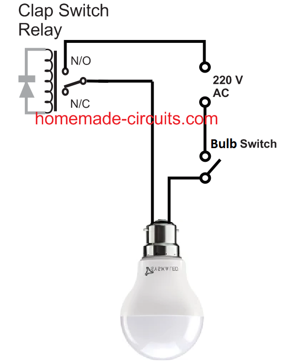
How to Connect 220V Load to Clap Switch Relay
The main application of the clap switch circuits described below is for controlling home appliances like light bulbs and fans.
Suppose you want to connect a ceiling fan with this circuit so that you can switch it ON or OFF with alternate clap sound, you can easily do it, by wiring the fan 220 V AC input through the relay of the circuit.
Similarly, if you wish to switch a tube light or any 220 V or 120 V AC lamp, just wire it in series with the relay of the clap switch.
The following image shows how to connect fan with the relay
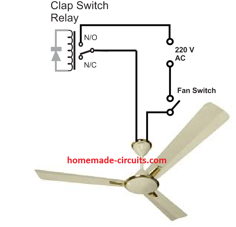
The fan regulator can be connected anywhere in series with the wiring.
Any light bulb can be connected with the clap switch relay as given in the folowing figure


Questions & Answers
Dear Swagatam,
Can You help me with RF receiver transmitter circuit which is compatible HT640 and HT648L. And I don't want the readymade circuit which is available, I want to make my own so please provide circuit if possible.
sir i am new one to this…will it work sir ?
did u check it sir ?
Dear Swagatam I am in need of RF receiver transmitter circuit compatible with HT640 and HT648L. I want to make the circuit on my own so dont want the readymade available in market
Dear kkaranjia,
you may refer to the following article, the basic principle will be the same as explained here, just the pinout configuration will be different for your ICs:
https://www.homemade-circuits.com/2013/07/simple-100-meter-rf-module-remote.html
Dear Swagatam
I already know about this readymade RX-433 and TX-433 but i want to make circuits on my own so don't want to use this readymade ones. can we use the receiver transmitter circuit that is used with TX-2b and RX-2b???
Dear kkaranjia,
Yes, it can be used but what will you insert in the RF stages.
I didnt get your point. I want to make circuit 8 chanel transmission so i am using ht640 and ht648l for this purpose. its just for remotely controlling 4 motors. i am planing to use two L293d at the output bits of ht648l
I responded to your previous comment where you mentioned TX2b and Rx2b chips. These chips require RF stages for operating an RC model
Dear Swagatam you asked that what will i insert in RF stage so didnt get this question of yours and i have circuit regarding this rf stage can u help me evaluate it, if yes then i can sent you the images on your email id.
Dear kkaranjia,
I was referring to the following circuits:
datasheet.eeworld.com.cn/pdf/SILAN/153017_RX-2B.pdf
anyway you can send it to my email ID.
Dear Swagatam
I know of this circuit and i want to the rf portion form this circuits and incorporate it with HT640 and HT648l so can i do that and if possible then what changes have to be made in the circuit???
Dear kkaranjia,
If you are intending to use the circuit which is given in the above mentioned datasheet then you will have to incorporate the RF modules shown in the first image of this article. HT640/648 cannot be used as they are en/decoders, not RF chips.
https://www.homemade-circuits.com/2013/07/simple-100-meter-rf-module-remote.html
Dear Swagatam i will be sending you a circuit diagram in mail. kindly verify and tell weather it can work properly or not??
OK, you can send it
hi my name is jaco.
i have a electronic project where im required to build a clap switch using the following componets:
33 k ohm 1/4 W 5%
1 M ohm 1/4 W 5%
5 K 6 ohm 1/4 W 5%
270 ohm 1/4 W 5%
47 k ohm 1/4 W 5%
BC 547
100 uF 16 volt redail
10 uF 16 volt redail
1 uF 16 volt redail
1N4148 diode
5mm LED (red or green)
electret microphone
6 V DC PSU
could yo please explain how to connect the circuit. this is my first time.
thanks.
Jaco
Jaco,
you can refer to the following circuits, it closely matches your application:
https://www.homemade-circuits.com/2012/04/simple-clap-switch-circuit-using-only.html
In the above article "Make a Simple Electronic Clap Switch Circuit", only one 230V supply line will pass through the circuit, right? And the other will directly go to the load?
If yes, where do I exactly connect the two wires in the circuit, the first one coming from the supply line and the second one going to the load ( I can't understand that from the diagram)
As I am an amateur, any help will be greatly appreciated.
It's correct, one of the AC mains line will go to pole of the relay, while one of the load wires will go to the N/O contacts of the relay, you may refer to the following article for knowing more about relays:
https://www.homemade-circuits.com/2012/01/how-to-understand-and-use-relay-in.html
Thanks! and I have one more doubt- according to the diagram given at the end of the article on this page- https://www.homemade-circuits.com/2012/01/how-to-understand-and-use-relay-in.html
I have to connect the coil terminals in the DC circuit (which we are making), and one of the AC mains to the middle pin i.e. movable contact and the load line to the N/O terminal, right?
Yes that's correct.
You can try the second circuit, it has more chances of succeeding, although both are untested.
Sir! I wonder one point sir..does this circuit active only with clap sound? And about other sound like speech sound? What happen when there are alot sound in that place?
any loud sound will activate this device….it's more of a toy than a genuine switching device.
I try to replace with 1uf to 10uf, but it is still the same.
Hi, I am doing this for a project in my electronics class at school I have breadboarded the circuit exactly as above but nothing happens when I clap. I replaced the microphone with a switch to test also but that didn't work either. Can you please help me find the problem?
which circuit did you make? Try the second one, it will surely work according to me.
Sorry, the first one worked fine it was my fault I was using a polarised capacitor for C2 :S
OK, thanks!
Sir.! I want to make a circuit about voice interrupt music..this circuit consists of two input, audio input and mic, and one output to amplifier. First, the input from any audio player. While playing, if their is any sound into microphone, audio will become mute. After the sound from microphone is stop, the audio will be increasing its volume rapidly to its initial volume for some seconds. So, can you guide me some sir?
Hi Seok,
I'll try to design it soon and inform you , also let me know where and how you are going to use this circuit?
what is the output of the relay in the second circuit?
via N/O
below circuit published by u does not work when i clap nothing happens i have checked my all connections twice only the red LED glows
do we have to use the same parts for the second one?
Please, I have no access to IC741. Can I connect the amplification stage of diagram 1 to the 4017 flip flop configuration of diagram 2……. Merry xmas
yes you can do it.
I have assembled the board for an extra credit project for an engineering physics class however it is not working. When I connect power to the circuit I'm getting a random array of lights either one or two and clapping has no effect on the system, any ideas what could have caused this? I have checked and rechecked and the diagram has a few mislabeled items such as two R5's and no R3. Please help me thank you very much.
The circuit could need some fine tuning and tweaking before it produces the intended results.
You can try the following few thing's:
decrease R1 to 2.2k or to any smaller value
remove C3 from its shown position and place it in parallel to the collector resistor of the BC557,
use BC547 for T1.
I'll correct the mislabeled pats quickly…
By the way there are no lights in the circuit??
dear sir,
i m a student. my teacher has gave me this model
will u please give a easy stepwise note that how can i make this………
plzzzz sir……
hello sir i want 2 make a clap switch for my requirement but how can i use it for a dc supply.what changes to be made for the above circuit to use it in dc supply. i will thank full to u if u suggest me
hello Harish, what is the DC load that you intend to connect?
its 9-12volts sir
Harish, you can use a standard 12V, or 9V AC/DC adapter for powering the circuit, even a mobile charger will work if a 5V relay is used, no changes would be required.
i dnt knw hw to connect the relay in the circuit can u pls help me
pick up the pot from ckt
hello sir,
I make second circuit as shown by the circuit diagram, only Red LED glow. I didn't understand the reason.
Is there any specification of mic.
Plz help me im very thankful to u
Hello Mahesh,
connect another led in series with R4, now adjust the preset carefully until it just shuts off…now clap in front of the MIC, the circuit should respond as proposed, and this LEd will momentarily flash and again shut off.
will it work for high loads like 60(or)80watts bulb
yes it will…
What's the exact name of the IC714? I can't find it in any store in mu country by the name 714 or IC714.
It's IC 741 not 714
Just ask for "IC 741" or "opamp IC 741"
thanks
Does the mic have polarity? And the relay is 12V ?
yes MIC has a polarity, check its pins, the one which is isolated from the body ground track is the positive and will go to the IC input pin2, relay voltage must be equal to the supply voltage
What is the 1K POT used for?
for adjusting the sensitivity
Could you post the pcb layout in the real size?
provide the shown PCB design to the PCB maker, he'll do the rest.
I have made the circuit but my led's just blink when i clap. Could that be the foult of the CD4017 chip?
yes it could be, before concluding do a modification, connect a 10uF capacitor parallel with R4 and check again.
I don't have a 10uF capacitor and the stores are all closed for the next few days, will a 22uF work?
22uF will also work, you can use it.
Iave placed the capacitor and it it's working better but not like it's suposed to. Sometimes it just starts to blink and it doesen't stop and when i place the relay it just turns off. I have relapced the cd4017 chip with another and insead of a pot i used a 1kohm resistor which i now replaced with a 470ohm resistor and now it's just worse.
the pot is required so that the sensitivity and optimal working from the IC741 can be adjusted and ensured, if you remove it you would be unable to do the above settings
the 4017 seems to be not functioning correctly…you may need to check it separately.
break the link between pin6 of 741 IC and pin14 of 4017 but do not remove R4 and the parallel capacitor from pin14.
Now manually touch pin14 to positive with a piece of wire, the relay should respond with an alternate ON/OFF sequence..this would confirm a good 4017 otherwise some other fault could be suspected.
nope it doesen't work. i mean the relay doesent turn on. However i measure the voltage between the colector and the postivie voltage supply and it;s about 3V volt's.
it means your IC 4017 is not responding, may be it's faulty, put diodes at the output of the 4017 as shown in the first diagram and do the connections accordingly for the relay and the transistor also…..try it before discarding the IC.
you mean i should make the first schematic?
no, not the whole circuit, replicate only the diode section which are connected to pins 2,7,1,6,11 of the IC4017, make sure that now pin15 is connected to ground.
Just finised that but now not even the rel led doesen't turn on
connect one LED in series with R4 also and check its response, if this LEd lights up very brightly will ensure a proper functioning of the 741 section….then you can only replace the 4017 IC and recheck.
hello Mr. Swagatam Majumdar……
plzz sort out my problem as soon as possible…..
i made mr.ajay's circuit …it works perfectly but the main problem is the sensitivity of the mic….plzz tell how can i increase the range of mic to the extreme level…. i need the mic to work at least at the range of 5m….if its not possible…what is the maximum range of the mic….waht modifications should i do in the circuit…. plzz reply
Hello Mr.Swagatam ……I have a minor problem…i made mr.ajay's circuit….but the problem is the sensitivity of the mic….the sensitivity of the mic is very low…it doesn't even responds from 0.5 feet…plzz tell how could i increase the range of mic to the extreme level….. i will be thankful for your quick reply…
hello harishwar, try a 10k preset in place of the shown 1K, and adjust it carefully to achieve the required sensitivity….hopefully this should solve the issue, other wise we may have to seek other options.
Hey, iam from indonesian, i want to ask question, look over the PCB according to the first pat sensor circuit or the second ? ( clap simple switch that was given to me by one of the readers of this blog Mr. Dathan sharp . )
the PCB design is for the second circuit…
Hello, I would like to use this circuit as a school project (toy car) using a 9v battery. How do I exactly do that and also, I already bought all the parts and a 9V motor and a 9V battery
Hi, you can try the IC 741 circuit, however it'll need to be tweaked appropriately for getting the most optimal results
Sir, could you please tell me how to design a clap switch which turns on for 2 claps and turns off for one clap?
Anirudh, I have the circuit posted in the following article:
https://www.homemade-circuits.com/2013/04/clap-clap-switch-circuit-double-clap.html
but it will switch off also with two claps
Thanks a lot for your time and help sir.
If it's not a problem could you please tell me how to turn it off for a single clap?
Thank you again sir.
Anirudhs, the linked circuit is designed to work with two claps (ON/OFF), to make it operate with a single clap switch-OFF will require a complete change in the configuration and will make the design much complex….so it is not advisable to do so, moreover a single clap will make the design vulnerable to ambient noise.
why the collector in transistor is in the ground in the pcb layout?
It is a "component side view" layout
Dear sir,
I tried out the clap switch which turns on for two claps as suggested by you. But it is not working. Could you please tell me what's the problem?
Dear Anirudh, I'll try to update the article with a new easier one soon, you can try that once it's posted
I did and did not work the first circuit.
Can you give me an idea of what is not.
you can try the second opamp circuit or the one which is shown in the following article:
https://www.homemade-circuits.com/2012/04/simple-clap-switch-circuit-using-only.html
Hi swagatam ,I made a clap switch it's different from what you have posted here but works the same way. I want to Decrease it's sensitivity to make it a bit practical.
I was wondering if I could add a pot in series with the mic,will it help ?
Hi Shirish, yes you can put a pot or a preset in series with "R1" and adjust it appropriately for the required level of sensitivity.
hey what different thing can we use instead of led??
and use of relay is complusory??
LED is used for indicating the clap response, it cannot e replaced by anyuthing else.
the relay is for switching a load ON/OFF in response to the claps…
Sir in second diagram where to connect VR1 as it contains 3 pins (the printed side facing us right side pin is negative, center pin is out, and right side is positive.) as per your diagram two pins are connected. Please help regarding this thank you.
Manjunath, VR1 here should be a preset not a pot, and by the way presets and pots do not have polarity, so the orientation is not critical.
you can use the center pin and any one of the outer pins, and leave the other pin free (unused)
SIR I MADE THE SECOND CIRCUIT BUT SEEMS IT WAS NOT SENSING ACCURETLY. AS YOU SAID IT WAS NOT SENSING ABOUT 10 FEET DISTENCE .I SHOULD TOO NEAR TO THE MIC ,THAT ALSO NOT SENSING PROPERLY.
WAS THE FIRST CIRCUIT WAS MORE ACCURATE THAN THE SECOND PLEASE HELP ME
THANKS
Manjunath, you will need to adjust the 1K preset precisely for getting a proper response from the cirucit.
Initially, make sure the output of the IC just merely turns "low" (0V), by adjusting the 1K preset.
Thia will set-up the circuit optimally and claps from a little distance will also become responsive
this circuit is better than the first one.
sir any minor changes can made to second circuit that lead to more sensitive and responce small sound genarated by clap. now I was still struggling to adjust 1k preset as you said above. thanks
you can try connecting a small value capacitor across pin6 ans pin3….this should improve the sensitivity of the circuit manyfolds
still the 1K perset adjustment will be crucial.
sir small value capacitor means which capacitor can i use and does it has polarity
preferably it should be non-polar…you can try a 0.22uF, or a 0.33uF etc
sir i bought 0.22uf capacitor but it has polarity then which side to connect #pin 3 and #pin 6 ( #pin 3 positive and #pin 6 negetive . may i correct)
and was this 0.22uf capacitor to connect IC 741
thanks