• Skip to main content
  • Skip to primary sidebar

Homemade Circuit Projects

Need circuit help? Post them in the comments! I've answered over 50,000!

Blog | Categories | About | Hire Me | Contact | Calculators-online
You are here: Home / Energy from Magnets and Earth / Make a Football Electricity Generator Circuit

Make a Football Electricity Generator Circuit

Last Updated on May 21, 2026 by Swagatam 5 Comments

The explained football electricity generator circuit was developed by me in response to the request sent by one of the readers Mr.Bright.

Table of Contents
  • Designing the Generator
    • How the Coils and Magnets are Assembled inside the Ball
      • What Happens when the Football is Kicked

Though I am not sure if the explained concept would actually give the intended results, it's worth trying as it's quite easy to understand and build.

Designing the Generator

There were three things that I had to consider while designing the circuit, firstly the circuit should be easy and cheap to build, second, should be reasonably efficient and thirdly it should be well aligned such that it does not disturb the ball dynamics while playing.

We are all familiar with Faraday's law of electromagnetism which says that when a when a conductor is subjected to a varying magnetic field, a flow of current is initiated in te conductor.

The above principle has been exploited here for generating electricity inside a football where the process starts when the ball is kicked or while the ball is rolling on the ground.

How the Coils and Magnets are Assembled inside the Ball

As shown in the figure, a magnet and a copper wire coil arrangement has been neatly assembled inside a polished plastic tube.
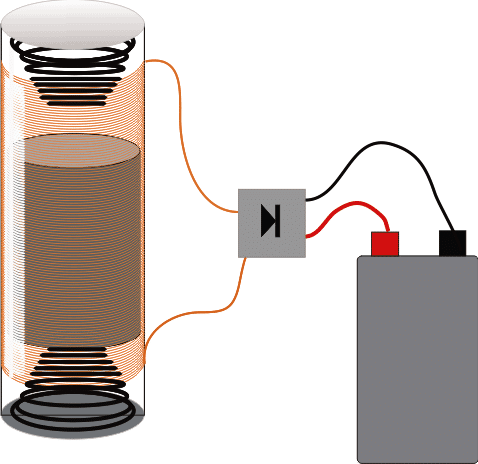
The tube encloses a cylindrical magnet having a north (N) and south (S) pole over its ends. The magnet diameter and the internal tube diameter are chosen such that the magnet just slides inside the tube freely without wobbling sideways much.

The tube top and bottom portions are sealed with lids having a low tension spring fixed inward for facilitating a bouncy effect to the jumping magnet.

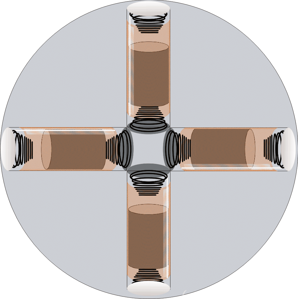
Four such assemblies are positioned perpendicular to each other inside the football for keeping a uniform alignment to the ball and its dynamics.

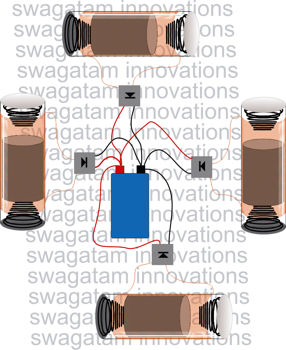
The coil wire terminals from each assembly is connected to individual bridge rectifiers and the outputs from all the bridge rectifiers are appropriately connected to a correctly rated battery, either a Li-Ion or Ni-Cd.

The whole assembly along with the battery is then neatly framed and securely fixed inside a football.
What Happens when the Football is Kicked

Now if the ball is kicked, a strong vibrational motion is delivered to all the magnets inside the tubes which start oscillating to and fro, giving rise to the Faraday's effect, inducing electricity across all the coils.

The above process would continue even while the ball roles over the ground.

The generated voltage across all theses coils is finally applied to the battery which hopefully starst getting charged as per the expectations.

The battery output is terminated out from the ball through some sort of plug-in arrangement made over the ball itself which cleanly merges with the ball diametric curve without distorting it's shape.

A small LED lamp would then light up using the charge from the football battery, once it gets charged after a good play session.

You'll also like:

  • piezoCharging Battery with Piezo Mat Circuit
  • 8X Overunity from Joule Thief – Proven Design
  • levitation set up compressedElectromagnetic Levitation Circuit [Anti-gravity]
  • free2Benergy2Bfrom2BpendulumHow to Generate Electricity from a Pendulum

Filed Under: Energy from Magnets and Earth, Games and Sports Projects Tagged With: Electricity, Football, Generator

About Swagatam

I am an electronics engineer and doing practical hands-on work from more than 15 years now. Building real circuits, testing them and also making PCB layouts by myself. I really love doing all these things like inventing something new, designing electronics and also helping other people like hobby guys who want to make their own cool circuits at home.

And that is the main reason why I started this website homemade-circuits.com, to share different types of circuit ideas..

If you are having any kind of doubt or question related to circuits then just write down your question in the comment box below, I am like always checking, so I guarantee I will reply you for sure!


Previous Post: « 5 Best 6V 4Ah Automatic Battery Charger Circuits Using Relay and MOSFET
Next Post: Battery Charger Problems Troubleshooting Discussed »

Reader Interactions

Questions & Answers

Total Posts: 5
Newest Oldest
Unknown
April 8, 2017 • 9 years ago #49669

Do anybody got the result?

Reply
Unknown
April 8, 2017 • 9 years ago #49670

Do anybody got the result?

Reply
Vibin Vijay
April 8, 2017 • 9 years ago #49671

Sir, what is the length of the magnet used?

Reply
Vibin Vijay
April 8, 2017 • 9 years ago #49672

Can I go ahead with this project for my exam?

Reply
SwagatamAdmin
April 8, 2017 • 9 years ago #49675

Vibin, you can go ahead with this project there's nothing critical about the design, you can first build the following and then implement it in the ball

https://www.homemade-circuits.com/2016/11/shake-powered-flashlight-circuit.html

Reply

Need Help? Please Leave a Comment! We value your input—Kindly keep it relevant to the above topic! Cancel reply

Your email address will not be published. Required fields are marked *

Primary Sidebar


Categories

  • Arduino Projects (95)
  • Audio and Amplifier Projects (134)
  • Automation Projects (18)
  • Automobile Electronics (103)
  • Battery Charger Circuits (89)
  • Datasheets and Components (109)
  • Electronics Theory (150)
  • Energy from Magnets and Earth (40)
  • Games and Sports Projects (11)
  • Grid and 3-Phase (20)
  • Health related Projects (27)
  • Home Electrical Circuits (13)
  • Indicator Circuits (16)
  • Inverter Circuits (100)
  • Lamps and Lights (163)
  • Meters and Testers (72)
  • Mini Projects (28)
  • Motor Controller (68)
  • Oscillator Circuits (30)
  • Pets and Pests (15)
  • Power Supply Circuits (91)
  • Remote Control Circuits (50)
  • Security and Alarm (65)
  • Sensors and Detectors (107)
  • SMPS and Converters (46)
  • Solar Controller Circuits (62)
  • Temperature Controllers (44)
  • Timer and Delay Relay (50)
  • Voltage Control and Protection (44)
  • Water Controller (37)
  • Wireless Circuits (31)


Circuit Simulator

circuit simulator image


Subscribe to get New Circuits in your Email


Other Links

  • Privacy Policy
  • Cookie Policy
  • Disclaimer
  • Copyright
  • Videos
  • Sitemap

People also Search

555 Circuits | 741 Circuits | LM324 Circuits | LM338 Circuits | 4017 Circuits | Ultrasonic Projects | SMPS Projects | Christmas Projects | MOSFETs | Radio Circuits | Laser Circuits | PIR Projects |


Recent Comments

  • Swagatam on 2 Cool 50 Watt Inverter Circuits for Students and Hobbyists
  • way on 2 Cool 50 Watt Inverter Circuits for Students and Hobbyists
  • Swagatam on 2 Cool 50 Watt Inverter Circuits for Students and Hobbyists
  • Swagatam on The Perfect FM Radio Circuit using TDA7000 IC
  • Swagatam on 9 Simple Sine Wave Generator Circuits Explored

Social Profiles

  • Twitter
  • YouTube
  • Instagram
  • Pinterest
  • My Facebook-Page
  • Stack Exchange
  • Linkedin

© 2026 · Swagatam Innovations