In this post I have explained a shake powered flashlight circuit using an simple copper coil and a magnet. The idea was requested by Mr. Dennis Bosco Demello
The Design
Electromagnetism was proved way back in 1873 my Maxwell, and later by Faraday, and amazingly the technology still forms the backbone of all the major electrical systems of today's modern world.
As the name suggest electromagnetism is a correlated phenomenon between electricity and magnetism, and appear to be the two sides of the same coin.
In an electrical system, when a magnet is moved close to a conductor, electricity is generated in the conductor due to the mobilization of the electrons in the conductor by the magnetic energy. Conversely when electricity is passed through a conductor, magnetic energy is induced around the same conductor.
In our present shake powered flashlight circuit we take the advantage of this unique electromagnetism phenomenon and implement this to generate electricity from the interaction between conductor and magnet.
Materials Required
To build this interesting generator circuit we would require the following ordinary and inexpensive materials:
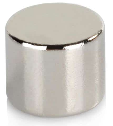
1) A cylindrical magnet
2) An appropriately dimensioned pipe whose internal diameter should be just slightly higher than the outside diameter of the magnet.
3) A few feet of magnet wire or super enamelled copper wire having a thickness of around 30SWG.
4) 4nos of 1N4007 rectifier diodes for making the bridge rectifier, and a 220uF 16V filter cpacitor which could be ideally a super capacitor
5) 1 LED rated at 1 watt, ultra bright, preferably an SMD type
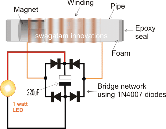
The Circuit Layout
Building Procedure:
The procedure for completing this simple shake-a-gen or a shake powered flashlight circuit is very simple.
Wrap the wire around the pipe as shown in the following figure and secure the wire ends through the end pin holes appropriately drilled on the pipe.
You can wind multiple layers of wires one over the other for acquiring higher current from the unit.
Once the winding is done, slide the magnet inside the pipe, and seal the two ends of the pipe with epoxy glue, preferably do this with a piece of foam stuck at the inner side of the two ends of the pipe.
Let the unit dry until the epoxy has hardened fully.
Next, wire the ends of the coil with a bridge rectifier, a filter capacitor and an LED.
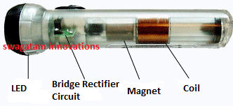
The set up is complete now, and the unit is ready for shaking.
Now it just require holding the pipe within your fingers and giving a quick to and fro shake.
As soon as this is done, the LED could be seen glowing brightly, and the illumination sustained even after the shaking is stopped.
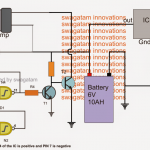
Incorporating a Joule Thief Circuit for Maximum Brightness
The illumination period could be significantly increased by adding a "joule thief" converter with the bridge rectifier, as shown in the following figure, however when this concept is utilized, the number of turns must be reduced and instead more number of parallel turns must be added to the winding, because here the current needs to be relatively higher so that the Joule thief circuit is able to convert it into a sustained amount voltage for the LED
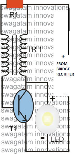
The number of turns in the above joule thief could be with a 20:20 ratio, or other proportions could also be tried for getting a preferred customized amplification.
Coil Specifications for the shake powered flashlight
The coil specifications for the first circuit is not critical, as a rule of thumb make the coil length 3 times the length of the magnet.
The number of turns in the coil determines the voltage level while the thickness decides the current magnitude.
Preferably, instead of a single thick wire many thin wire strands must be used for acquiring proportionately higher level of current through the system.
This could be possibly achieved by using a standard 14/36 flexible insulated wire and wrapping a single layer over the pipe, or a couple of layers could also be tried for boosting the voltage along with current.
As suggested earlier the diameter of the magnet must be just slightly lower than the inner diameter of the pipe so that the magnet is able slide effortlessly in response to the shakes, and additionally ensuring a minimum possible margin between the coil and the magnet. This gap decides the efficiency factor of the system, lower gap ensures higher efficiency and vice versa.


Comments (33)
Hello sir, please I don’t know the mechanism working, I winded 1500turns on a laminated core,when I tested the winding with analog meter, on touching both ends, there was a massive electric shock. Please kindly explain.
Hello Daniel, if you are getting a massive electric shock that means your coil is working perfectly, however this high voltage can quickly damage your LED or the capacitor, so you may have to reduce it until it reaches an acceptable level.
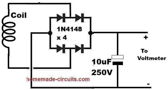
Please try the following setup to check the maximum voltage from your coil, and reduce it to a lower level appropriately…
In this circuit you share in the comment section, please what is the advantage of using in4148 diode instead of in4007 diode as rectifier diode
Daniel, the 1N4148 has slightly lower voltage drop than a 1N4007 diode according to my practical experience.
Thanks sir for your reply, Please, I want the high voltage from the scenario I explained but I don’t know I to design it practically without the meter, please sir, guide appropriately, and explain the mechanism.
Thanks sir, Swagatam.
Daniel, sorry, I could not understand your exact requirement. Please elaborate.
The high voltage is generated due to the high number of turn in the coil inside a moving magnetic field. The voltage level will be directly proportional to the speed of the movement of the coil and the number of turns in the coil..
Sir, I meant I winded 1500turns on a laminated core,when I tested the winding with analog meter, on touching both ends, there was a massive electric shock without connecting any power source, just the meter to check the resistance.
Is there a circuit that can simulate the occurrence with the meter and the coil on laminated core.
Daniel, it is happening because the tiny electrical current from the meter probes are getting boosted through the coil, that’s all.
Please use an analogue, needle type voltmeter, and you will find no such thing happening.
Thanks sir, please how can I simulate such boosted current manually with homemade circuit without using the analog meter
Daniel, The current is not boosted, the voltage is boosted, current is reduced. If you apply a pulsating DC across any coil, the coil will provide an amplified reverse back EMF voltage, boosted to higher level.
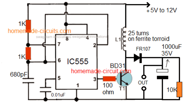
You can try this example circuit to replicate the high voltage output from your coil:
Thanks sir, please how can I use this output for 36v output, any modifications?
Daniel, You will have to adjust the number of turns of the coil winding until the 36V level is achieved.
Hello and good time Mr. Swagatam
I hope you are fine
I am Mehdi from Iran
You have a very comprehensive and good website
A few questions about the Shake Powered Flashlight
https://www.homemade-circuits.com/shake-powered-flashlight-circuit/
I wanted to make a flashlight
Of course I have a cylindrical Neodymium magnet N42 60✘30
Diameter 60 mm and height 30 mm
The flux in the center of the magnet is about 4100 gauss.
And the questions:
1. What type of copper wire should I use for maximum productivity and energy production?
Should the number of turns of the wire be greater or the thickness of the wire?
2. Can 2 or more coils be used? Like the picture below?
3. What should be the size of the pipe?
4. How important is the speed of the magnet in the tube?
5. How much energy is produced with the above magnet and in the best case of winding in one movement of the magnet? roughly?
thank you
I am waiting for your answer
Thank you Mahdi, I appreciate your interest very much.
Unfortunately it will be difficult for me to answer all your questions because I do not have the necessary formulas to calculate the parameters.
As far as I know the copper wire should be super enameled copper wire and should be very thin, around 32SWG.
I think the best way to proceed is by trial and error method, or by purchasing a new readymade flashlight and by checking its internal construction.
But shouldn’t I at least get a flicker without the rest of the circuit?
Yes it should, you can try checking in complete darkness. But the shaking process has to be very fast.
If I connect the two ends of the magnetic copper wire to an led light and shake the magnet in the tube, should the light flicker each time the magnet passes the coil? If so, what could be some reasons why this does not happen?
You must have a bridge rectifier and a filter capacitor to make the LED illuminate. You can also incorporate the joule thief circuit for better response.
I have a system capable of the following:
2lbs of magnets ( assume 50 n52 .5″x1″ )
vertical oscillation
1 coil pass measures ( 200mV 100mA )
10 mag per strand x 10 coils per strand x 5 strands x 2 passes ( down up )
= 1000 pulses per cycle @(200mV 100mA per pulse)
question1: how to store and combine each coil output to single battery ( would joule thief on each coil make sense? )
question2: how to calculate the kWh?
please reach out anytime/anyhour!
9497026170
Add the coils in series and connect a bridge rectifier across the ends of the series coil terminals. Also add a 1000uF/25V across the +/- of the bridge output…joule could be added after the bridge for boosting the output volts.
30 swg wire how many turns need
200 to 400 turns, do some trial and error and check which one gives the best results
sir can 220uf capacitor replaced with 1000uf
if yes what may be the peformance
Manunath, if your inductor and magnet are able to gnerate more power than 220uF can store then surely you can use 1000uF, otherwise it won’t be useful
yes that may be possible if all the parameters are appropriately optimized…
sir, does extending pipe and winding increases efficiency, and that can i include rechargable battery to that
thank you sir
manjunath, efficiency can be increased by making the gap between magnet and the pipea as minimum as possible, by using multi-fiber wire, and by making the inner surface of the pipe as smooth as possible,
increasing winding will increase voltage with respect to the shaking speed.
yes you can include a rechargeable battery in the design
My intention is to increase the time of glowing
can i include 1.5v rechargable battery to this . if yes how can attach
you can use it, connect it where the LED is supposed to be connected. but if LED is also connected the cell might not get optimally charged.
Hi Swagatam,
Good day. Your site is such an excellent source of information to those who are electronic enthusiasts.
I'm sorry, I am fresh new here. I don't find your request page. But anyway, I want to request you a circuit, I know it's not common as of this time. An Inverter type airconditioner utilizes a DC compressor motor and a new technology circuitry. Many people are aware this technology is still very costly, not everybody can afford. I am trying to find a way to convert a normal AC compressor to run at lower speed once the temperature setting is achieved, thereby copying the inverter type principle. This is to avoid the on/off operation of the compressor which is eating much power and I am talking about energy saving. I have read somewhere a thermistor might be useful as a temperature sensor for this circuit. With your thousands of knowledge in electronic circuit, I believe you can make one like this.
I appreciate there is such website like yours.
Best Regards,
Paul
email:casem.apolinario@chiyodacorp.com
a_casem@yahoo.com
Thanks very much Paul,
I think it can be accomplished using a VFD technology which I have already covered in this website, however since your suggested application will require an automatic adjustment will need to be a slightly different from the one which I have published.
I will try to figure out the design and will post it soon for you.
Hello,
Good day. Your website is so much helpful to those who are electronic enthusiasts.