In article below explains the control circuit for an automatic tennis ball throwing machine, designed to throw a tennis ball through a mechanized catapult machine, controlled with powerful motors.
In this article I have explained the motor control circuit which will toggle the catapult mechanism back and forth, with a 2 second time interval, while the machine is in the throwing mode and the standby mode.
The circuit was requested by one of the avid readers of this blog, Mr. Obi, as I have explained below:
Being a mechanical engineer, i have not much knowledge about electronics. But i always fascinate how simple components does the trick and operates from simple to complex logics.
My intention is to build a tennis ball throwing machine. My requirements are, once the machine turns left it should press the limit switch and in turn should stop the turning motor (M1) only for 2 seconds and the should start the motor again in order to crank the machine towards right(changing of direction will be done by mechanical crank and levers).
And then same thing should happen again over the right side. Also at the same time, the either limit switches should stop the supply to a proximity sensor installed at motor M2 only for 0.5 seconds and then the supply should start again as normal. Supply would be 12V dc. Kindly advise, thanks..
The Design
The basic working idea of the tennis ball throwing machine circuit is actually simple. A motor is allowed to rotate at full speed from an initial starting position to a finishing stop position, both the positions being attached with a push button or a limit switch which stops the motor as soon as it reaches the respective positions of its rotating path.
Once the motor shaft reaches the the above explained start and end positions, the motor is halted for 2 seconds, and then forced to rotate on the opposite direction, causing the motor to flip flop back and forth with a 2 second time lapse between the reverse/forward movements.
To implement the above explained high speed back forth movement of the motor we actually need a couple of circuit designs.
The first circuit stage is a relay circuit that toggles the motor back and forth, while the second circuit is a 2 second timer circuit which ensures that the motor halts for 2 seconds between its to and fro movement.
The Bidirectional Motor Relay Controller
The bidirectional motor controller I have explained below rotates the motor back and forth continuously, which in turn is used for enabling motor mechanism to throw the tennis ball in the specified direction.
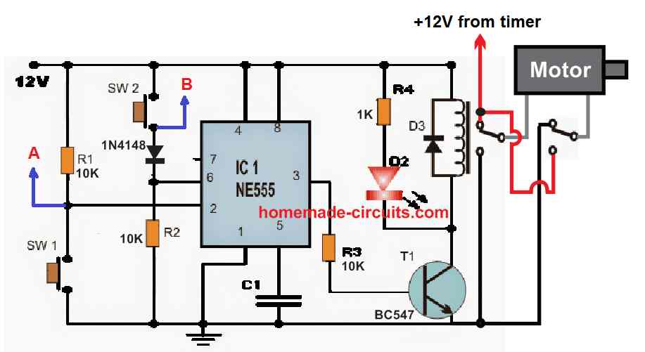
Referring to the above 555 set-reset diagram, SW1 and SW2 are arranged as the limit switches for the start and the finish limits of the motor rotation.
Let's assume the motor is at the SW1 end, and the SW1 is pressed in the course of the action.
With SW1 pressed, the IC 555 activates and switches ON the transistor T1. The transistor T1 actuates the DPDT relay and flips the motor rotation to the opposite side.
However, the motor is unable to revert immediately, because pressing SW1 also activates a monostable timer, which disconnects the power to the above motor relay.
The Monostable Timers
The monostable timers are shown in the following diagram. After the SW1 id pressed, the right side monostable timer activates, which switches ON the output pin3 of the respective IC 555 timer. The pin3 activates the SPDT relay disconnecting the positive supply to the motor.
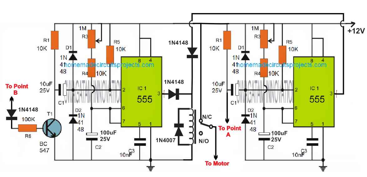
However, after about 2 seconds, or as per the set time of the monostable timer, the IC 555 switches OFF its pin3, causing the relay to return to its N/C point.
This instantly supplies the positive supply to the motor relay allowing the motor to start moving towards the opposite direction.
As soon as the moves starts moving, it releases the SW1, and when the motor reaches the other end of its rotational path, it presses the SW2 limit switch.
SW2 now resets the motor control circuit so that the motor can again rotate to the opposite direction.
However, just like the above case, SW2 also activates the second monostable timer on the left side, which causes the left side IC 555 to activate its pin3, which in turn causes the SPDT relay to disconnect the positive supply to the motor relay.
After about seconds the left side monostable's time lapses, switching Off its pin3 and the relay returns to its N/C point.
This instantly connects the positive supply to the motor relay and the motor now yet again starts rotating in the reverse direction towards the SW1 switch.
The above procedure keeps repeating, allowing the motor to move in the reverse forward direction, and enabling the motor mechanism to implement the tennis ball throwing action swiftly.
This concludes the explanation for the making of a tennis ball throwing machine circuit, if you have any related questions, do feel free to express them through the comment box.


Questions & Answers
That’s a amazing topic, I dindt find another topic in last years.
I’m new doing this, its really works? could someone helps to create it?
Thank you.
Thank you, and glad you found this topic useful.
This circuit was designed with my own knowledge and understanding and I believe it will work if it is build correctly and stage-wise.
Swagatam, I’m a Beginner Tennis Player and work with IT as well.
Its possible you help me to create a Tennis Ball Throwing Machine?
I started to learn Arduino but I need to learn much more hehe.
Hi Fernando, as you can see that the above circuits are quite complex and has many critical parts and stages which can be very difficult to build and set for any newcomer. So I would not recommend this circuit to you since you are a beginner. You must first try building smaller circuits, until you are an expert in the field.