So far in this website we have studied LM317 based linear power supply circuits, here I have explained how an LM317 can be executed as a variable switch mode power or SMPS with zero loss.
LM317 as Linear Regulator
We all know that an LM317 IC is internally designed to work as a linear voltage regulator IC, which has a serious drawback of power dissipation through heating. Moreover such topology also requires the input to be minimum 3V higher than the desired output, adding further restrictions to the given regulator configuration.
Here I have explained how the same IC could be simply implemented as a 0-40V variable power supply using SMPS topology and therefore eliminating the losses mentioned in the above paragraph.
Modifying LM317 Circuit into a PWM Switching Regulator Circuit
The LM317 variable SMPS circuit explained here effortlessly converts an ordinary LM317 IC into an inductor based switching regulator power supply counterpart, as exhibited in the following diagram:
Circuit Diagram
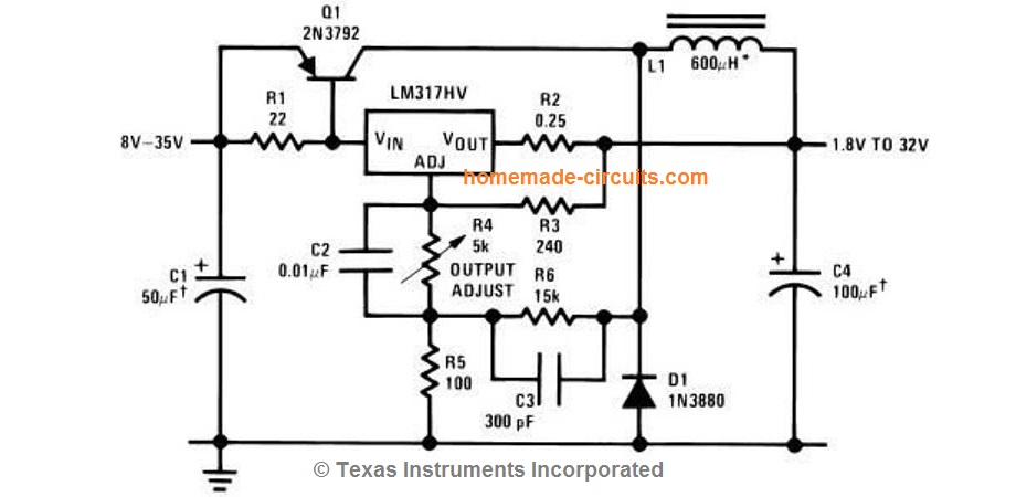
Referring to the above shown diagram we can see that the LM317 is configured in its usual variable regulator mode but with some additional parts in the form of R6, C3, and D1.
We can also see an inductor attached with D1 and an associated power BJT Q1.
How it Works
Here the LM317 IC performs two tasks together. It varies the output voltage through the indicated pot R4, and in turn causes a PWM to initiate for the base of Q1.
Basically, the introduction of R6/C3 transforms the LM317 regulator circuit into a high frequency oscillator circuit, forcing the output of the LM317 to switch ON/OFF rapidly with a varying PWM, which is dependent on the setting of R4.
The BJT Q1 along with the inductor L1 and D1 forms a standard buck converter circuit which is controlled by the above explained PWM generated by the LM317 circuit.
This implies that while the pot R4 is varied, the voltage pulse width developed across R1 also varies proportionately causing Q1 to switch L1 in accordance with the varying PWMs.
Higher pulse widths enable the inductor to produce higher voltages and vice versa.
Capacitor C4 makes sure that the fluctuating output from L1 at the output is adequately smoothed and eliminated, this consequently enhances the ripple current into a stable DC.
In the proposed LM317 switch mode power supply circuit since the IC LM317 is not directly involved with the handling of the load current, it's restricted from dissipating current, and thus ensures an efficient regulation of the high input voltage into the desired low output voltage levels.
The design also allows the user to upgrade the circuit into a high current SMPS circuit simply by changing the Q1, L1, D1 rating as per the required output current specifications.
L1 can be built by winding bifilar enameled copper wire over any suitable ferrite core.
Although this LM317 SMPS circuit promises a near zero loss output, Q1 must be mounted on a heatsink and some degree of dissipation may be expected from it.
Interesting Feedback from one of the Avid Readers:
Mr. Swagatam:
I am a retired EE, but continue to have an interest in various areas. Happened to come across your website when I was researching power supplies using LM317.
Saw the interesting switch mode power supply schematic using the LM317.
As it turns out, the exact circuit shows up in the 1978 National Semiconductor Voltage Regulator Handbook, with additional verbiage to explain its behavior.
However, I found it even more helpful to simulate the circuit using LTSpiceVII (which is free to download and use) to get a better idea of how the circuit operates with component value changes.
Anyway, I decided to scan the two pages from the 1978 Handbook and email to you in the event you care to post them with the schematic for others who might be interested in a little more detail.
Regards,
Denton Conrad
Raleigh, NC
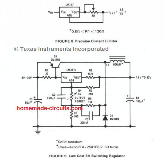
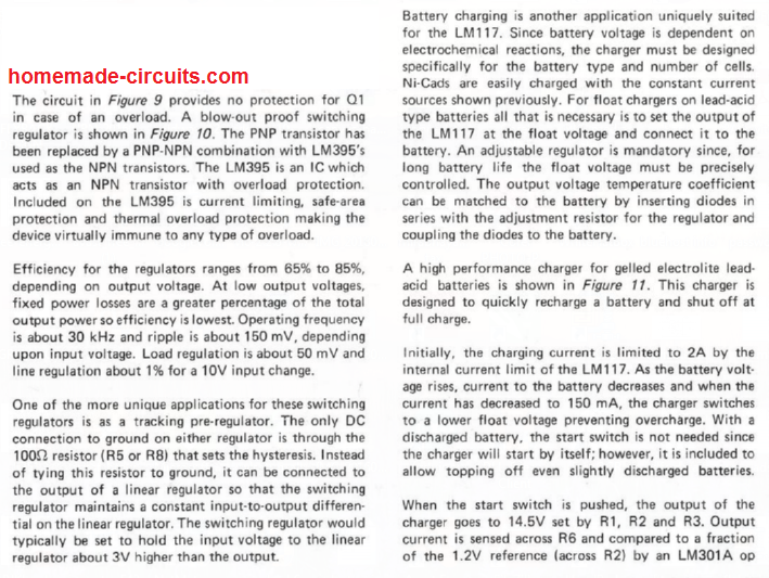
Complete article can be found in the following pdf link:
https://www.homemade-circuits.com/wp-content/uploads/2023/05/LM317-switching-regulator.pdf
Another Feedback from a Dedicated Follower of this Blog, Mr. Prashanth Suvarna
As a dedicated follower of your work, I would like to share some observations related to the previous discussion.
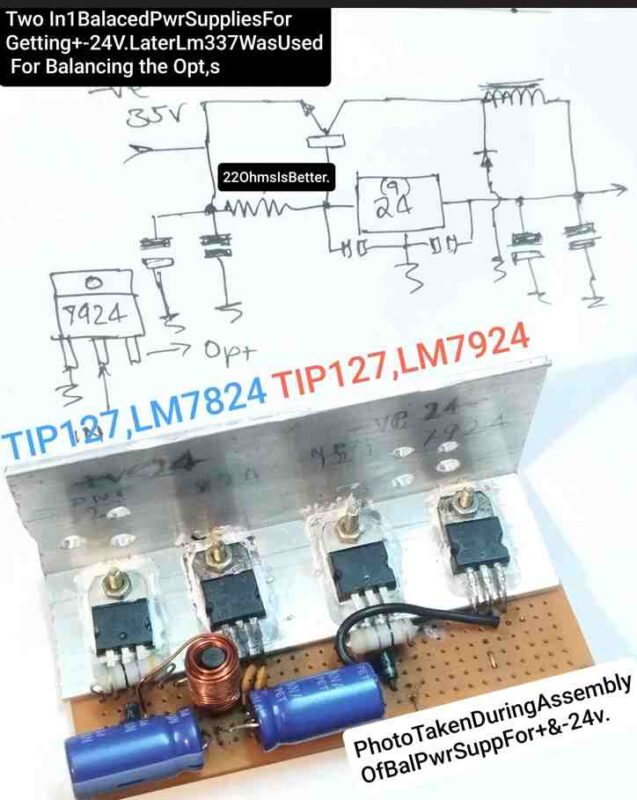
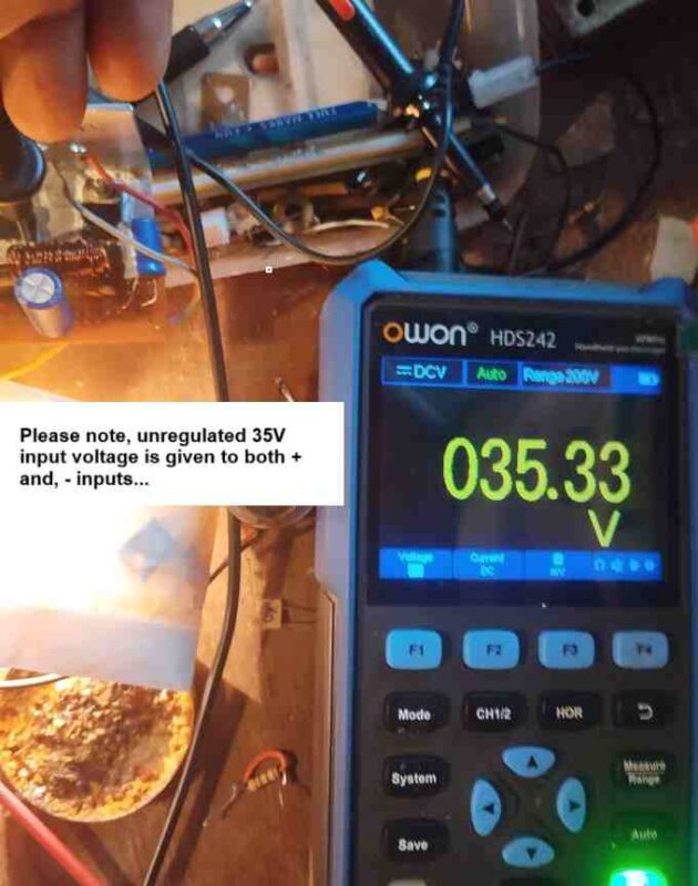
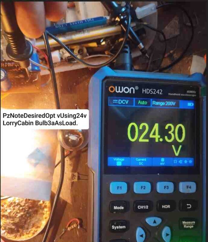
I needed a balanced ±24V power supply for an output transformer (OPT) stage that only needed ±24V, not the 39V given by the original amplifier. I modified your basic circuit design to incorporate a negative switcher. One of the driver ICs is variable, which allows for accurate voltage balance.
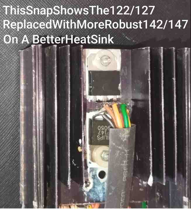
One major advantage of this method is the substantial reduction in heat dissipation when compared to a similar circuit working in linear mode. The smaller Darlingtons (122/127) first concerned me because of their failures. They failed even without overheating. To remedy this issue, I replaced them with (TIP)143/147, which functioned excellently.
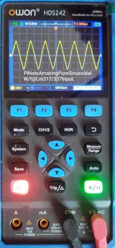
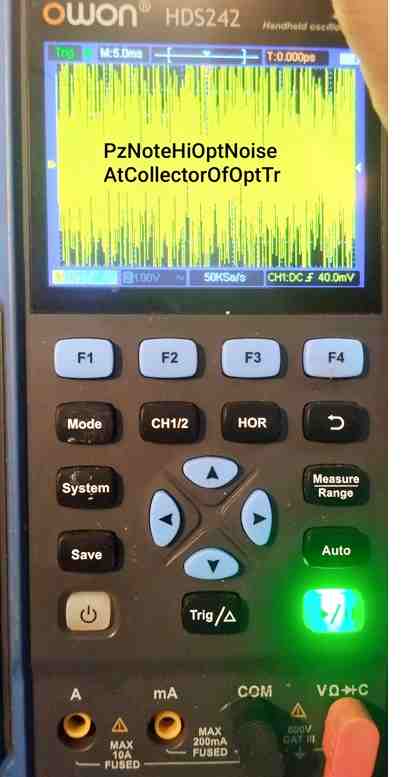
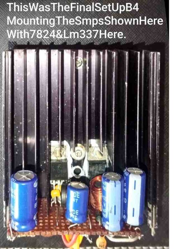
Please find the attached pictures below, which were taken while analyzing the design.


Questions & Answers
Since 50uF capacitors and 240R resistors are not available in shops, can we use 47uF capacitors and 270R resistors
Yes, no issues, you can use them…those values are not too critical.
This is the high voltage regulator called maida regulator, it can up to 170v input
Thank you, it looks good, but I am not sure how this can be converted into a buck converter using an inductor.
Please can the above lm317 buck converter be modified like this to take in high input voltage and regulate to produce current up to 10amps with corresponding input power. Thanks Mr Swagatam
Hi Daniel,
10 amps may be possible by modifying R1, Q1, L1, but voltage cannot exceed above 60V.
please for 12v battery, which value should I set the charging for optimal efficiency with 60v input
You can use 14V max.
Thanks sir, please between using appropriate specs of voltage and current for a charger and converting excess voltage using buck converter, which is more effective and efficient for charging
That depends on your power supply source, if you have the exact spec then that is ideally suitable, but if you power supply does not match the battery spec, and has higher voltage and lower current, then using buck converter becomes a necessity.
Where is figure 10 in the latter part of the article?
It is not available with me. You may have to check the original datasheet for it.
Thanks Mr. Swagatam! Cct is working perfectly. Suggest me upgrade , how can I add more components to make it more efficient.
Thank You M.Ahsan, glad the circuit is working now.
However, I cannot suggest any upgrade except for the transistor and the coil, because rest all are designed by the manufacturer and cannot be upgraded or modified.
For the transistor and the coil you can upgrade these by increasing their current handling capacity appropriately, which will allow you to increase the output power of the circuit.
Thank u sir, for your most valuable feedbacks.
You are most welcome M. Ahsan
Sir, will flyback generated by inductor L1 make some effect for other semiconductors after switching off the power? can I add some protection? r not necessary ?
The voltage generated from L1 will be stored inside C4, so it is fine no external protection is necessary. You can increase the value of C4 to 1000uf if possible.
sorry sir for again, in present scenario above what should I do? should I increase the thickness of coil or decrease? for overcome heating and voltage dropping problems less then 2 amp?
You can try changing the transistor. You can perhaps try TIP2955. Yes increase the coil wire thickness to 1 mm at least.
hi sir, today I tried to arrange this cct. I set it to 24 v input and 15 output. but the Q1 TIP36 got heated at load of 2 amp. and LM317 got burn. then I tried LM339 in place of LM317. this LM339 working perfectly without heating. but still Q1 is heating, with load.
and when I decrease the current of power supply, the output voltages drops from 15 to 9 V. .. and Input drops from 24 to 12v, with load. is it normal thing with decreasing input current? plz guide.
cct arrangement with some replacements.
a)D1– Fr107 instead of 1N3880
b)Q1– TIP 36 instead of 2N3792
c) inductor I think as it is. 600 u H
**and especially what can I do to overcome the heat of Q1?
thanks.
Regards:
M.Ahsan
Hi M.Ahsan,
The LM317 is internally protected from output over current and short circuit and over heat, so it should never burn under any circumstances unless the input voltage exceeds 40 V. Also, the TIP36 is rated to handle up to 25 amps so it should not heat up at 2 amps. I think the parts you brought might not be original.
Yes LM338 being rated at 5 amps it will be cooler than LM317.
Yes if you decrease the input current then the output voltage will drop since the load is not getting sufficient current as per its specifications.
You can supply any amount of current at the input that will not cause any harm to the IC or the transistor, but the voltage to the load must be correctly adjusted so that the load and the transistor are not over loaded.
So you just have to take care of the following things:
Input voltage should be ideally below 40 V
Input current can be any value even upto a million amps, that is irrelevant.
Output voltage to the load is crucial and must be accurately set as per the load specifications..
Output load current specifications must be in accordance with the transistor specifications…2 amp is very less for TIP36 and it should not heat up. It can heat up slightly but not too much.
Make sure the inductor wire gauge is at least 1 mm or 2 mm thick.
thank u sir for ur valuable reply.
My pleasure!
sir, Can I use 2n3055 in place of 2N3792?
and I am having problem to getting tantalum capacitors, plz suggest the replace. Regards, M.Ahsan
M. Ahsan,
2N3055 is an NPN transistor so it cannot be replaced with 2N3792. You can try TIP2955 or TIP36.
Tanatalum capacitor is recommended, but if don’t get it, you can use other ordinary type.
thank u sir , u solve my problem.
I am glad to help!
it’s very useful. i like it. but u didn’t mention the wattage of resistors used in this cct. plz mention the wattage of resistors used in cct.
Thank you! R1 and R2 can be 1 watt rated and rest of the resistors can be 1/4 watt rated.
thanks bro for ur quick reply.
That verbiage from the National Semiconductor Voltage Regulator Handbook was not descriptive of the circuit in question, it was descriptive of the next illustration, that of a much improved version using an NPN-PNP arrangement (a 2N2905 and three LM395s with internal overload protection) in place of the PNP transistor.
Hi Swagatam
I wrote to you regarding using IN 4148 in parallel but I think I made a mistake,
I thought they are 1amp diodes but realized they are only 150 ma……. sorry about that. I can’t use them.
Thanks again for all your help Swagatam
All the best
Regards
Vee
OK will do, no problem…
Hi Swagatam
Can I use 4 or 5 IN4148 diodes in parallel as they are fast switching diodes but only rated as 1 Amp will the voltage be affected
Thanks
Vee
Hi Swagatam
Thanks for your reply regarding the diode but you didn’t tell me what I asked you about the inductor coil, please let me know about the winding .
I have a ferrite bar about 1” long and should the the layer of windings be insulated with tape between the layers of windings
Thanks Swagatam
Regards
Vee
Hi Vee, Since the wire itself is super enameled, and since the turns are for a single winding therefore insulation is not needed between layers…
Hi Swagatam
Thanks for your reply
I check the coil again, do I have to use insulation tape between the layers of the coil.
The Ferrite core bar is about 1” long with the wire around it.Is the RG2Z diode ok to use does this also matter.
I tried many places but cant get the IN 3880 diode or the equivalent, I can’t understand why.
Thanks again
Vee
GE Sir, regarding available of the door in Q, I wish to point out that you can use a more easily available BA159 as it works perfectly well and is commonly used in many TV,s.
Hi Vee, the diode current must be higher than the required output current. If the output requirement is 2 amps, then the diode must be rated at 4 amps and so on, otherwise the diode may heat up….
Hi Swagatam
Thanks for your reply, I did try the circuit with a load if upto 750 ma and I sent you the readings as you suggest I shall try to get thicker gauge wire and try once the situation gets better with the stores.
The only thing is what do I do about the C3 capacitor, why is cutting of the power
Anyway shall keep trying, if possible please let me know what I could do
Thanks immensely once again for all your help
Vee
No problem Vee, let’s hope you ultimately succeed with the project, but the 300 pf is crucial in the circuit since it determines the frequency of the buck oscillator….I think your coil may have problems, please confirm its value with the inductance meter and make sure it is rated at 600 uH, and everything else in the circuit is exactly same as the diagram.
Hi Swagatam
I happened to have a 330pf and tried it out but when i switch on the power comes on for a second and goes off, I don’t know why but when I remove it, the power stays on. What should I do
I further tried with a load of 1.77 amps and its fine the temperature etc
When I tried with 2.00 amp load the inductor temperature went up to 80*C and I switched off immediately, guess i have to use a thicker gauge wire.
Thanks
Vee
Hi Vee, I think a load will be required while testing the results. Yes you can try increasing the wire thickness, or try the existing circuit with smaller load, and see the results
Hi Swagatam
The diode I used was RG2Z this is the only one I had instead if the IN3880 Is this ok
Sorry to bother you again
Thanks
Vee
Hi Vee, the diode will work up to 500 mA current after that it may start heating up
Hi Swagatam
Thank you so much for your immediate reply, shall see what caps I have to match the 300 pf. Should this be exactly 300pf or anything close to it …. what value
I forgot to tell you the power supply I used is a transformerless 24.5vdc /6 A
Are the temperatures ok which I mentioned……please let me know
Thanks again
Vee
Hi Swagatam
Guess I have some good news
I tried out the SMPS circuit and it seems it worked. I shall give you the details of the parameters I observed please let me know if they are OK
Input voltage from power supply- 24.5Vdc
Output volts of SMPS on adjusting -12.54vdc
I used 12v/550ma bulb & a cooling fan 12v/ 1.05amps (Totally about 1.54Amp load)
After 10 to 15 minutes
Temperature of
MJE 2955 was 39/41*C with heat sink
LM 317 was 27/29*C with a small heatsink
Inductor coil was about 34* C
Out put was steady
Are these parameters normal and is the SMPS working the way it should
NOTE: I did not have the 300pf ceramic capacitor which is in parallel with the 15k resistor , I used one of little lesser value but the LM 317 was heating up so I did not use any.
I’d like to send you a video of the temporary setup but don’t know how to get it to you
Please let me know your opinion
Thanks for you help Swagatam
All the best to you
Vee
Hi Vee, that sounds great, and the results look impressive, however C3 may be an important part which should not be be missed, in fact it is responsible for the oscillation, so I think you must include it. If you don’t have the exact value, you can adjust the value by adding a few known capacitors in series or parallel.
Once you add the 300pF, and if you get the adjustable feature from 3V onward, with load and without heating up the devices then I will consider the experiment to be 100% successful.
Hi Swagatam
Thank you very much fir your reply, shall try out the circuit.
All the best to you
Regards
Vee
You are most welcome Vee!
Hi Swagatam
I happened to find among my stuff a 612 &655 uH inductors which I used to use for my electronic fan regulators but the wire gauge is 0.5. /0.6mm and I have a RG2Z & RG4Z diode can I use this in place of the IN 3880 diode and also the inductors I have in the switching power supply here in this article ……. I think you said I could use the MJE 2955 in place of the transistor 2N3792 and iI have a preset which reads 7.8 k
Please let me know if i can use these items to tryout the variable SMPS with the input from a 24v/6A smps
Still cant get the exact parts due to closure of all these stores.
Thanks
Vee
Hi Vee, I think you can try those parts just for testing sake…..this will let you know whether the basic circuit is working or not with a low current set up….if you find the circuit working with lower current you can afterwards change the coil with a more heavy duty one for getting higher current output
hi Swagatam!
I’m having problem to getting exact value of diode in cct. kindly plz suggest me any other value of diode.
Hi M. Ahsan, you can try FR107 or BA159 diode for D1.
Dear sir, Thanks a lot for ur kind reply.
Hi Swagatam
Thank you immensely for all you help and guidance. I shall try to get all the components that are required to build the LM 317 SMPS circuit once the shops are opened again and shall let you know how it went .
Till the next time all the best to you,bless you
Kind regards
Vee
My pleasure Vee, I wish you too all the best!
Hi Swagatam
In the manual it does not show or mention what the 36 volts max is but in the pictures on the net it shows “ Capacitance test sockets” across the two sockets where it says max 36 volts what are these sockets for, does it mean we can test capacitors with the two leads in these sockets and is this the volts of the capacitor value
Thanks
Vee
Hi Vee, I saw the picture of the LCR meter, and also saw the 36 V marking on it.
It seems the meter is suggesting not to check capacitors which may have a stored voltage of over 36V….so before testing any capacitor make sure to discharge the capacitor first, and then connect the probes to it.
Hi Swagatam
Today I received the LCR meter its a PROSTER Model BM 4070 from Amazon and I tested out some inductor coils I had but they are only 145 & 138 uH wound on a common circular core.
In the SMPS circuit in this article we need a 600uH inductor, if I series the coils which would be 483uH could I use this what would be the result, even the equivalent diode you told me in your earlier message i cant get due to all these lockdowns I only have the IN 5408.
I want so much to build this SMPS circuit but the parts are the problem.
I also want to send you a picture of the meter and clear a doubt a label on the meter that says 36 volts Max,what does it mean, can I send the picture by email to you, but i dont have your email , awaiting your reply
Thanks
Vee
Hi Vee, the inductor must be almost exact as given in the diagram. If it is 630uH then it can be 600 uH but not too far away from the actual value.
Now since you have an lCR meter with you, you can try building your own inductor by winding a 1mm thick super enameled wire over any small ferrite rod or ferrite core.
It will be difficult for me to understand the specifications of the meter just by seeing the picture….if you have the manual or the booklet of the meter you can write the specs here, I will try to understand them and explain if possible.
36V may be the maximum volts the meter can tolerate while measuring anything with the power supply ON. However the inductance must be always measured without any power through the coil
Hi Swagatam
One more question
I purchased a variable SMPS power adapter 9v -24v /3A with an LED display from Amazon .
This adapter does not have any heat sinks, so does it mean they are using a circuit like the link you sent me earlier with opto coupler and it does not generate much heat the device gets a little warm
Just curious to know how this works. They do not have any with 9 to 24v //5A
Thanks
Vee
Hi Vee, yes if it is not generating much heat then it should be a SMPS design, because all linear regulators using transistors and ICs will generate heat
Hi Swagatam
Thanks for your reply and sorry fir troubling you with all these electronic problems.
I did go through the link you sent me about modifying an SMPS, it’s quite a tricky job anyway shall see what I can do or forget about the whole thing, I’ve seen a good LCR meter at Amazon and plan to get it. The inductor in the buck & boost circuit you sent me is a 600 micro henry inductor and should it have a current rating for about 6 to 10 amps, please advise, with this I won’t trouble you till I launch upon some other project
Thanks and all the best to you
Regards
Vee
No problem Vee, I am always glad to help!
yes, modifying an SMPS can be be difficult, that is why the LM317 based SMPS is the best option for you.
An LCR meter will be very handy in this situation, and will help you to build the specified coil easily.
You can use a 1 mm thick wire initially which must be super enameled copper wire, and will give you 2 amp current, for higher current you can take 3nos 1mm wires in parallel and wind them together on the ferrite core.
But first please try with a 1 amp version, if it works then you can change the transistor with TIP147 and go for the 5 amp version.
Hi Swagatam
Thank you for your kind reply, I don’t want to modify the SMPS I have ( that is the 24 volts/ 6A adapter) I want to use this as a power source and want an add on circuit from the out put of the one I have to make it a variable voltage bench supply.
I tried it with an LM317 & a 2N2955 with heat sinks but when regulated to 12 to 12.5 volts and with a load of about 3 amps the 2N2955 heat sink gets very hot, more than 60*C so I switched off the power. If the input voltage is reduced to about 18/20 bolts to the variable circuit the temp is around 45* C Heat sink size 3” x2” with additional fins
Can you suggest any circuit or what to do to reduce the heat ir lower the voltage to about 18 volts
Thanks Swagatam
Regards
Vee
Hi Vee, I will explained this earlier also that only a variable SMPS can be without any heat generation, if you use transistor or IC, then heat will be always generated. It cannot be avoided.
Hi Swagatam
I have a transformer-less power supply (may be smps) of 24vdc 6 amps as input and i want to make the output variable from 3 volts to 24 volts dc . How can i do that, can you please email me a suitable circuit
Thanks
Vee
Hi Vee, modifying SMPS is actually not recommended for newcomers, because they have complex circuitry and is not isolated from mains at the primary side.
Still, for knowledge sake you can visit the following article, which will give some insight regarding how to modify an SMPS
How to Modify SMPS for Adjustable Current and Voltage Output
Hi Swagatam
Thank you for your reply
I have an half inch ferrite rod about 1” in length and about 22 gauge wire how many turns would I need to use to get the 600uH value.
Thanks
Vee
Hi Vee, the inductance value will need to be verified through a inductance meter or a basic oscilloscope, through some trial and error, it is difficult to calculate it using formulas.
Hi Swagatam
Regarding the SMPS Curcuit shiwn here the IN 3880 diode and the 600uH inductor is not available here
They have 220, 470, and 820uH inductors that look like resistances will any of these be ok or is there a current rating too for these and can i use sny other diode in place of the IN 3880 diode
Kindly advise and if possible send me a picture of the type of inductor I need to use with specs
Thanks
Vee
Hi Vee, those inductors are low current inductors and cannot handle more than 300 mA current. For enabling high current above 1 amp or two amps you will have to build it manually by winding the col over a ferrite rod or torroidal core using 1 mm enameled copper wire.
For the diode you can use FR107, or BA159
Will a pc817 work for the photo couple or do I need to make one with the photo resistor?
Hello Swag,
I have a transformerless power supply 24vdc, 10A and wana to use a circuit to regulate the voltage from 3~24Vdc with same rated current of the device(10A). Does it(above circuit) work in this case? If you have something better, kindly introduce it to me.
Thanks
Hello Mah, yes according to the datasheet that should be feasible. However, the PNP may have to be replaced with a TIP36 transistor
hello swagatam
what is the voltage of the tantalum capacitors of 50uf x? and of 100ufx?
hello franz, it can be anything above 60V
can i replace pnp transistor with npn transistor? and instead of connecting base of npn to input of lm317t i rather connect it to vout
try the last concept from the following article
https://www.homemade-circuits.com/how-to-make-current-controlled-12-volt/
Sir good morning! I can’t find tip127 sir could I use 2 tip 32 as darlington configuration? any suggestion for any parts changes Sir? tnx!
Jindro, try a single TIP32 first, if it doesn’t work efficiently then you can upgrade it into a Darlington with a 2N2907 transistor
Hello Swagatam,
I first want to say I enjoy reading your articles and how toys. I’ve watched you on YouTube and read your Instructables for a long time now and they are vey informative.
I have a question about power and voltage in this circuit, how to apply the changes and if this would work for a diy bench top variable psu?
If I were to change q1 to a higher current transistor, do I only need to satisfy l1 and d1 voltage and current requirement for the circuit, or is a consideration needed for the base current of q1 in relation to lm317’s output driving q1’s base?
I am still a novice electronics hobbyist, and though I have firm understanding of application and mechanics, the equations are still elusive.
Thank you for all of your wonderful advice and instruction.
H. Foster
Thank you H. Foster, I am glad you liked my site, and I appreciate your involvement very much!
For acquiring more output current the base resistor of Q1 can be ignored to an extent, unless the output current requirement is significantly high, in that case the 22 ohms will need to be increased a bit and experimented. Or a Darlington BJT can be used for Q1 which will allow the 22 ohm value to be consistently without any change for any output current.
However, Q1, L1 and D1 will need to upgraded accordingly. For L1, the average wire surface area will need to be increased by winding bunch of thinner wires together, whose mass may be equivalent to the calculated single thick wire’s mass approximately.
Q1 rating will also need to be enhanced as per the required output amp specs….
Similarly D1’s current handling capacity will need to be upgraded as per Q1’s specs.
If you have any further questions, please feel free to discuss with me here…
I was thinking on using 2n5683 or MJ11015 to get up to 30 amps. I plan on using it in this circuit with a computer psu to make a diy variable bench power supply output. I believe the MJ11015 is a Darlington, not sure about the other. Am I exceeding their specs for this application or would line be better than the other. They are both inexpensive, which is what I’m going for. ?
And I’m correct in thinking I need a pnp, not an non, yes?
Thanks again for the assistance.
yes, it should be a PNP, the MJ BJT is Darlington but an NPN, so it won’t work.
2N5684 seems like a better fit, you can find the datasheet here
https://www.onsemi.com/pub/Collateral/2N5684-D.PDF
although it is not a Darlington, can be modified with another attached PNP such as TIP32 for converting it into a Darlington pair.
Sir can I use tip127 for q1? I want to build this for 5 li ion batt parallel charger or cellphone charger. Your other circuit is better but parts here in my town is so hard to find, I need simple and less parts like this tnx
Hi Jindro, yes you can try TIP127
Thanks again for the discussion Swagatam. I was looking at the mj11015g specifically because it is a pnp in a Darlington setup. Here’s the datasheet link at alldatasheets – http://www.alldatasheet.com/datasheet-pdf/pdf/426442/ONSEMI/MJ11015G.html
This way I don’t have to about current and voltage changes on the base and its resistor and its all in one package.
So am I correct in thinking the only additional considerations needed are for d1 and l1 current and voltage requirements? If I pick those to conform to the 30 amp max of q1 I should be set to build?
You have been most helpful and I truly appreciate it.
Thank you.
oh yes MJ11015g is a PNP, I am sorry, I mistakenly saw the search description for MJ11016 and assumed it wrongly.
In that case it can be definitely used for the discussed purpose, and the only factors that will need to be considered are L1, and D1, according to my knowledge.
you are absolutely correct with your conclusions regarding picking 30 amp specs for D1 and L1, and you can proceed with the assembly.
If you have more doubts, let me know, I’ll be most happy to help!
I have a projeck SMPS 48v 20 ampere ,, can you send me the schematic and component list via email ?? your help will be very helpful, .thanks sir,,
febryandespa@gmail.com
you can try to modify the following concept and get the required results
https://www.homemade-circuits.com/smps-2-x-50v-350w-circuit-for-audio/
hello sir,please i have a project i would love you to help me with.will love to e-mail the details to you.i wouldnt mind if you give me your email.thanks alot
Hello Mayokon, you can feel free to share it here through comments, I’ll try to help!
As a committed fan of your posts, I wish to add some of my observations to the above. I needed a balanced+-24-0-24 for powering a Opt stage that req only+24-24 instead of the 39 v that the unit was supplying to the original amp.I have used your basic circuit AAS fast as poss ex that I took it a step further and used it to make a negative switcher as well with one of the driver Ic,s being variable in order to realise a perfectly balanced voltage. Points worth mentioning is the dramatic reduction in the amount of heat dissipation compared to the same ckt working in the linear mode. The smaller Darlingtons122/127 made me quite apprehensive due to its failures twice even without heating, so they were imm changed to(Tip)143/147 which matched wonderfully.Ihave submitted the photos made at the time for your and the readers consideration.
Thanks so much Prashanth, for the interesting facts about this design, it is greatly appreciated!
I hope the readers will find this information very helpful while designing an LM317 IC based step-down switching regulator circuit.
Please let me how I can access the pictures that you have submitted…many thanks.
GdEvng Sir! Happy to hear your appreciation on my comments on the above. Now it was ONLY agree submition of my text that I realised that there was no option/provision for submitting photos, graphs etc as I could not locate the same. Pz guide me on the same Asap or send me your Em.I will post them imm. Thank you.
Good evening Prashanth! Thank you for your kind concerns!
Yes, unfortunately there’s no facility to upload images in this commenting platform.
But no worries, you can send them to my following email ID, I will check them out:
homemadecircuits
@gmail.com
Fine boss! I hv uploaded my observations as directed into your E-Mail homemadecircuits@gmail.com
Thank You Prasanth,
I have seen the images you sent in my email, the results look very nice indeed!
In your previous comment you mentioned “AAS fast as poss ex”….can you please tell me what it means?
Hello there! I’m sorry, but I remember sending a reply to u but I presume a it may have disappeared.As req I hv sent the snaps for your perusal and hope it clarifies many of the issues raised by some of your readers. I want your observations on the waveforms esp the some waves and the awful amount of noise at the transistor collector. But most of the noise has instead come down dramatically at the Lm317 opt due to its noise filters. BTW AAS fast as poss was supposed an abbreviation for AFAP (like ASAP) for as far as possible. thnx for pointing it out. This is because I prefer to use glide typing as is quick and convenient, by we should always approve matter b4 posting. Of traders wish to clarify anything in cnnx with my variation on the above circuit. they could get in touch with me by raising any issues as I will be glad to help.Thank you.My mail id is prashanth58in@gmail.com
Thank you Prashanth,
I appreciate your images and your feedback very much, and I have already posted them in the above article.
Please check this link, at the bottom of the article you can find all your images published with the required details:
https://www.homemade-circuits.com/lm317-variable-switch-mode-power-supply/
And none of your comments have disappeared, they might be temporarily not visible to you due to cache…
Sorry boss 4 being out of touch 4 such a long time. Uc I 4got the original link 2 reply 2u. That should have been only far/fast as poss (As applicable) The word creepy in as I usually use glide typing which throws up errors sometimes whic we are supposed 2 lookout 4 B4 opposing which I overlooked Sorry abt that. Btw I hope you will highlight the photos that you have observed on these columns as it will be of significant interest to concerned members of your coloum due to its offbeat application.I appreciate any comments or Q on the above and will be glad to be of any help on the same. Thank you.
Thank you Prasantha, for your kind feedback,
yes, understanding the text abbreviations or SMS language takes more effort…
I have added the photos which you sent me in my email.
I appreciate your observations and the experiments conducted on the above concept…
Many thanks…
replace Q1 with around 8amp rated device and adjust the pot for getting 4V/5amp
HI sir what about curent limitation of lm317 !how much power can give this socket ? what i have to do if i want to use li ion battery 3.7 volt whit this !thank you à lot !you are the best
Hi Rabie, current is supplied by Q1 not by the LM317, LM317 is used just for initialization of the buck converter and for the PWM control.
the output current is dependent on the inductor specs and the input supply current range.
Please tell me the wattage of all resistors. Ty
when not specified assume it to be always 1/4 watt rated.
Sir i have make an an inverter instant to rate at 220v but it rating at 320. what shall i do to decrease it to 220 ?? And later that i just observe that may be because i am using 6-0-6 transformer 12v battery but last time u say if going to use 6-0-6 transfer the battery also must be 6v so please how shall i reduce the battery from 12v to 6v ??
he wants to reduce 320V to 220V that's why I recommended the above method.
Wouldnt that be low voltage at the output if he is to use a 9v battery with a 12-0-12v transformer.
He has a 12v battery wouldnt it be best for him to use a 10-0-10v transformer?
Bashir, use a 9V battery with your 12-0-12/320V transformer, that will provide you with approximately 240V at the output
hello sir good morning
please I want to know, wher can someone apply the above circuit???
hello chucks, you can use it as a power supply circuit for getting an efficient power output and also as a solar charger. It can be also modified to work as an MPPT
Sir can I replace bjt/pnp transistor with MOSFET P-channel? sure i will try this after work ^_^
by the way sir is this circuit applicable also on LM7812 or 7805 regulator??
Thanks again Sir. Have a nice day.
Joseph, if you are using a mosfet then the 22 ohm resistor will need to be increased proportionately such that it develops the required 9V for the mosfet gate to trigger it satisfactorily.
No, it is applicable only with LM317 or LM338.