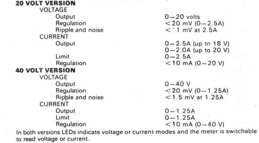
This multipurpose general purpose supply generates as much as 2.5 amps from zero to 20 volts or up to 1.25 amps from 0-40 volts. Current limiting is variable within the entire range for either output options.
By Trupti Patil
Power Supply Main Specifications:
AN IDEAL POWER SUPPLY must provide a voltage that is variable within a broad range, and that stays in the set voltage irrespective of line voltage or load disparities.
The supply must also be safe from a short circuit throughout its output and be able to restricting the load current to ensure that devices are not damaged by failing circumstances.
This particular project explains a power supply designed to deliver 2.5 amperes at up to 18 volts (up to 20 volts at lower currents). At the same time a few basic modifications will make the supply offer as much as 40 volts at 1.25 amperes.
The supply voltage is adjustable between zero and‘ the highest available, and current limiting can also be adjusted across the stipulated full range. The mode of operation of the power supply is indicated by means of two LEDs.
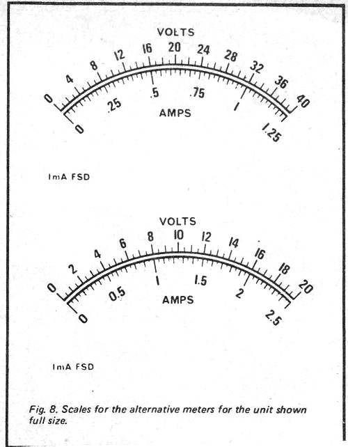
The one near the voltage control knob shows if the unit is in normal voltage-regulation setting and the one near the current limit knob shows if the unit is in current limit mode. Furthermore a large meter shows the current or voltage output as selected by a switch.
DESIGN FEATURES
While in our preliminary design stages we researched different types of regulator and the positive aspects and drawbacks of each to be able to pick the one which gives the top cost-effective functionality. The specific strategies and their features could be summarized as follows.
The shunt regulator:
This layout would work primarily for low power supplies around 10 to_15 watts. It offers excellent regulation and is internally short-circuit resistant however dissipates the full volume of power it is equipped to handle under no-load conditions.
The series regulator.
This regulator fits medium-power supplies approximately about 50 watts.
It may and is intended for higher power supplies, although heat dissipation could be a issue particularly at very high current with low output voltages.
Regulation great, generally there is minor output noise and the cost is comparatively minimal.
SRC regulator:
Ideal for medium to high power purposes, this regulator provides low power dissipation, though the output ripple and response time are not nearly as good as the ones from a series regulator.
SCR pre-regulator and series regulator.
The very best features of the SCR and series regulators are put together with this kind of power supply circuit employed for medium to high-power applications. An SCR pre-regulator is employed to secure an roughly regulated supply around five volts greater than recommended, accompanied by a suitable series regulator.
This lessens power loss in the series regulator. However, it is a lot more costly to construct.
Switching regulator.
Also applied for medium to high-power applications, this technique provides affordable regulation and low power dissipation in the regulator nevertheless is pricey to construct and possesses a high frequency ripple on the output.
Switched-mode power supply.
The most successful technique of all, this regulator rectifies the mains to operate an inverter at 20 kHz or even more. To lower or boost the voltage a low cost ferrite transformer is commonly employed, the output from which is rectified and filtered to get the preferred DC output.
Line regulation is very good but it surely has the downside that it is not able to conveniently be applied as a variable source since it is just adaptable over a relatively smaller range.
OUR OWN DESIGN
Our initial design principle had been for a power supply of around 20 volts at 5 to 10 amps output.
Having said that, in the light of the varieties of regulator readily available, as well as the costs, it was opted to limit the current to about 2.5 amps.
This approach helped us to employ a series regulator, the most cost-effective model. Good regulation was necessary, along with adjustable current limiting feature, plus it was additionally chosen that the power supply could well be workable right down to practically zero volts.
To get the final qualification a negative supply rail or a comparator that may run using its inputs at zero volts is essential. As opposed to using a negative supply rail we made a decision to work with a CA3l30 IC operational amplifier as the comparator.
The CA3l 30 needs a single supply (maximum of 15 volts) and, in the beginning we made use of a resistor and l 2 volt zener to get a 12 volt supply. The reference voltage had been then created from this zener supply by one more resistor and a 5 volt zener.
It was believed this would have presented adequate regulation for the reference voltage however practically the output from the rectifier was identified to alter from 21to 29 volts plus some of the ripple and voltage switching which took place over the 12 volt zener, as a result, ended up being mirrored into the 5 volt zener reference.
Due to this reason the 12 volt zener has been substituted by an lC regulator that remedied the issue.
With all series regulators the series-output transistor from the characteristics of the layout, ought to dissipate plenty of power particularly in low output voltage and high current. For this factor a respectable heatsink is an important portion of the structure.
Industrial heatsinks are incredibly expensive and frequently challenging to attach. We as a result created our very own heatsink that was not only more affordable yet functioned a lot better than the commercial variation we had been thinking about - being simpler to attach.
Nevertheless at full load the heatsink continue to operate warm as will the transformer. and within high-current low-voltage circumstances the transistor could even become far too sizzling to touch.
This is fairly normal since the transistor within these situations remains to be functioning within its selected temperature range.
Together with any extremely regulated supply, steadiness could be a difficulty. For this motive the voltage-regulation mode of operations, capacitors C5 and C7 are included to minimize the loop gain in high frequencies and therefore avoid the supply from oscillating.
The value of C5 has been picked for ideally skimp on between stability and reaction period. When the value of C5 is too low the rate of reaction is increased.
However there exists a greater possibility of lack of stability. lf excessive reaction time is unduly increased. In the current-limit mode the identical functionality is completed by C4 and the exact same opinions implement as for the voltage scenario.
As the power supply has the ability to of relatively high current output there may be undoubtedly some voltage drop over the wiring to the output terminals.This is compensated by sensing the voltage on the output terminals through a independent set of leads.
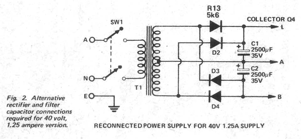
Although the supply was principally made for 20 volts at 2.5 amps it ended up being recommended that the exact same supply may be accustomed to supply 40 volts at 1.25 amps and that this may be of more appropriate to many end users.
This could be accomplished by modifying the settings of the rectifier and by altering a few components. Some idea was handed to creating the supply switchable however the additional complexities and price were in a way that it was disregarded to be advantageous.
Therefore you need to basically choose configuration that matches your demand and build the supply as necessary.
The maximum regulated voltage accessible is restricted possibly by the input voltage to the regulator being too reduced (with more than 18 volts and 2.5 amps) or perhaps from the ratio of R14/R15 and by the value of the reference voltage. (Output = R14+R15/R15 )V ref
Because of the tolerance of ZD1 the complete 20 volts (or 40 volts) is probably not accessible. If it is identified like a situation R14 must be increased to the subsequent favored value.
Single turn potentiometers have been given for the voltage and current controls due to the fact that they are affordable. Nevertheless if accurate setability of voltage or current control is needed ten-turn potentiometers ought to be applied as a substitute.
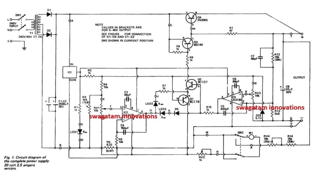
HOW IT WORKS
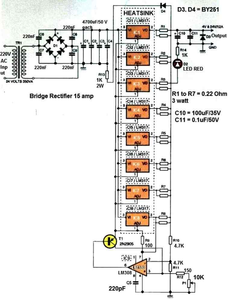
The 240 volt mains is stepped-down to 40 Vac through the transformer and, based on which supply has been developed, rectified to either 25 or 5 Vdc.
This voltage is actually moderate since the actual voltage will be different between 29 volts (58 volts) on no-load to 21 volts (42 volts) on full load.
The identical filter capacitors are employed in both situation. These are attached in parallel for your 25 volt variant (5000uF) and in series intended for the 50 volt model (1250uF). ln the 50 volt model the centre tap of the transformer will be coupled to the centre tap of the capacitors hence guaranteeing accurate voltage. sharing amongst the capacitors. This set up additionally offers a 25 volt supply to the regulator lC.
The voltage regulator is essentially a series type in which the impedance of the series transistor is governed in such a method that this voltage throughout the load is kept constant at the predetermined value.
The transistor Q4 dissipates a great deal of power particularly at low output voltages and high current and it is hence installed on the heatsink within the backside of the product.
Transistor Q3 brings current gain to Q4,the collaboration performing like a high-power, high-gain, PNP transistor. The 25 volts is decreased to 12 volts through the integrated-circuit regulator ICI. This voltage is commonly employed as the supply voltage for the CA3130 lCs and it is additionally lowered to 5.1 volts by zener diode ZDI to use as the reference voltage.
The voltage regulation is conducted by lC3 that examines the voltage as determined by RV3 (O to 5.1" volts) with the output voltage as divided by R14 and R15. The divider provides a division of 4.2 (O to 21 volts) or eight (0 to 40 volts).
On the other hand in the high end the obtainable voltage is restricted to the point that the regulator manages to lose control at high current as the voltage through the filter capacitor reaches the output voltage plus some 100 Hz ripple may also be found. The output of IC3 regulates transistor Q2 that subsequently controls the output transistor in a way that the output voltage continues to be consistent irrespective of line and load disparities. The 5.1 volt reference is offered to the emitter of Q2 through Q1.
This transistor is actually a buffer stage to counteract the 5.1 volt line from becoming loaded. Current control is conducted by IC2 that analyzes the voltage determined by -RV1 (O to 0.55 volts) using the voltage created around R7 by the load current.
If say 0.25 volts is defined on RV1 and the current taken from the supply is small, the output of IC2 is going to be near 12 volts. This leads to LED 2 being lit up since the emitter of Q1 is at 5.7 volts.
This LED consequently signifies that this supply is functioning within the voltage regulator mode. lf however the current driven is elevated in a way that the voltage around R7 is little over 0.25 volts (in our illustration) the output of IC2 may drop. Once the output of IC2 drops below around 4 volts Q2 begins switch off through LED 3 and D5. The result of this would be to minimize the output voltage in order that the voltage throughout R7 is unable to surge more.
While this takes place the voltage comparator IC3 attempts to counter for the problem and its output soars to 12 volts. IC2 then consumes more current to make up and this current brings about LED 3 to lumination, implying that the supply is working in the current-limit mode.
To make sure precise regulation the voltage sensing terminals are delivered to the output points Independently from those transporting the load current. The meter includes a one milliamp movement and reads the output voltage (immediately along the output terminals) or current (by ‘measuring the voltage around R7) as chosen from the front panel switch SV2
PCB Layout for the 40V power supply circuit
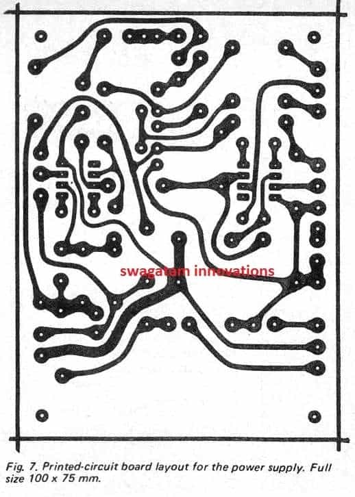
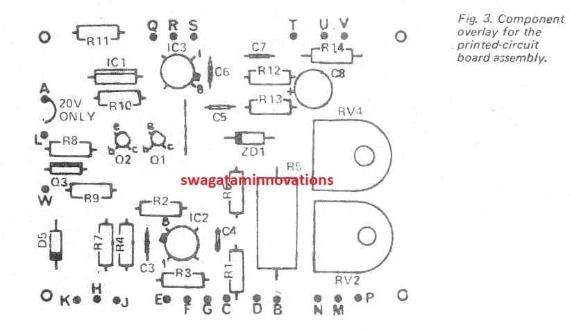
CONSTRUCTION
The suggested PCB layout for this 0-40V variable power supply circuit must be utilized since construction is in so doing tremendously simplified.
The components must be put together onto the board ensuring that the polarities of diodes, transistors, lCs and electrolytics are proper. The BDl40 (Q3) must be installed in a way that the side using the metal surface confronts in the direction of lCl . A small heatsink must be bolted onto the transistor as demonstrated in the picture.
If the metalwork as detailed is used pursuing assembly arrangement must be employed.
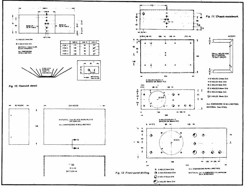
a) Join the front panel into the front of the framework and bolt them with each other by fitting the meter.
b) Fix the output terminals, potentiometers and meter-switch onto the front panel.
c) The cathodes of the LEDs (which we applied) had been designated by a notch within the body that could not possible be noticed while the LEDs were fitted onto the front panel.
If this sounds the situation with yours, reduce the cathode terminals slightly smaller to recognize them after which install the LEDs into place.
d) Solder lengths of wire (around 180 mm long) to the 240 volt terminals of the transformer, insulate the terminals using tape after which attach the transformer into place inside the framework.
f) Mount the mains cord and the cord-clip. wire the power switch, insulate the terminals and after that attach the switch on the front panel.
g) Fix the heatsink and screw it onto the back of the framework by using a couple of bolts - after that install the power transistor utilizing insulation washers and silicon grease.
h) Install the assembled PCB on the framework utilizing 10 mm spacers.
i) Wire the transformer secondary, rectifier diodes and filter capacitors. The diode leads are rigid enough not really to want any extra support.
j) The wiring involving the board and the switches may possibly now come in by hook up points with matching letters in the front panel diagram and component overlay diagrams. The only establishing needed would be to calibrate the meter. Hook up an genuine voltmeter to the output control of the power supply so that the external meter deciphers 1 5 volts (or 30 volts on the alternative set up).
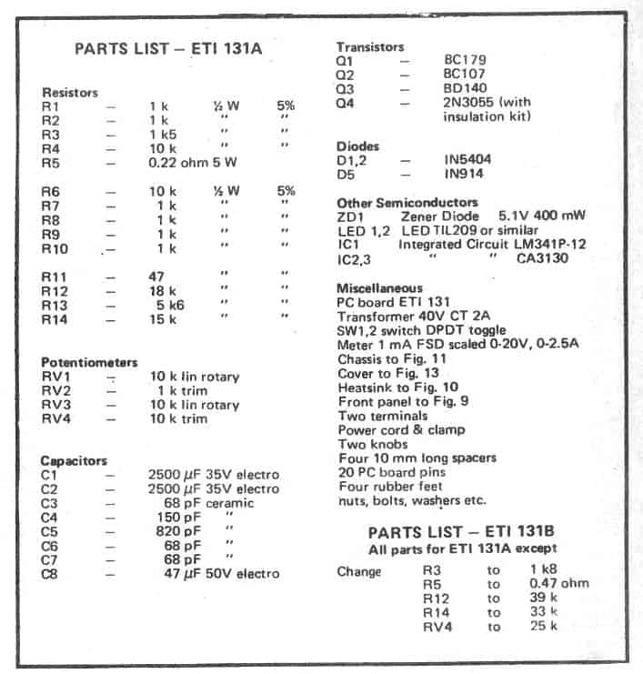
Parts List for the proposed 40V 2 amp power supply circuit


Questions & Answers
hello sir i dont have center tap transformer and i have 0v to 40v transforme can use that your above circuit
Hello Nadir, yes you can use it with a bridge rectifier.
grate information
Great power supply.
From Electronics Today International – July 1976.
Build mine in 1983, and still using it today.
Thanks for your feedback!
Mr. Swagatam:
GREETINGS!!!…..AGAIN!!! You had designed a circuit for me a few years ago and I am truly appreciative of your kind engineering efforts on my behalf. You are truly a very generous and kind person!!!
Now, I am needing a rather hefty power-supply circuit. It appears as though your “0-40V Adjustable Power Supply Circuit” is in the right direction of what I am looking for, but my application needs a bit more than what this circuit is capable of. Here are my requirements:
I am looking to build a “Bench-Top Power-Supply” that is capable of delivering an adjustable and also a Dual-Voltage ( +30VDC / -30VDC ) output controlled by a single potentiometer (i.e. “tracking”), with an output current between 8-Amps to 10-Amps. I already have a small box filled with miniature voltage and current meters, so I can use them to display the set voltage output and the amount of current being drawn by the various circuits. Additionally, the power-supply circuitry should have some means of built-in “short-circuit protection”, to protect the power-supply should the output leads ever become shorted.
The mains transformer would be for the U.S. at 120VAC and capable of providing the 8-to-10 Amps of output current.
There should be a “Current Output” potentiometer to set a “current limit” for each circuit that is being powered by this power-supply and is undergoing development and testing. Maybe there could be a flashing LED that would give a visual warning that a circuit is drawing more current than what the “Current Limit” setting potentiometer is set at. Is that possible?
I will take care of both the mechanical design of an enclosure and the layout of the PCB’s, but perhaps you could provide some suggestions for the heatsinks necessary of the output current transistors?
As an afterthought…..perhaps it would also be nice to have a “secondary” fixed output voltage of either 5VDC or 12VDC to separately power a set of Arduino or Raspberry Pi circuit boards, while the main output of this power-supply is powering all of the development and peripheral circuitry. Let me know if doing this easily is possible, OK? THANKS!!!
And, finally…..I also very much welcome any of your own ideas and suggestions that could be included into the design of this benchtop power-supply. I would like to hear what any of your ideas would be!!!
I am highly looking forward to hearing back from you shortly with your comments and schematic diagram of the design of this benchtop power-supply design. I believe that you are an exquisite design engineer!!!
Regards,
Jerry B. Williams
Senior Electronics Mechanical Packaging Designer
/
Mr. Swagatam:
“THANK YOU!!” so very much for your assistance in helping with a high-current power-supply design!!!
I am about to order the toroid transformers for both the “Adjustable 0 – 50VDC @ 10A” circuit and for the “0 – 40VDC @ 5A” voltage-switchable circuit. Since I will be building 2-each of these power-supply circuits I will then need a total of 4-transformers which cost me USD $200.00. WOW!!!
In any case, while reviewing the “Adjustable 0 – 50VDC @ 10A” schematic that you have provided, I have noticed some errors in the schematic and I also need a couple of items clarified for me about this schematic diagram. Here they are:
1) Will a transformer rated at 48VCT ( 2X 24VDC ) be correct to use for this circuit? The transformer I am thinking of using has a current rating of up to 16A. Should this type of transformer NOT be correct, could you please provide me with the transformer secondary output specifications, so I may be able to select the correct type of transformers for this project? THANKS!!!
2) D1 – D4 are called out as being “6A4” types, which I have never heard of. However, I am assuming that a diode bridge rectifier rated at 1,000V @ 25A should be more than sufficient, correct?
3) P1 – P4 are specified as being 2.5K (i.e. 2K5) Ohms in value. Could you somehow change the circuitry so 5K Ohm potentiometers could be used instead? All of the suppliers show every value of pot – EXCEPT – for the value of 2.5K and the 2.5K pots that they do have are all very expensive!!! But, I can buy 5K pots for $0.80 to $1.50 each!!! Is this possible?
4) The diode shown being connected to both of the P2 potentiometers is shown as being “D1”. Shouldn’t this diode be shown as being “D5”?
5) While doing my parts searching for both the 2N6284 and 2N6286 transistors, several of the online parts suppliers had notes on these 2 parts showing that these parts are on an “Obsolete” list!!! Is it possible for you to specify some more modern and/or recent transistors, perhaps in a TO-220 style, for this circuit function? I have a small box-full of TO-220 20-Watt heat-sinks that I could use to mount these transistors to onto a PCB.
I have also already ordered several small digital DC-voltage and DC-current LED meters to show what is going on, on my chassis front-panel. I have also already ordered most all of the standard capacitors, resistors, power-inlet modules, LED’s and other hardware items for my building 2 of these power-supply chassis (one for me to use and the other for a younger family relative member).
I also have some questions concerning the “3V/5V/6V/9V/12V/15V” schematic, but I will first wait until I am able to receive your answers concerning my “0 – 50V @ 10A” schematic questions. And, while I feel that all of my questions are important, my most important questions are those concerning about TR1 and P1 – P4. I do not wish to spend $200 on possibly the wrong type of transformers, so your answers are vitally important!!! THANK YOU!!!
And, finally…..if you could provide me with your personal e-mail address, I would like to financially compensate you for your kind assistance through PayPal. I truly value – ALL – of your engineering design expertise and I would like to help you for helping me. Is this possible? THANKS!!!
Regards,
Jerry B. Williams
/
Hello mr.Swagatam,
i’m a newbie in pcb design( just a hobbist).And i want to build this 40v power supply .My question is what the type of trace/track like that(worm)?? Thankyou
Susilo:
Somehow your question was also forwarded to me, JBW. I see that Mr. Swagatam has also answered you.
In the future, please only contact Mr. Swagatam with your questions, as my e-mail address inbox already receives more than enough messages from people in the forums I subscribe to. THANK YOU!!!
JBW
/
Mr. JBW,
Sorry for the trouble, actually the readers sometimes accidentally press the REPLY button under an existing comment causing an email notification to be sent to the original commenter also. Unfortunately this cannot be prevented or prohibited in this commenting platform.
If this happens again, you can feel free to block the emails.
Hi Susilo,
Sorry i did not understand your question. Where is the worm like track that you are referring to?
Mr.Swagatam,i mean the pcb trace like mitre or curve.I see in your pcb layout of 0-40v adjustable power supply.Thx
Thanks Jerry,
Here are the answers:
1) 48V (60V after rectification) 16 amp is OK for this circuit, but T1 might need to be replaced with a TIP35 transistor on heatsink.
2) 1000 V 25 amp diode will be fine.
3) 5K pot will although it may change the calibration scale, which might correspond with R4 value. Base resistor of T3 can be removed.
4) D1 is mistakenly shown as D1, should have been D5
5) You ca try two TIP35 as Darlington, or 2N2222 and TIP35 as Darlingtons.
Wish you all the best…sorry I do not except any kind of compensation for this, although I appreciate your thoughts very much.
Mr. Swagatam:
(I had tried to contact you by using your “wordpress@162.240.8.81” address, but I am uncertain if my message was actually sent out and received at that address. So, I am re-sending my message to you “the old-fashioned way” by using a “Reply” on your website).
In regards to your your recent reply back to me, I now have the following inquiries and questions:
1) If the 48VCT of the power transformer is OK, what would be the – minimum – VCT or possibly an “ideal” VCT of a power transformer to operate this circuit. I ask you this question because the cost of this power transformer is dependent upon the “VA” rating of the transformer. Therefore, the cost of a transformer at 48VCT @ 10A will be more than a transformer specified as 36VCT @ 10A, assuming that the 36VCT transformer is acceptable. In other words, what would the – minimum – VCT be for a transformer to still properly operate this circuit? I am attaching a datasheet of a possible transformer I wish to purchase.
2) You had mentioned creating a new Darlington-pair using a TIP35C and a 2N2222 transistor. Therefore, I am now assuming that the complement to this Darlington-pair would then be a TIP36C and a 2N2907 transistor, is this correct? In your response, you made no mention of what the complementary pair of transistors should be and I am just assuming that the above is correct. Can you verify this for me please? THANK YOU!!!
3) Just a few minutes ago I placed an order with an electronics parts distributor for several 5K potentiometers (@ $0.50 each, versus $5.00 to $8.00 each for the 2.5K potentiometers). However, I had selected “dual-potentiometers) instead of “single” pots, because I wish to have both the Negative and Positive voltages and currents adjusted at the same time, instead of everything being individually adjusted. However, based upon your reply to my question about changing the value of these potentiometers, could you provide me with the corrected or updated resistor values around these potentiometers? Also, based on nominal values of normal voltages and current outputs, could you provide me with a value for the R4? I would greatly appreciate it very much. And, finally…..would the circuit operate in the same manner if I placed a 5K resistor in parallel with the potentiometers, effectively creating a 2.5K pot? Let me know if this would work properly. THANKS!!!
4) By increasing the value of the potentiometers to 5K, why can the “base resistor” going to T3 be eliminated? Shouldn’t there be at least some nominal value of a resistor still be placed there? And, why does the resistor that is connected between P1 and T3 does NOT have a “Reference Designator” (R?)? By not having a “Reference Designator” does this mean that this resistor is “optional”?
Again…..I cannot “THANK YOU!!” enough for all of your design engineering assistance!!! And, by your refusing to accept my offer of wishing to financially compensate you for all of your kind assistance, it speaks volumes of your generous character and of your willingness to so freely and openly help others like myself in our various design engineering projects!!! You are truly a very kind and an exceptional person!!! I personally and sincerely wish you all of the best in all that you do!!! I just wish that I could do something for you in return.
Did you ever install, load-in and use the FREE schematic capture program that I had given to you so long ago? If not, that schematic capture program would have made the design of all of your schematics so much easier and it would have also allowed you to model your schematics using PSpice. Maybe one day you could look into it. That particular schematic capture program was developed by one of the largest CAD-design program developers in the CAD world!!!
I am looking forward to receiving your new reply, which will then allow me to finally order the transformers for this power-supply project. THANKS!!!
Regards,
Jerry B. Williams
/
Thanks Jerry,
I think this comment should have been posted under the following link:
https://www.homemade-circuits.com/0-to-50v-0-to10amp-variable-dual-power/
No problem, here are the answers:
1) This circuit can be operated even with voltages as low as 5V, so 36V is fine!
2) Yes the mentioned PNP complementary pair is correct.
3) R4, will depend on the maximum current limit you wish to have at the output, such that it develop around 2V across itself, and the pot P1 must be selected such that the 2V is uniformly calibrated across the pots scale.
4) The base ersistor is not related to the pot value, I advised to remove because the T3 is already protected by R5 so the base can be ignored.
I appreciate all your feedback!
Let me if you have more questions, I’ll be happy to help!
Thanks Jerry,
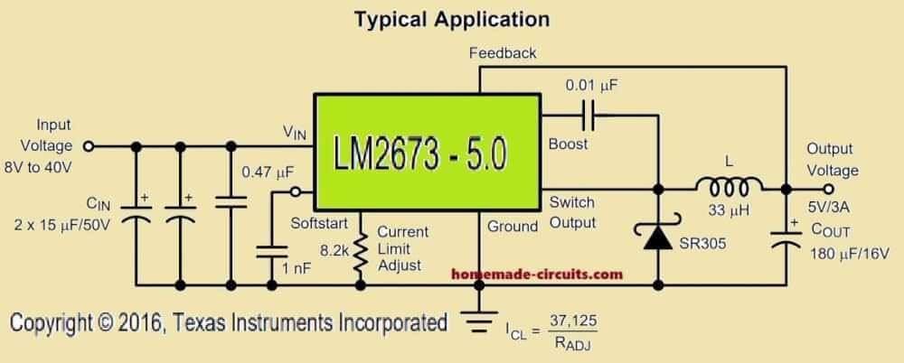
I think using ready made linear ICs to make a power would produce better results than using discrete parts. Here’s one link that you may try:
https://www.homemade-circuits.com/dual-power-supply-3v5v6v9v1215v-with/
For booting you could add external bypass transistor for the ICs.
Dear Mr. swagatam,
Accidentally i saw your web site & is highly remarkable.
I am a retired Automobile engineer with a flair for Electronics. At present i am in U.S, . I spend the time in helping Non profit organisation, by rectifying / repairing laptops, mobiles etc,
Even though i have seen many options in DIY Variable bench power supply, i thought you may be the right to approach.
I got a DELL 19.5V 6.7A power adapter & i want to use this for making variable power supply.
Could you pl suggest the best option to build one, with your circuit & List of materials.
thank you,
a.v.krishnamoorthy
Thank you Dear A.V.krishna moorthy,
All SMPS systems have an opto-coupler based feedback system for regulating the output voltage level to a predetermined fixed level. It is possible to tweak the adjustments around this opto coupler for getting a range of different voltages at the output. The change can be probably in the form of a potentiometer replaced for a resistor around the opto-coupler.
I have provided all the details in the following post, which you an efer:
https://www.homemade-circuits.com/how-to-make-variable-current-smps/
you’re right.i forgot to calculate wattage.thank you for help and formula.keep helping. i built my first dual power supply from studying your dual power supply concept.i am planning to build little by little power supply,stabilized,precised,and much more efficient.you’re a BIG HEP!
thanks Dennis, You are most welcome?
hi swag.
i built a power supply and i used LED and 12k resistor as mains ac indicator.my LED got busted.how to calculate led’s resistor from any ac source like 220,110 vac.thnx
Hi Dennis, Your resistor value is correct, but wattage may be wrong….you can do it through simple Ohm’s law, as given below:
R = V/I = 220V / 0.02(LED Current) = 11000 ohms or 11K
wattage = R x I^2 = 11000 x (0.02)^2 = 4.4 watts, or simply 5 watt….but this will still dissipate a lot of heat, so better to go with a 10 watt resistor
Don’t forget — 220 V is the RMS voltage. Within one cycle the voltage actually varies between +/- 156 V.
For half the cycle the diode is reverse biased, and cannot handle such a large reverse voltage.
During the peak forward portion of the cycle, your LED will flow more than 20 mA in each cycle. Example 20 mA x sqrt(2) = 28 mA peak.
LEDs are not suitable as mains indicators. Anyone considering this application might consider a neon panel lamp.
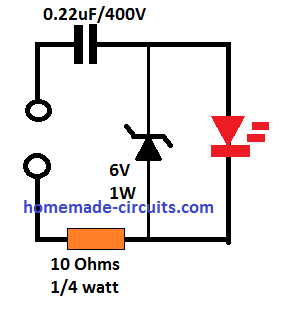
In that case we can rectify the mains with a bridge rectifier and use 310V in the Ohms law, this will solve the issue of any damage to the LED. Or to be even safer use a capacitive supply such as this:
Neon can be used but mostly it is difficult to find good quality neons, and the bad ones don’t last long or produce inconsistent illumination
do have a dc kv range power supply here? like 20kv-30kv 500uA?
you can try the following concept
https://www.homemade-circuits.com/make-this-ultra-violet-uv-water-filter/
sir if i have two rectified dc power supply from same tranformer 12 0 12
Q1 can i connect dc output of these transformer in parallel
Q2 wht happen if dc outputs of two different trafo connected in parallel ?
you can connect their output in parallel, just make sure the center tap has two wires, in total 4 wires should be there, connect two wires with one bridge, the other wires with another bridge and then you can connect the output from the bridge in parallel.
no no sir i did spelling mistake in my previous comment.
i means to say i have two transformer of same rating.both trafo have 12 0 12 tapping.
basically i want to make uninterrupted dc power supply bcoz i have two ac power source if ones then their will another give supply.
OK, still you can connect their outputs in parallel after the bridge.
I am not able to interpret this circuit, how will the cells get charged? there's no negative supply outlet for the cells, neither is there any positive input??
I have not yet investigated a passive circuit for this but this can be done through a relay based circuit as shown below, although it looks a bit lengthy:
https://www.homemade-circuits.com/2015/08/lipo-battery-balance-charger-circuit.html
by the way do you want to balance across parallel cells or series cells??
Hello,
Please feel free to ask the questions here, I'll try my best to solve them…