In this post I have explained a simple lithium polymer (Lipo )battery with over charge cut off feature. The idea was requested by Mr. Arun Prashan.
Charging a Single Lipo Cell with CC and CV
I came across your work on “Bicycle Dynamo Battery Charger Circuit” in Homemade circuit design blog. It was really informative.
I would like to ask something regarding that article. I am working on a hexapedal robot with battery switching mechanism. Once the primary battery gets beyond a preset voltage, secondary battery will power up the robot’s system. My concern is not regarding the switching circuit.
Together with this, I am working on energy generation by attaching a generator to each motor. The current generated is intended to be used to recharge 30C 11.1V 2200mAh 3 cell LiPo battery.
I am aware that the circuit mentioned in “Bicycle Dynamo Battery Charger Circuit” will not be useful for my purpose. Can you give me any other option pertaining my issue. I just need to know on how to modify the circuit to make it LiPo compatible with constant voltage and constant current or CC and CV rates. Thanks, looking forward for a reply.
Regards,
Arun Prashan
Malaysia
The Design
A Lithium polymer battery or simply a lipo battery is an advanced breed of the more popular lithium ion battery, and just like it's older counterpart is specified with stringent charging and discharging parameters.
However if look at the these specifications in detail we find it to be rather lenient as far as the rates are concerned, to be more precise a Lipo battery can be charged at the rate of 5C and discharged even at much higher rates, here "C" is the AH rating of the battery.
The above specs actually gives us the liberty of using much higher current inputs without worrying about an over current situation for the battery, which is normally the case when lead acid batteries are involved.
It means the amp rating of the input could be ignored in most cases since the rating may not exceed the 5 x AH spec of the battery, in most cases. Having said that, it's always a better and a safe idea to charge such critical devices with a rate that may be lower than the max specified level, a C x 1 could be the taken as the optimum and the safest rate of charging.
Since here we are interested in designing a lithium polymer (Lipo) battery charger circuit, we'll concentrate more on this and see how a lipo battery may be charged safely yet optimally using components that might be already sitting in your electronic junk box.
Referring to the shown Lipo battery charger circuit diagram, the entire design could be seen configured around the IC LM317 which is basically a versatile voltage regulator chip and has all the protection features built in. It will not allow more than 1.5 amps across it's outputs and ensures a safe amp level for the battery.
The IC here is basically used for setting up the exact required charging voltage level for the lipo battery. This may be accomplished by adjusting the accompanied 10k pot or a preset.
Circuit Diagram
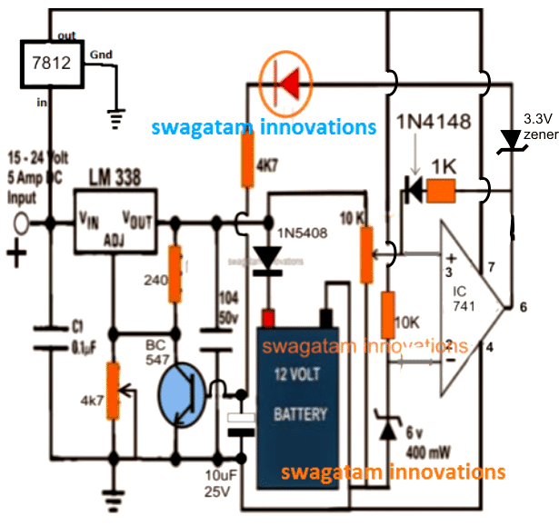
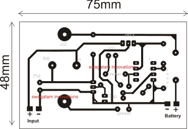
The section at the extreme right which incorporates an opamp is the over charge cut off stage and makes sure that the battery is never allowed to overcharge, and cuts off the supply to the battery as soon as the over charge threshold is reached.
Circuit Operation
The 10 k preset positioned at pin3 of the opamp is used for setting the over charge level, for a 3.7 V li-polymer battery this may be set such that the output of the opamp goes high as soon as the battery is charged to 4.2 V (for a single cell). Since a diode is positioned at the positive of the battery, the LM 317 output must be set to about 4.2 + 0.6 = 4.8 V (for a single cell) for compensating the accompanied diode forward voltage drop. For 3 cells in series, this value will need to be adjusted to 4.2 x 3 + 0.6 = 13.2 V
When power is first switched ON (this must be done after connecting the battery across the shown position), the battery being in a discharged state pulls the supply from the LM317 to the existing level of its voltage level, let's assume it to be 3.6 V.
The above situation keeps pin3 of the opamp well below the reference voltage level fixed at pin2 of the IC , creating a low logic at pin6 or the output of the IC.
Now as the battery begins accumulating charge its voltage level starts rising until it reaches the 4.2 V mark which pulls pin3 potential of the opamp just above pin2 forcing the IC's output to go instantly high or at the supply level.
The above prompts the indicator LED to light up switch ON the BC547 transistor connected across the ADJ pin pf the LM 317.
Once this happens the ADJ pin of the LM 317 gets grounded forcing it to shut off its output supply to the lipo battery.
However at this point the entire circuit gets latched in this cut off position due to the feedback voltage to pin3 of the opamp via the 1K resistor. This operation makes sure that the battery under no circumstance is allowed to receive the charging voltage once the over charge limit is reached.
The situation stays locked until the system is switched OFF and reset for possibly initiating a new charging cycle.
Adding a Constant Current CC
In the above design we can see a constant voltage control facility using LM338 IC, however a constant current seems to be missing here. In order to enable a CC in this circuit, a small tweak might be enough to get this feature included, as shown in the following figure.
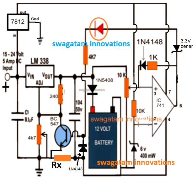
As can be seen, a simple addition of a current limiting resistor and a diode link transforms the design into an effective CC or constant current Lipo cell charger. Now when the output tries to draw current above the specified CC limit, a calculated potential is developed across Rx, which passes through the 1N4148 diode triggering the BC547 base, which in turn conducts and grounds the ADJ pin of the IC LM338, forcing the IC to switch OFF the supply to charger.
Rx may be calculated with the following formula:
Rx = Forward voltage limit of BC547 and 1N41448 / Max battery current limit
Therefore Rx = 0.6 + 0.6 / Max battery current limit
Lipo Battery with 3 Series Cells
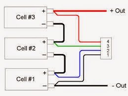
In the above proposed 11.1V battery pack, there are 3 cells in series and the battery poles are terminated separately through a connector.
It's recommended to charge the individual batteries separately by locating the poles correctly from the connector. The diagram shows the basic wiring details of the cells with the connector:
UPDATE: In order to achieve a continuous automatic charging of a multi-cell Lipo battery, you may refer to the following article, which may be used for charging all types of Lipo batteries regardless of the number of cells included in it. The circuit is designed to monitor and automatically transfer the charging voltage to the cells which might be discharged and needs to be charged:


Questions & Answers
Hi Mr.Swagatam,
I went through “Lithium Polymer Battery Charger Circuit” as I request few days back. Impressive explanation. But I have a question, turns out to be rather a silly one. The LiPo battery I have has a separate charging pins. It has 4 pins in total. What are the modifications required for that particular battery. Together I’ve attached the power terminal and charging terminal of my battery.
Thank you.
Hi Arun thank you, I have the updated the required info in the above article, please check it out…you may have to charge the cells individually using the above charger circuit after locating the poles correctly inside the connector.
Appreciate it, thank you.
Is the component in the circled region is a potentiometer? If not how shall I modify it?
https://drive.google.com/file/d/0B3p3Sae8pVavTzZFR0Rfc3NTNzg/edit?usp=sharing
it should be a preset ideally, because we want to set it only once.
Adjust the voltage at the output of LM317 to 4.8V (without any battery connected) now set the opamp 10k preset such that the LED just comes ON.
In the above process connect the LED 4k7 resistor to ground and NOT with the base of the BC547….once the setting is complete you may restore the position to the base of the BC547.
Now your circuit is ready and can be used for the intended results.
while doing the above also make sure that the 1K feedback from the opamp pin6 is kept disconnected…restore it back to its indicated state after the setting-up procedure is completed.
I did the above setup and adjusted the output of LM317 to 4.8V without Lipo battery connected. What I found weird is that the LED light up once I connect the circuit with external supply (dynamo/24V lead acid battery-4A). Where did I go wrong? I tried the setup again and noticed that the LM317's output is 1.2V no matter how I tune the potentiometer.
you surely did not do the way I suggested in the above comments.
I told you to disconnect the LED 4k7 from the transistor base and connect it to ground, and also to keep the 1K across pin6 and (+) of the opamp disconnected during the setting up procedure….after this you will need to adjust the preset carefully until the LED just shuts off…seal of the preset in this position and restore the 4k7 and 1k to their original positions.
correction
…adjust the preset until the LED just lights up….
Im using LM741 now. I'll tell you how I connected and correct me if I'm wrong.
2: -Vin (10K and 1K feedback resistor to 3V zener)
3: +Vin (from 6V zener and 10K resistor)
4: -Vcc (GND)
6: Output (to cathode of 3V zener)
7: +Vcc (power terminal before 0.1 uF capacitor)
I am sure my mistake is somewhere in these connections.
I think there could be many mistakes in your circuit, a clear diagram is in front of you so there shouldn't be any chance of a mistake.
Please click the diagram to enlarge it and do it exactly as shown
For IC 741:
(+)input is pin3
(-)input is pin2
(+)supply is pin7
(-) supply is pin4
pin6 is the output
After you finish correcting your circuit adjust the persets as explained previously…I have already the setting up procedure, please you'll follow it carefully for getting the correct ersults.
Hi Mr Swagatam, sorry for disturbing you everyday. I was checking on an appropriate generator coupled with a high torque DC motor. Then I checked that the above diagram where it states 15-24V 5A input. 5A rated generator seems to be hard to get. Can you advice on the minimum current needed to run the charging circuit or am I left with using a current booster circuit?
Hi Mr. Arun, the input amp rating should be according to the Lipo battery rating, in your case since the cells are rated at 2200mAH, a 2 to 3amp input could be used, the diagram was taken from some other application in this blog so the 5 amp was mistakenly printed, is not crucial and may be replaced as per the present situation.
Hi, I've started to construct the above circuit and I would like to clarify one condition. 3V zener diode after the output of LM324 is in reverse polarity. Does this indicate the diode's breakdown/knee voltage? Correct me if I'm wrong. Thanks.
Yes the zener is positioned so that it conducts only when the output of the opamp has crossed the knee voltage of the zener, ensuring a legitimate full charge signal from the opamp
So I am free to choose the op amp 324 inputs?
Pin 2&3 or 5&6?
The negative feedback will be in either pin 2 or 6, I am correct?
yes, but the unused opamps must be used as "followers" with the one that's used for the above application for ensuring stability of the IC.
Alternatively you can use a single opamp such as a 741
I would like to try with LM324. Correct me if I'm wrong, the negative input will be after 1K feedback resistor while the positive input will be from 10K resistor. In the diagram its shown the other way.
In terms of 741, how would the pin connections differ?
2= -Vin
3= +Vin
4= -Vcc (ground?)
6= o/p (to 3V zener)
7= Vcc (positive)
Am I correct with the flow?
sorry i did not understand your first question….
the 741 pinouts are correct and can be used in the above circuit
Hi Swagatam!
Pls guide me connect to LM324 ( as me known LM324 has 14 pin). I have 02 cells Li-Ion Battery(ICR-18650-28A) I can use The circuit for charge it. How many Current of above circuit is ?
Hi Linh,
you can use a 741 IC or a LM321 IC instead of the LM324…
yes you can your charge your cells separately using the above design, the current will depend on the selected input source current specs
Many Thanks SWAGATAM.
Pls sir,I need 12v 200ah battery over charge cut off
iyiola, you can try the following circuit:
https://www.homemade-circuits.com/2011/12/high-current-10-to-20-amp-automatic.html
..
can i use this circuit for batre 3,7V with current 40A?
sure, just replace LM317 with a LM338 or LM396
can i use this circuit to 12 volt 9.8 amp lipo battery?
and from 12volt solar panel?
thank you…
can i use this circuit for 12 volt 9.8 amp lipo battery and from solar panle?
thank you…
yes you can by just replacing the LM317 with a LM196 IC……….use sufficiently large heatsink with it.
Hi Swagatam
I'm using 2S 7.4V battery.. which has 3 balance wires, how should i connect those wires?
Hi Omar, the above charger circuit does not have a balance input feature, therefore you may have to trace out the individual wires of the cells and charge them separately using the above charger.
Hi Swagatam
Need your help want to make 5S lipo battery charger, can I make above circuit 5 same block and charge it through balance connector of battery, one more problem is 3V & 6V zenar are not available in kolkata market can i use 3.3V & 6.2V zenar and then the modification to circuit is needed.
will you help me
Protik Banerje
Hi Protik,
yes you can 5 of the above explained circuit modules and charge your 5S cells individually.
the zener value is not critical, it just needs to be lower than the charge voltage… you can use any value that may be approximately 50% lower than the charging voltage
sure I'll guide you through…feel free to ask anytime…
Thanks for your guide.
I will start constraction on vero board and get in touch with you.
Thanks
once again>>>>>>>>>>>>>>>>>>>>>>>>>>>>
HI Swagatam
I have 3200mAH 5S 35C Lithium Polymer Battery that will work perfectly OK.
Hi Protik,
Yes it can be charged without issues.
By the way I'll be quite soon publishing an article which will include a specialized Lipo automatic battery charger circuit using a scanning method.
HI Swagatam
Please let me know how soon will it published.
thanks to infroming me I will wait for it also.
Hi Protik,
you can find it here:
https://www.homemade-circuits.com/2015/08/lipo-battery-balance-charger-circuit.html
HI Swagatam
Sorry in advance to disturb you everyday.
How long it will take to charge 3200mAH 5S 35C Lithium Polymer Battery and if I need to charge it little fast what what to do.
Hi Protik,
please feel free to comment as much as you want….you can select a 5 amp charging input in order to ensure a relatively quick charging of the cells.
HI Swagatam
Need one more help, This time I need Brushless motor ESC with BEC for my Aquastar 3974-2200KV 18.5V.
I bought the motor from Hobbyking along with ESC 120A but the ESC is giving trouble so I have return it they will give me the replacement with two months. I need one home made ESC backup for my 32" Catamaran boat.
Hi Protik,
you can try the following circuit:
https://www.homemade-circuits.com/2015/06/pwm-motor-soft-start-circuit.html
just replace R9 with a 1K pot
HI Swagatam
I made the circuit but the problem is, it took 24hours to charge only 1S and balance are same,
But the 1S volt was 4.28V on my fluke meter and the red LED didnt glow.
I know the wiring for five boards was wrong, could you please draw me a line diagram how to connect all five boards and to my 5s lipo balance connector'
Thanks
waiting for the reply.
Protik
One think more, are you bong.
Hi Protik,
How did you connect the charger with the cells? I am sorry, just forgot to tell you that only one charger circuit needs to be built and connected with the individual cells separately one after the other, 5 chargers won't suit the application since the cells are in series.
yes I am bong 🙂
Kemon acho Swagatam.
Once again came to disturb you
Now i need help for my house over head water.
I want to make a circuit which will tell me the water level and when i start my pump as soon the tank get full it should be Auto off.
Can you help Boss.
Thanks
Protik
Ami bhalo aachhi Protik, thanks
for the automatic cut off, you can try the following circuit:
https://www.homemade-circuits.com/2012/04/cheap-semi-automatic-tank-water-over.html
and for the indication purpose you can try this:
https://www.homemade-circuits.com/2012/04/make-this-water-level-indicator-circuit.html
Hi Swagatham
Now I am a regular reader of your blog. I appreciate you.
Most of your battery charging circuits include a lm741 op amp ic. Can I use a half part of lm358 in place of lm741….? I am aware about pin configuration of lm358. I just want to know about, do I need to change the resistor values when I use lm358.
Thanks in advance.
Thanks Anil,
You can use any opamp of your choice for the mentioned application without changing anything, however using single opamp versions would be more suitable and reliable because for multiple opamp ICs, the unused opamp could become unstable unless the pinouts are configured appropriately.
LM321 cold be the most appropriate one.