In this article I have explained a VLF receiver circuit used for detecting insect wing beat signals, the idea was investigated and built by Mr. Steven Chiverton.
Insect Wing Triggered ELF
An incredibly fascinating electrical outcome successfully identified with the VLF are wing sounds triggered when bugs like bees, flies, and mosquitoes fly within a few feet of the VLF whip antenna.
The ensuing signal is a buzzing noise nearly the same as what may be listened to by ear, in spite of this, this impact is brought on by electrostatic releases every time the insect's wings flap.
It can be considered that electrostatic charges (static electricity) are amassed on the insect's wings then simply thrown out through each wing whip, producing a "modulated" electrical field around the pest at the identical frequency as the wings whisk.
Big insects, along the lines of wasps, Yellow jackets, Bumblebees and honeybees, render notably powerful buzzing sounds in the headphones-easily heard once those insect fly within 4 feet (1 meter) of the VLF antenna.
Mosquito Wing Beats
High-pitched Mosquito wing beat noises is generally noticed the smaller bugs within a couple of inches of the VLF Receiver's whip antenna.
Particular types of flies as well as other pesky insects possess considerably more electrostatic "buzz" out of them compared to other forms - Bees and Horse Flies, in our findings, include the loudest "buzz" in the earphones!
This might likewise have something connected with the structure of the insect's wing, with specific form of bug wings higher susceptible to static electricity build up and ensuing discharge.
There could be insect physical electrical releases produced within the insect's wing muscle tissues that help cause this , although not much is recognized concerning this occurrence.
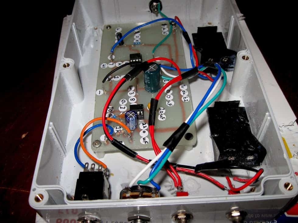
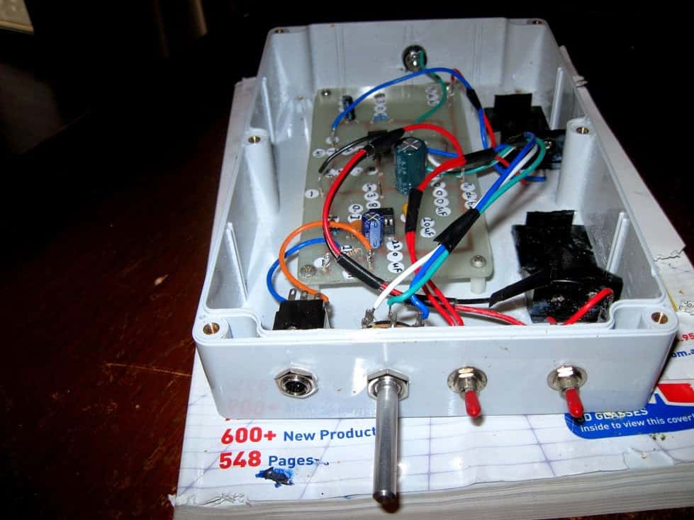
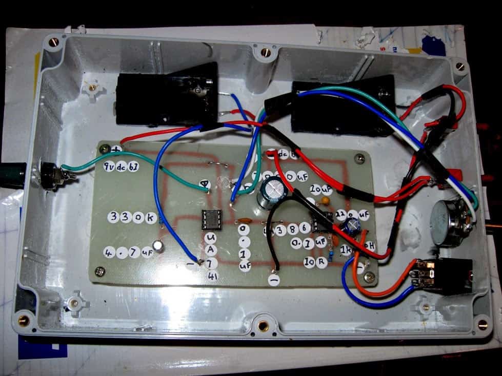
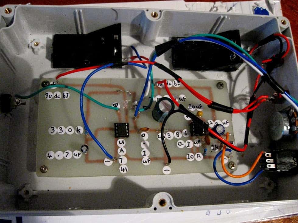
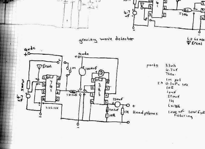
I've listened to sound recordings like whistlers etc and not one of these sounds matches the recordings I've collected from what I've received on my gravity wave detectors,
Detecting UFO Sounds
I'm working on 2 new VLF receiver circuits to receive these mystery VLF signals whether they be UFOs , there’s no info on these signals and there relation to UFOs if there’s one,
But I recall stories of people who hear low humming noises coming from UFOs , it’s a very low frequency signal itself and maybe if it uses ac it also covers, the VLF band of frequencies to, anyhow the iron peaces I need to make the core to concentrate the electromagnetic flux has been discontinued at dick smith electronics even though its in there catalog.
But I have enough in my collection to make one flux concentrator for the sensor coil
That fits the closest to the inside circumference of the plastic spool the coil is around.
I'll try jay car electronics to see if they have the same sizes I need for the next planed VLF sensor circuit,
Without the core to concentrate the electromagnetic flux, the signal reception is week but when you put a peace of the core into the centre of the coil the sensitivity jumps more and even more when you sit another core peace on top of the first one
These core peaces can be covered in heat shrink tubing to make it all hold together to form a single looking long core.
I have a number of the pieces so far but they are barrel shaped , so ill have to build the core with all these peaces , and hopefully jay car will have them to so I can construct the second core , for the other circuit to .
If you have read the top bit I to have received buzzing noises from fly’s but with one of my most sensitive gravity wave detectors and it has no areal just a sensor capacitor.
My latest VLF receiver tests have changed when I solder new 9 volts battery snaps into it now it was then more sensitive to the ac mains and recently I made a new lid for the VLF receiver circuit and had to resolder the wires to new leds I put into it now the circuit appears to be less sensitive to the ac hum as its lower as if the circuit is filtering it down or attenuating itself, but it still picks up the ticks from my watch at a good distance.
Using Zero Point Energy
I brought a few DVDs on ebay one called Tesla hunt for zero point energy and the other about Nazi flying saucers how they work something you cant get here so ebay was the place to order them on,
I've brought a number of emf detectors before to, off e bay but one seems to be really good but have got no ufos or ghosts with it and its sensitive but no ghost then to test it on but the one that's the k2 emf detector registers near the fridge here but nothing else that is ac powered gives a reading as if the ghost I saw last night likes to hide inside the fridge hehehehe
Anyhow, I've recently built a new insect gravity wave detector I copied it from my first old design which to my surprise senses insect wing signals from only stripped bodied flies which there isn't any here so far as the whether isn't to good
When I took my old design out and built a neon from it I discovered why it worked so well I mistakenly used pin 8 as the positive input and not pin 7 so I discussed it with Dave dede and he built it and got some bizarre results to and even more as pin 8 is not used on the 741
But Dave found a circuit on the Internet a Chinese one and in the circuit drawing they also used pin 8 for reasons we don't know cant speak Chinese heheh but a little looking around I find pin 8 also has another purpose
I forgot what it is but listed as something else other than just nc so anyhow I fired up my new circuit and even though the only 2 flies that flew by didn't have stripes on them and were to far away to register
Detecting Remote AC Hum
I noticed that the extra sensitivity is very interesting what are they really hiding and why is pin 8 doing things unheard of or not said so I sat outside with the detector on top of an outdoor table and I noticed that when I run my finger on the wooden part of the table the wooden slats that make the top of it I can hear it through my headphones strange
Even more bizarre is the unusual sensitivity to ac fields I bring the detector inside and with my bare feet on the ground
I can hear the ac mains hum but it goes away when I lift my feet off the ground as if the underground power here is absorbed into my body and re radiated so the detector can hear it again now I still have my old insect gravity wave detector design here
I'm using on it and the new one, 2x 9 volts batteries and they are due to be replaced as these nmh rechargeable may have had there days as one keeps loosing power.



Questions & Answers
Sir engineer Swagatam
I am working on a dog repellent circuit using a 40106 IC in conjunction with H-bridge transistors. Currently, the circuit oscillates at a single frequency with a 1000 picofarad capacitor connected between pin 1 and ground, and a 39k ohm resistor connected between pins 1 and 2 of the 40106. I’m interested in achieving variable frequencies for this circuit. Could you please advise on methods to adjust the oscillation frequency? Thank you very much in advance
Moe
Thank you Moe,
However can you please post this question under the following article, it will make your question perfectly relevant wit the article topic.
Once posted I will try my best to solve it for you…
https://www.homemade-circuits.com/dog-barking-preventer-circuit/
Dear Sir Swagatam
Please excuse me for leaving comment here since the reply button is not seen for May 11, 2024.
I trust this letter finds you well.
I have successfully resolved the issue of dropping the voltage to below 12V by applying nine 1.5V batteries instead of eight. When I switched on the circuit, the multimeter showed 11.8V. I then tested the circuit near a friendly cat at the silent park of the morning, at a distance of about 5 meters. Each time I switched on the circuit, the cat would run away and then return to me, may be it was hungry. After repeating this process a few times, I concluded that the circuit is working well. Unfortunately, I did not see a dog, but I am confident that the circuit is powerful enough to deter them as well. Additionally, I tested your proposed circuit and discovered that my piezoelectric is burnt, so I will need to purchase a new one.
I will never forget your kindness and the time you dedicated to helping me solve this problem. I am grateful for your assistance and for all the electronic tips I have learned from you. Thank you, dear Swagatam, for being a true symbol of a kind and generous person.
With warmest regards
Sincerely,
Emad
Please ignore my previous and publish this one.
Thank you so much Dear Emad,
That’s a great progress, I hope it works for dogs also.
Can you please repeat and post this comment under the following article:
https://www.homemade-circuits.com/dog-barking-preventer-circuit/
Because the above article is more relevant to our current discussion.
I have replaced the commenting system to default for better site SEO, therefore there may be some differences in its working. No worries, if you don’t find the reply button, you can always start a new thread.
Also, please note that once you reply it may not be visible in the article immediately, rather will be visible after 3 days, because of server caching…kindly bear with me for this inconvenience. Longer Caching helps my site to load faster.
Hope to hear from you soon…
Dear Sir Swagatam
Hello, I did as per your instruction. You are right Sir that article is more relevant.
I will let you know of my test with dogs also.
Best regards
Emad
No problem, dear Emad.
All the best to you.