In this article we study the microwave sensor IC KMY 24 and try to understand its main features and its pinout implementation details.
How Doppler Sensor KMY24 Works
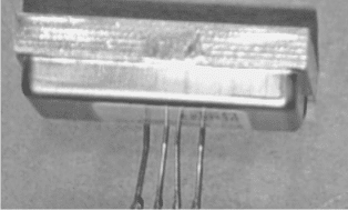
The KMY24 microwave sensor module is designed and built on the concept of Doppler effect. When correctly configured it radiates a low power microwave signal of around 2.45 GHz across the directed zone.
When an object (target) that could be even a human being, comes in the range of the emitted signal, the signals get reflected back to the sensor module with some disturbance relative to the original frequency, this is popularly known as the Doppler shift.
Once this reflected frequency shift is detected by the sensor, the in built circuitry instantly mixes the reflected frequency with the existing original frequency and produces two individual frequencies across its specified outputs.
What's Doppler Effect
As per the principles of Doppler effect this frequency phase shift could be either positive or negative depending upon whether the object in the sensor zone was receding or approaching the sensor.
The function of the KMY24 concludes here, and the outputs from the device now needs to be amplified through suitable voltage amplifier configuration, for example through an differential opamp amplifier circuit etc.
Further on the opamp output may be appropriately terminated with a relay stage or a recorder or an alarm for distinguishing or identifying the sensed parameters.
Technical Features of the IC
The main features of the IC KMY24 may be learned as follows:
- High sensitivity and detection even when a relatively smaller target approaches the zone.
- Twin mixer circuitry for enabling directional movement detection of the target
- High reliability for achieving fool proof results
- Meager power consumption making it perfectly suitable for battery operated applications.
- Minimal harmonic emission for reduced RF disturbance in the atmosphere.
- Compact size.
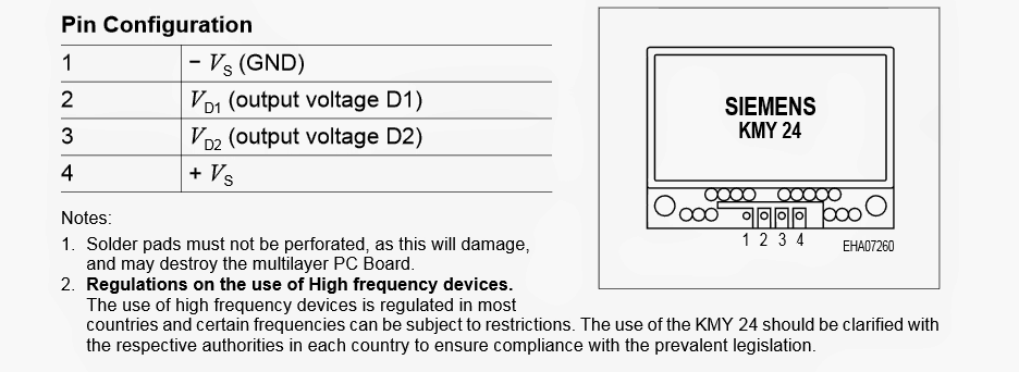
The following image shows the pinout details of the KMY 24 microwave sensor
Pinout Detail of the Microwave Sensor IC
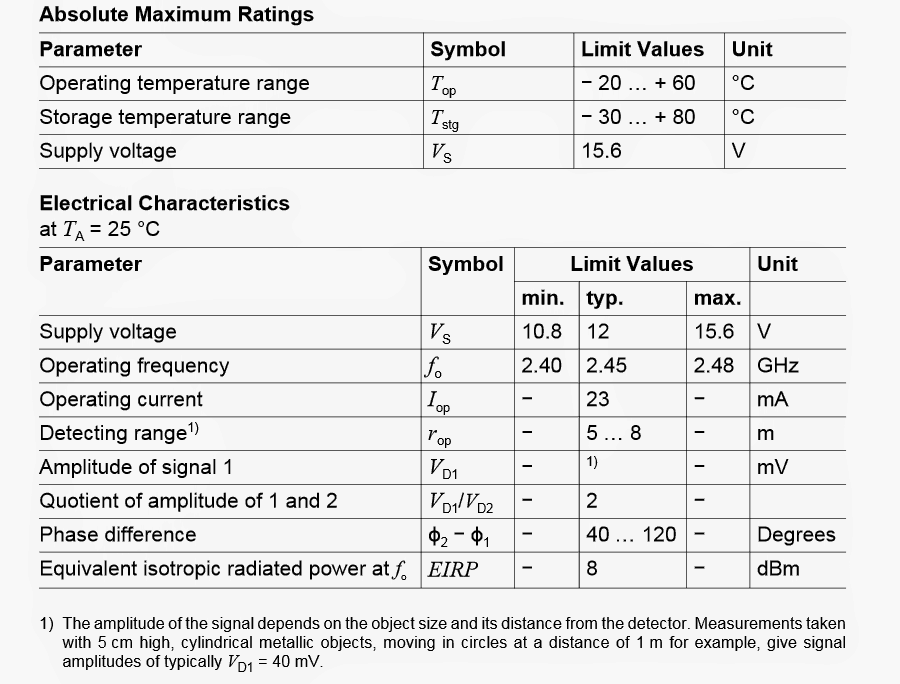
The next image provides the breakdown parameters or the absolute maximum voltage and current ratings that must be applied to the IC, these parameters must not be exceeded, to be precise these must be kept well below the shown values.
Maximum Electrical Tolerance Specs
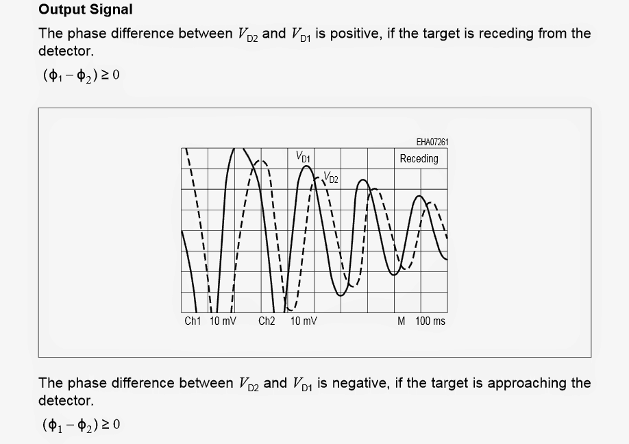
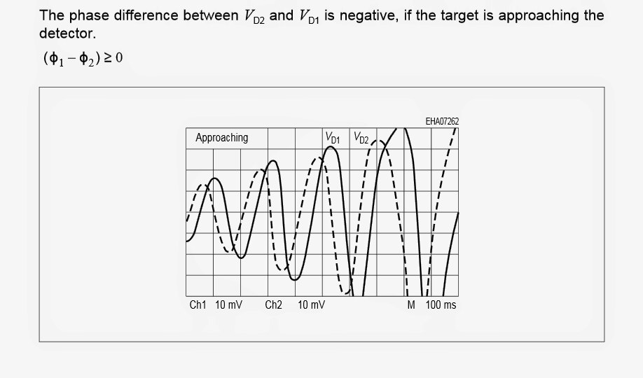
The two images shown below depict the phase shift or the difference in the position of the reflected frequency relative to the original radiated frequency when the target is approaching (first image below), and when the target is receding or going back (the second diagram below).
Analyzing Phase Shift Difference
In the next (upcoming) article we'll try to understand regarding how to use a microwave sensor through a practical circuit.


Questions & Answers
Thank you for providing resourceful information. I have a question and I would appreciate it if you help me to find it out.
I want to design a bistatic microwave detector by myself as my bachelor project. I do not know the diagram of transmitter and receiver, which type of electronic component should I use? Shall I use an Arduino board to process the receive signal?
I am glad you liked this site, however it seems I do not have this circuit with me at this moment. There is a related design available in this blog which you can refer to in the below given link…., in the meantime if I find any other new design will let you know about it:
https://www.homemade-circuits.com/ghz-microwave-radar-sensor-alarm-circuit/
I also checked this address, but I need more detail. I want to design and implement all details by myself. I do not have access to the KMY24 sensor. For example, I want to implement the MIT COFFEE CAN RADAR. Would you help me throughout this process?
I wish I could have helped you, but I myself do not have sufficient information about this subject therefore it can be difficult for me to help you in this regard.
No, it won't pass through opaque objects like the ground surface…