In this post I have explained a simple water sensor with pump starter circuit for switching a pump motor during municipal water supply periods. The idea was requested by Mr. Hitesh Thapa.
Technical Specifications
Is it possible to make a automatic water pump starter which turns On only when the city supply line has water flowing.
Here is the scenario.
- City Supply Line opens only for 1 hour anytime during 6AM - 10AM or rarely sometimes in the evening depending on the water guy.
- We need to keep a watch during these times and keep the main tap open to see if the water has come.
- Once the water has come, we turn on the water pump attached to the main supply line to pump water into our underground water tank.
Could this be automated, like we install some sensor between the water pump and the main supply line that detects water and turns on the motor only when the supply is in full flow?
I have made the water level indicator at home from watching some videos online and it works fine for the overhead tank at home but this one seems to be tough nut to crack :).
Any help is highly appropriated.
Thanks,
Hitesh Thappa
Circuit Diagram
Parts List
- Resistor 1k, 1/4 watt, 5% CFR = 1 no
- Capacitor 10uF/25V Electrolytic = 1 no
- Transistor TIP122 = 1no
- Relay 12V/30 Amp/ SPDT = 1no
- Diode 1N4007 = 1no
- Stainless steel metal for the probes
- 220 V AC to 12 V DC adapter = 1no
The Design
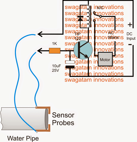
The circuit design of the proposed municipal water sensor with pump starter is very simple as may be witnessed in the shown diagram.
A Darlington TIP 122 transistor becomes the main active sensing device in the circuit. The device being a Darlington is very sensitive and thus becomes specifically suited to the application.
Its base and the positive DC are together clamped as probes across the water pipe mouth where the incoming utility water is intended to be sensed.
In absence of water the probes stay separated with air gap which renders a very high resistance across the probes which in turn keeps the transistor/relay stage switched off.
The 10uF capacitor at the base of the transistor ensures that the transistor does not get rattled or disturbed by external noises trying to make way through the sensor wires.
When utility water supply initiates, the pipe mouth begins throwing water into the adjoining tank, the speed of the water through pipe brushes across the probes creating a relatively low resistance across it.
This low resistance allows the positive DC to reach the base of the BJT triggering it into conduction...the transistor now conducts and switches ON the relay, the relay contacts shift position and switch ON the connected pump.
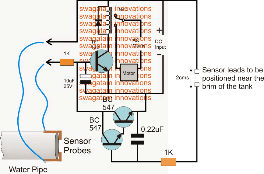
Upgrading the above municipal water sensor into an overhead tank overflow cut off circuit
The discussed circuit in the above section can be appropriately enhanced with an additional feature which will enable the circuit to sense an overhead tank full situation and switch OFF the relay along with the pump motor. The upgraded circuit design can be viewed below:
Parts List
- Resistor 1k, 1/4 watt, 5% CFR = 2 no
- Capacitor 10uF/25V Electrolytic = 1 no
- Capacitor 0.22uF PPC = 1no
- Transistor TIP122 = 1no
- Transistor BC547 = 2nos
- Relay 12V/30 Amp/ SPDT = 1no
- Diode 1N4007 = 1no
- Stainless steel metal for the probes
- 220 V AC to 12 V DC adapter = 1no

Questions & Answers
Sir, namastubhayam.mera sawaal ye tha ki mere water tank mein ek alarm lga tha jiska transformer khraab ho chuka hai kya main iski jagah transformer less circuit ka istemaal kar sakta hu agar haa toh x rated capacitor ki value aur zener ki value kya honi chahiye
Hello Ashu,
I won’t recommend a transformerless power supply, because it is not isolated from the mains AC and can be dangerous to touch, instead you can use your mobile charger or any readymade AC to DC SMPS adaptor.
If SMPS is used for the power supplies in the circuit using probes that touches water, due to any reason, is there ever no chance the water gets electrified or people get even minor electric shock from the water?
Modern SMPSs are very safe and perfectly isolated from the input AC mains, so there should be no risk of any leakage of 220V in water.
However, if you are still not sure then it is better to use a transformer based power supply. Furthermore, you can consider attaching the water with the earthing line so that even if there’s any minutest leakage it is safely grounded.
How to add timer relay where sensor probes are working? Water flowing in line is not known unless motor sucks enough water. Timer should run motor for 10-15 seconds and keep running if water in line otherwise close. In short, motor should turn on every 15 minutes for 10-15 seconds. If water is coming, motor will keep running otherwise keep trying.
I will try to design the circuit soon, and let you know once it is done….
I have designed the circuit, you can find it in the following link:
https://www.homemade-circuits.com/pump-motor-timer-circuit-with-dry-run-protection/
Hi Swagatam
Here my scenario
I am looking for a solution where automatic water inlet valve connected into municipality water line should open for adjustable time every day when water is detected in line.
Is it possible to achieve this?
Hi Joju,
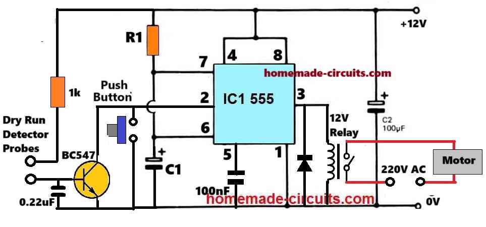
You can try the following design:
You can replace the motor with the inlet valve, or if the valve current rating is lower then 150mA then you can replace the relay coil with the valve.
Hi Swagatam,
Your prompt reply is appreciated.
I have following clarifications.
1. In my case, I feel the “Push Button” is nothing but the water sensing probes. Please confirm.
2. Since there is no motor involved, can I remove BC547 & 1K resistor, which are connected between Motor dry run probes?
3. What should be the values for R1 & C1, in order to achieve pulse duration of 5min ? The pulse duration is nothing but, water supply duration. Please confirm.
4. Every time the water sensing probes detects water, after no water, will retrigger 555 and generate pulse. Please confirm.
Thank you Joju, here are the answers.
1) The points marked as “Dry Run Detector” are the sensing probes. The push button is not required for your application, please remove the push button.
2) As mentioned above, the BC547 circuit is required, and cannot be removed.
3) R1 = 580k, C1 = 470uF/25V.
4) Yes, each time the water is detected across the probes, the 555 output will repeat the timing sequence.
Hi Swagatam,
Thank you very much for your support.
I will follow your advice and I will come back, in case I am struck.
Thank you once gaian.
Joju Xavier
No problem Joju, let me know if you have any problems with the circuit…
Hi Swagatam,
Thank you for your help. Do you have any idea of a floating valve that has both manual control and an electronic relay switch? We need to install it in one of the water tanks, which will turn off the UV as well once the tank is full.
Hi Mustakeem, are you referring to the following concept:
https://www.homemade-circuits.com/float-switch-water-level-controller/
Sir,u provide me ready circuit
Hi Krishan, sorry, I cannot provide readily built circuit, you will have to build it yourself, I can only assist you in the building process…
Good morning. Can you guide us in installing some sensor between the water pump and the main supply line that detects water and turns on the motor. And kindly provide your contact details. Tks & Rgs K.Suryakumar mob: 9600483771
Good morning. The sensor can be simply two metal wires held at a distance of 1 inch, as shown in the diagram above.
Hi Swagatam
Due to our house is the last in the water supply pipe line. The sensor can’t detect the water. Previous house pumps in our lane has taken all the water. We have to suck water with a Texmo self-priming pump to get water to the sensor. Can you suggest a sensor with timer so that motor doesn’t run dry if the municipal water supply is missing that day due to man power?
Best Regards
Gurmel
Hi Gurmel,
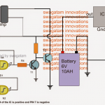
You can try the following simple design for protecting the motor against dry run:
Hi,
How can we reach out to you. We are part of a social initiative related to water conservation and would like to talk to you to understand how we can use this as this would help a lot and have a vast application. please share your contact details for further discussions.
Hi, sorry, I am mostly busy with my blog, so can’t participate in external jobs. If you have any doubts or questions please feel free to ask me here, I will try to solve it for you!
Can you make a PCB layout for both the circuits? And upload the template.
Thanks
Can you make youtube video of Municipal water supply sensor controller circuit please
In my free time I will try to make a video…
I want this circuit. Kindly Contact me.
Hello, the circuit really works .. But what happens is that the tips have been corroded for a while.
Glad it worked, you can try replacing the metal probes with graphite probes
Sir, can I use 5V relay and 5V dc supply also? Because it is easily available in mobile charger. Otherwise i have to buy 12V adapter
Hi Gaurav, yes that will do, but I don’t think a 5V relay will be able to drive a heavy pump motor
dear,
5 volt dc is for relay coil to trigger switching AC 230 volt for the pump.
5V relay might not have sufficiently heavy contacts to handle the pump motor current.
I have one more query, how can we connect 12 V dc relay to direct a.c with motor. I can not understand these connections
Please read this article to understand how a relay is connected with AC mains load
https://www.homemade-circuits.com/how-a-relay-works-in-circuits-how-to-connect-it/
Sir,
Please clarify, what is voltage used to power the circuit, as well, which relay is used in the article “MUNICIPAL WATER SUPPLY SENSOR CONTROLLER CIRCUIT(first normal circuit)
You can use a 12V relay and a 12V supply input
Hello sir, tip122 not working only on relay sensor point not working
replace it with two BC547 as shown in the second diagram lower side.
I already have it with a 100k resistor and a 100nf capacitor at the base of Gnd and it works well for years.
Swagatam Sir, I would like to know why you are using a TIP 122 transistor as a relay driver, because I feel a BC 547 or at the most a 2N2222 will be enough to drive even heavier relay. Please explain.
Hi Sanjay, 2 reasons for that, first TIP122 is a Darlington and will respond to water contact efficiently, secondly since the water pump relay may be quite big with coil resistance below 100 ohms TIP122 will easily handle it, BC547 may heat up and get destroyed with such relays. However, you an try two 2N2222 in Darlington mode, that will do the job equally well
Sri Swagatam
While I was checking up. With different pump manufacturers I came across your own project That is a sensor based Auto on and off for a motor connected to the Muncipal water system . I am a lay man a retired senior banker . However I have a relative who is good in electronic circuits . I request you to please forward me a circuit diagram along with the components so that I can request my relative to make one for me .
Thanks
Siva Rama Prasad
Hello Mr. M.Siva Rama,
The diagram shown in the above article has all the required information regarding the wiring and the parts details. If you show this to the concerned engineer, he will be able to make the prototype without any problems.
Still, if you need any further assistance please feel free to contact me here.