In this post I will comprehensively discuss how to build a high power 1000 watt induction heater circuit using IGBTs which are considered to be the most versatile and powerful switching devices, even superior to mosfets.
Induction Heater Working Principle
The principle on which induction heating works is very simple to understand.
A magnetic field of high frequency is produced by the coil present in the induction heater and thus in turn eddy currents are induced over the metal (magnetic) object which is present in the middle of the coil and heats it.
In order to compensate the inductive nature of the coil, a resonance capacity is placed in parallel to the coil.
The resonant frequency is the frequency at which the resonance circuit (also known as coil-capacitor) needs to be driven.
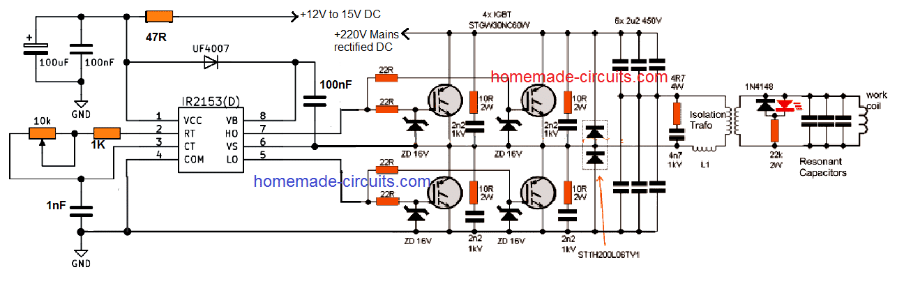
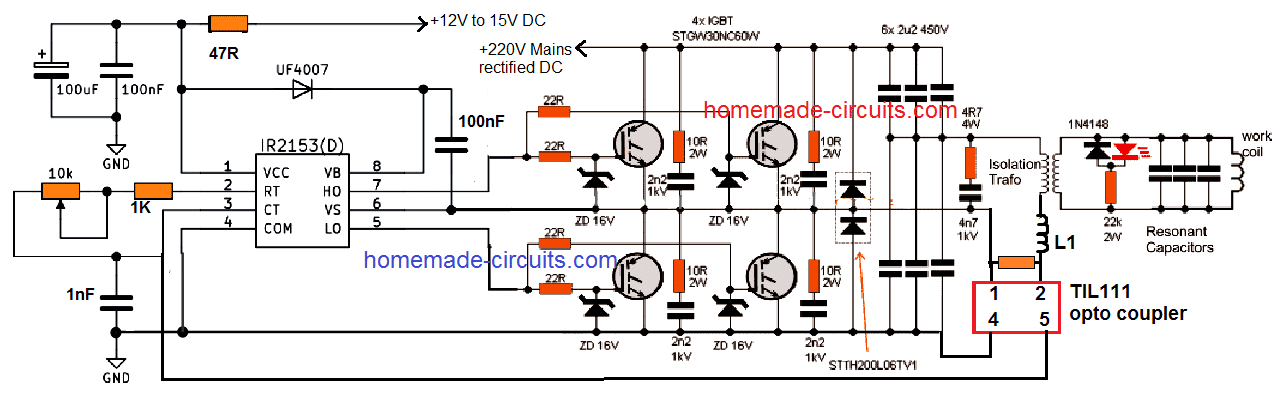
The current flowing through the coil is always much larger than the excitation current. The IR2153 circuit is used to enable the working of the circuit as a “double half-bridge” along with the four controlled IGBT STGW30NC60W.
An equal amount of power is delivered by the double half-bridge as to the full bridge, but the gate driver in the case of the former is simpler.
IGBT STGW30NC60W
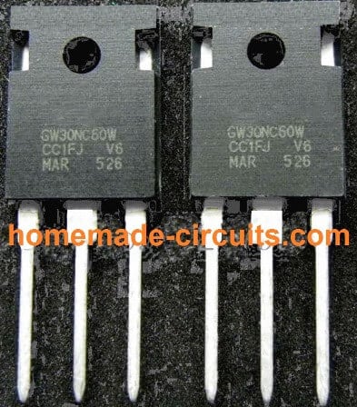
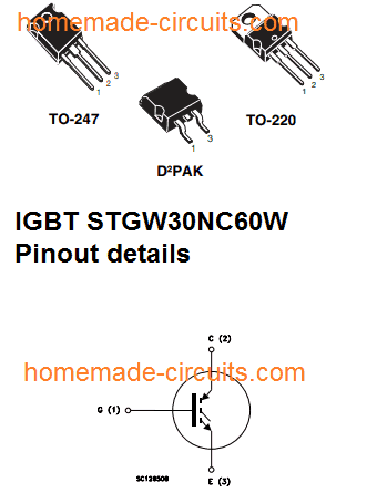
Using Anti-Parallel Diodes
The large sized double diodes STTH200L06TV1 (2x 120A) are used in the form of anti-parallel diodes. Even if the smaller diodes of 30A size will be enough for this.
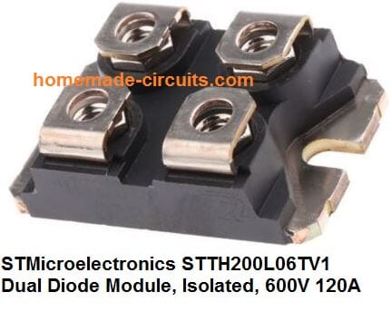
In case you use the built-in diodes of IGBT such as STGW30NC60WD, then you will not be required to use the smaller diodes or large double diodes. A potentiometer is used in order to tune the operating frequency into resonance.
One of the best indicators of the resonance is the LED’s highest brightness. You can certainly build drivers which are more sophisticated depending on your requirement.
You can also use automatic tuning which is one of the best things to do, which is the course adopted in the professional heaters; but there is one drawback that the simplicity of the circuit will be lost in this process.
You can control the frequency which falls in the range of approximately 110 to 210 kHz. An adapter of little size which can be either transformer type or smps is used to provide 14-15V of auxiliary voltage which is required in the control circuit.
The Isolating Transformer
An isolating transformer and a matching Choke L1 are the electrical equipment which are used to connect the output to the working circuit.
Both these inductors are present in the air-core design.
On one hand where a choke consists of 4 turns on a 23cm diameter, the isolating transformer on the other hand consists of 12 turns on a 14 cm diameter and these turns are made up of double wired cable (as shown in the figure given below).
Even when the output power reaches to a scale of 1600W, you will find that there is still a lot of scope for improvement.
The work coil of the proposed IGBT induction heater is made up of a wire which is 3.3 mm in diameter.
Using Copper for the Coil
A copper wire is considered more suitable to make the work coil as it can be connected easily and effectively to the water cooling.
The coil consists of six turns along with the dimensions of 23 mm height and 24 mm diameter. The coil can get hot in case it is subjected to prolonged operation.
Resonance capacitor is made up of and consists 23 pieces of capacitors of small size which has a total capacity of 2u3. You can also use capacitors of 100nF in the designs such as Class X2 and 275V MKP polypropylene.
You can use them for this purpose even when they are basically not intended or made for such purposes.
The frequency of resonant is 160 kHz. EMI filter is always recommended to be used. A soft start can be used in order to replace the variac.
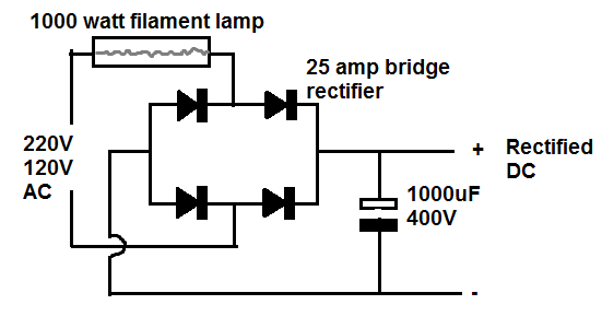
I would always strongly recommend you to use limiter which is connected in series with the mains such as halogen lamps and heaters of approximately 1 kW when it is being turned on for the first time.
Warning: the induction heating circuit being used is connected to the mains and contains voltage of high level and can be lethal.
In order to avoid any accident due to this you should use a potentiometer which has a plastic shaft. The electromagnetic fields of high frequency are always harmful and can have a damaging effect on the storage media and the electronic devices.
A significant level of electromagnetic interference is caused by the circuit and this in turn can also cause electric shock, fire, or burns.
Every task or process which you carry out is at your own risk and the responsibility will lie with you and I will not be responsible for any kind of harm which comes by in carrying out of this process.
Circuit Diagram
PCB Design
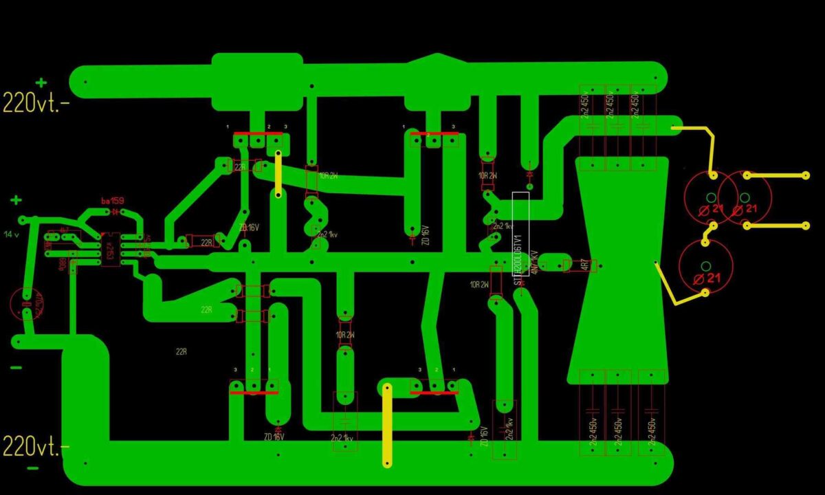
The following PCB design for the above IGBT induction heater circuit was provided by an avid reader of this blog Mr. Атанас.
220V AC to 220V DC Bridge Rectifier Circuit with Safety Lamp
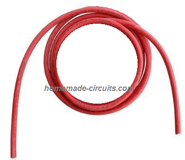
The Choke L1
The design of the choke L1 used in the above full bridge IGBT induction heater circuit can be witnessed in the below given image:
You can make this by coiling 4 turns with 23cm diameter, using any thick single cored cable.
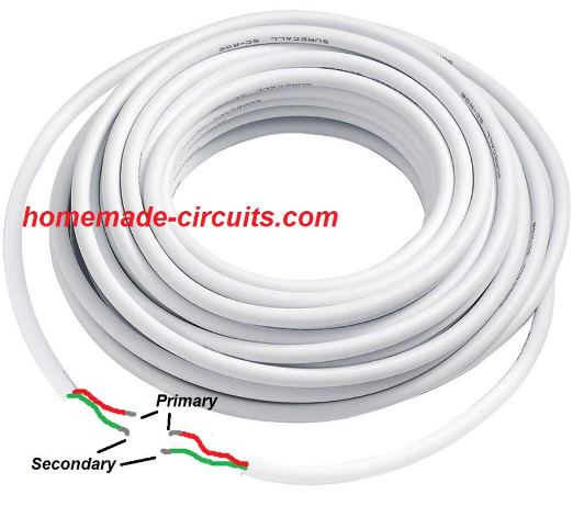
The following image shows the double coiled air cored isolation transformer design:
You can build this by coiling 12 turns with a 14 cm diameter, using any thick doubled wired cable.
The work coil may be build as per the following instruction
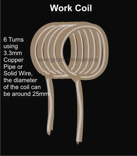
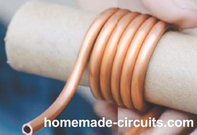
Please note that if the coil is tightly wound then only 5 turns may be required. If six turns are used then you may try stretching the coil slightly for achieving optimal resonance and efficiency.
UPDATE
Adding a Current Limit
The following diagram suggest how a simple current limiting feature can be added to the above explained induction heater design.
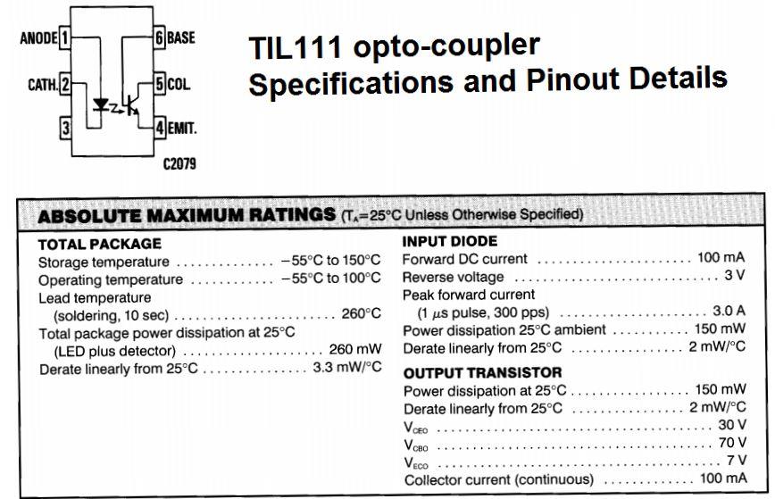
TIL111 opto-coupler Pinout Details
Here the resistor near L1 (let's call it Rx) becomes the current sensing resistor, which develops a small voltage across itself to the desired point when the current begins exceeding the safe limits.
This voltage across Rx is used for triggering the LED inside the attached opto-coupler. The output transistor inside the opto responds to the LED triggering and quickly conducts grounding the Ct, pin#3 of the main driver IC IR2153.
The IC shuts down immediately prohibiting any further rise in current. When this happens the current drops which in turn eliminates the voltage across Rx, thereby switching OFF the opto LED. This reverts the situation towards earlier normal situation, and the IC starts oscillating again. This cycle now repeats rapidly ensuring a constant current consumption for the load, within the predetermined safe limits.
Rx = 2/Current Limit
Feedback from one of the dedicated readers:
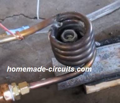
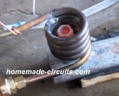
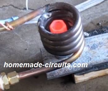
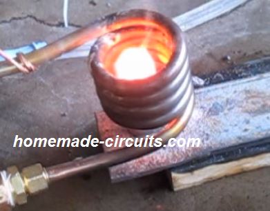
Dear Sir- I have successfully made induction heater 1/2 bridge with 4 IGBTs and i want to know that the 1000 watts heater lamp that's been suggested should be permanently connected to the circuit or only upto testing for the 1st time.
Images of the test result are enclosed here under:
Awaiting your reply at the earliest. Regards - Manish.
Solving the Circuit Query
Dear Manish,
While operating the induction heater do you see any glow on the series lamp?
If yes then probably it cannot be removed, if the lamp is in the non-illuminated state and completely "cold" (feel it by holding it) then it can be removed.
Regards
Feedback from Mr. Saeed Mahdavi
Dear Swagatam:
At last I was able to make my circuit work again after a lot of more attempts. And i shot the video with the bolt red hot.
I hope it could be useful for those interested in induction heaters. Would you please tell me how to increase the heat so that the bolt reaches melting point?
The voltage across the mains is 194 volts and the current consumed by the circuit is just 5 amperes and the wave form on the oscilloscope is quite sine waveform.
In my prototype I added a few turns to the RFC choke to get more voltage on the work coil and consume less amp.
The IGBTs worked quite normally without much heating during the operating period. Would you please tell me what I should do to get more and heat. Thanks a lot
Saeed Mahdavi
Video Clip:



Questions & Answers
Can you publish a circuit automatically controlling a ceiling fan according to room temperature. I mean it should increase / decrease speed according to variation in room temperature.
please refer to this post:
https://www.homemade-circuits.com/2013/01/automatic-temperatureclimate-controlled.html
Sir i am m. Tech scholar from new delhi.. I need a induction heating setup with temperature controller to heat (red hot) stainless steel (cross section 14mmx 10mm) .. The temperature capacity of setup should be in range of around 500 degree celsius to 1000 degree celsius ) .. How much it will cost and where from I will get the same.
Hello Fam, The temperature will depend on the time. Longer the time, hotter the iron will get. I think a 1000 watt induction heater should be enough for your application. You can easily procure it from any online vendor.
I am in the process of designing a circuit for analysis purposes and might some some help. Do you consult on electronics matters?
Best Regards
Paul
If it's related to the above induction heater circuit then I am afraid I won't be able to provide much help because I haven't tried it practically yet.
….If it's related to other concepts, within my range, I would surely try to help you out through comments in this blog.
Please tell me can i skip double diodes from above circuit?
STTH200L06TV1
Please see i made changes like this.. is that ok?
https://drive.google.com/file/d/0B3Pn7Yg7DiqkTURzRWxpdm5peE0/edit?usp=sharing
thanks
The diodes are for protecting the IGBTs from coil back emfs, those are compulsory and must be included.
Hello. some help please. Can I apply a single 6.6uF 450V capacitor (one to the top and one to the bottom) in place of 6x 2.2uF? Second, what should be the value of the resonant capacitors?
Thank you.
Hello, a single capacitor will not be able to handle the high current specs of the coil and could burn…therefore many in parallel is recommended.
the work coil resonant capacitors are made by joining 23nos of 0.1uF/400V capacitors in parallel
Please tell me whether there is any relation between the choke L1 and 6 X 2u2 capacitors used, like any resonance or not. What for the choke is used and how it's value selected?
L1 has no relation with the 6 x 2u2 capacitors, L1 is only for limiting current and filtering harmonics.
Please tell me about ferrite core use in L1. There is no ferrite core used in this. Also about the henry reading of L1.
All the inductors are air cored, that is without any core….see the green wire and the white wire coils, those are the inductors.
i am confused about working coil. it is too small. is it enough to heat or melt.
any iron inside the coil diameter will become red hot…
Hello. I have a couple of questions. If I replace the 15V supply by 12V would the controller working properly? And the diode BA519, is it a simple diode or zener? Because the symbol on the schematic confuses.Thank you
hello, 12v would proportionately reduce the output power of the heater (by about 3×20 = 60 watts)
BA159 is a fast switching rectifier diode, it's not a zener diode
Hello. If I use 12V supply instead of 15V will be ok?
please see the above comment….
Hello. About L1 and transformer coils does matter if I place them the one above or inside the other?
No, preferably these must be kept isolated from each other
Hello. I see many that apply the working coil into water for cooling. If i do so, will matter if I apply the transformer coil leads into water too? ( only the leads connected to working coil not all the transformer coil)
I don't think it would cause any problems but make sure the wires are insulated and do not short circuit into the water which could result in a disturbance in the generated frequency and resonance.
Dear sir
What wattage of resistors that 4k7 used at pin 2&3
And also what wattage of resistors that 22r used at pin 5 & 7
Dear Raj, all are 1/4watt except the ones which are specified with their wattage rating.
instead of air core for L1 & isolation transformer one can use ferrite core ? what is mH or uH value of both ?
Nope, ferrite core will not do, it has to be air cored as recommended in the design
uH cannot be measured since it could be very very small in magnitude
instead of air core for L1 & isolation transformer one can use ferrite core ? what is mH or uH value of both ?
Dear sir swagatam
At last I did the sstc based on this schematic sstc4.png – https://docs.google.com/file/d/0B8xT7Q4vaK-bYVRTTnRseHZqb1U/edit?usp=docslist_api
Its worked well for 10minutes with 1inch spark output on secondary coil .but after 2nd start the igbts blow out like crackers suddenly .
I have know idea what went wrong with it .I checked the entire circuit for ani short connections.. But its all well.
Plz suggest any trouble shoot
Thanks
Regards
Raj
Dar Raj, just like mosfets an IGBT can be susceptible to high gate voltages or high load currents and also transient spikes, troubleshooting can be difficult without a lot of practical effort….
try driving the IC with 9V or 12V and use a 200 watt bulb in series with the mains input line while checking, check the response.. how it goes.
makes sure the IGBT gate links with the IC is very close, and not too far away
Dear swagatam sir
Thanks for your valuable suggestions.
Here is one more doubt
What are the symbols are they mentioned at point pin 9 of tl494 and at collector pin of transistor vn 10km ..and also at diode uf4001 points in this image sstc01.gif – https://docs.google.com/file/d/0B8xT7Q4vaK-baUY2Z3U5S2FDNHc/edit?usp=docslist_api
Are they are sine wave symbols or connection by pass symbols
Dear Raj, those are square-wave symbols
sstc02.gif – https://docs.google.com/file/d/0B8xT7Q4vaK-beGpRY1ZwVW5ESG8/edit?usp=docslist_api
In the above image what is mean of 470k 1/2 w 500v.. . as I know 470k 1/2w is a resistor but what about 500v mean ??
2) what is mean of k =0.4 between primary and secondary of coils
Thanks a lot in advance
It may be the voltage rating of the resistor, because normally resistors are designed to tolerate 300V max, you can use two 220K resistors in series in its place
k=0.4mm could be the maximum distance between the winding which should not be exceeded for maintaining optimal performance
Dear sir swagatam
Plz tell me the substitute transistors for
ZTX 450 , ZTX550 and VN10KM MOSFETS for this circuit
sstc01.gif
https://docs.google.com/file/d/0B8xT7Q4vaK-baUY2Z3U5S2FDNHc/edit?usp=docslist_api
Dear Raj,
The closest equivalent seems to be the 2N2222 and 2N2907 transistors, you can try these out.
Dear swagatam
Based on this I have reached to Induction heating but now I am using water cooled copper coil and Want to melt small amount of aluminum inside 30mm inside dia of coil but present circuit is not able to supply more than 1A power so i want circuit with 2kw power and 200khz frequency ..but I don't know how to design that circuit please help me.
Dear Vivek, did you try the above design, it will definitely help you to reach the intended 2 kW power by suitably upgrading the "work coil"
Thank u for your reply .
but the problem is i don't know how to upgrade the present work coil to 2 kw power? please help me to upgrade the present coil…
sir,what is the output range of 25amp bridge rectifier?can you please suggest circuit diagram of 25amp bridge rectifier.
Sarath, if you are asking about the voltage and current handling capacity, the answer could be found in the datasheet of the specific device.
however a 25amp diode could become hot at 20amp current, so a heatsink may be required for it.
BSM 75 GB 120 DLC USED OPTO 3120 PLEASE SAND ME FULL DETAILS AND DROING
my dear such a good contribution thanks in advance for asking a favor quisera see waves resonate to compare circuit because my gives a pure sinusoid and the output of the coil have the same waves thanks
Hello sir, I have made this circuit but even I give the 60 volt to the circuit after 30 second the igbt burnt out…what is the problem? I use buitin antiparallel igbt
sorry abhijit, it will be difficult for me to troubleshoot your circuit from here because I don't know what fault you might have done in circuit connections
Sir, please let me know about the specifications(Strand & Gauge) of L1 coil(Green) and isolating transformer(White) wire..
Arijit, you can use a 3/20 insulated wire for both the coils for max safety
hello sir
sir please let me know about the gauge and strand of the wire used in L1 coil and isolation transformer.
suvradip samaddar
How will i make double coiled wire with 3/20 wires for the isolating transformer? will i take 2 .. wires and wound it as per the specification? please explain it a bit sir…..
the idea is shown in the image using white wires. Use two double-core wires as used for irons or heaters etc…coil them together as shown in the image
each wire should have two internal isolated wires (2-core wire but thick ones)
During the circuit test, 5 IGBTs are gone….
Are you sure about the authenticity of the German circuit?
Please tell me ASAP.
Now I am totally dependent on your reply,If you can assure me,that the circuit is correct,then only I can proceed.
this circuit is a tested and verified design, but said that the design will require extreme knowledge of switch-mode circuits from the user, because if there's a slightest mismatch between the inductors and the frequency could cause an instant damage for the devices, and so the circuit has to optimized by your self expertise in the field, this circuit is not one of those which will start working just by building it correctly as per the diagram.
the AC mains is shown with a 1000watt halogen lamp for dropping current, did you include that in your circuit?
You can try a 400 watt bulb initially just to make things safer and see the effects on the output, whether the work coil heats up of not
Is it going to create any problem if I use STGW30NC60KD instead of STGW30NC60WD?
please compare the datasheet specs of the two for getting the exact info.
When the load and the 100 Watt series lamp was connected we got an output of 0 Volt at the 6*2u2 capacitor terminals.
Then we removed the load, and applied voltage by the variac instantaneously we got almost same output that of the input at the 6*2u2 capacitor terminal. But gradually it damped up to 2 Volt.
We tried to measure the frequency at that terminal, but when we connected it with CRO, the MCB tripped down.
We also checked voltage input into the 20Amp bridge rectifier, but it showed only 2 Volt, when 100 Volt was given from variac, and the series bulb was glowing almost brightly.
Till then IGBTs were working properly. At last we removed the series bulb, and applied only 7V from the variac, the voltage input at the bridge rectifier was also 7V. But suddenly 2 IGBTs got damaged.
Through out the whole process, the current reading in the clamp meter was showing 0.02Amp
the coils must resonate with the applied frequency, until this does not happen the circuit will keep getting damaged and not work.
there could be a few related videos on youtube which you can see for more info.
dear sir.
How can we detect resonance of LC tank circuit without OScilloscope?
dear waqar, you can probably attach a series bulb with the circuit, as long as this is illuminating would indicate no resonance, and as its glow begins decreasing you can anticipate a resonance taking place.
Good day
Thanks for your interesting electronics
So my question Is :
Can I use a CFL lamp as power supply for feed your interested circuit
thanks, no that's not possible and not recommended
Hello Sir,Is there any possibility or way to check this circuit if we didn't connect part after L1.
I am looking forward to use this circuit for Induction Cooker and for that If i purchase ready made coil out there in market.So how can I select resonant capacitors for same ?
Plz guide me sir That would be great Help.
Hello Urmil,
for the basic tutorial you can refer to the following article
https://www.homemade-circuits.com/2016/09/designing-induction-heater-circuit.html
can i use this IGBT FGA25N120ANTD in this circuit?
if its voltage and current handling capacity is rated to handle upto 500 watts or more then you can use it.
Dear Swagatam Majumdar,
I want to change the work coil to 80mm inner diameter, 260mm long, 23 terns. That mathematically means approximately 11.25uH. Also mathematically means that I need to place capacitors in parallel approximately 56nF for frequency 200KHz. (please let me know if I did something wrong in mathematics). Now, doing those changes do I need to change anything else in the circuitry in order to work?
Thank you Nicos
Dear Nicos, sorry I have not yet investigated the formulas for calculating the parameters, since this is not my design so i won't be able to confirm your results.
By the way you can take the help of the following software to get the required info or check your calculations:
https://www.homemade-circuits.com/lc-resonant-frequency-calculator-software/
Thank you dear Swagatam.
Now I want to make this circuit more proportional. I want to control the power output by adjusting a potentiometer.
From my experience that could be achieved by controlling the gates of IGBT.
Is there any pins of IR2153 where I can place an extra circuit to control the gates? Or can be achieved by simply adjust the voltage input of IR2135?
Do you suggest anything else?
Also, after initial starting, can I short the 1000W halogen to get the maximum abilities of the circuit and also extend the halogen's lamp lifetime? Or it is not recommended?
Thank you
Nicos
Dear Nicos, the pin Ct of the IC is the shutdown pin, if you ground this pin the IC and the IGBTs will shut down.
If you apply a PWM (negative pulse) at Ct and adjust this pWM then the circuit power can be controlled by varying this PWM.
the 1000 watt bulb can be bypassed but if the input voltage fluctuates then the IGBTs could get damaged, to protect again the Ct pin can be used and configured with a current limiter stage which may ground the Ct pin each time the output consumption goes above a certain safe value.
Dear Swagatam Majumdar,
I am trying to get through this circuit but looks impossible. I burned up to 20 IGBTs and still going and some times the large diodes. I power up the system and IGBTs start get hot until burn. If I power up, shut down and then power up again, immediately burns and crack the IGBTs. I check the circuitry over a hundred times and it is all the way correct.
Could you please define the correct state of the halogen lamp? It should illuminates once or always illuminates?
In my circuit I used a 250W halogen and it is always illuminates. It is illuminate once only if I power the system without IGBTs.
Then the 4.7K potentiometer for the frequency should be at the correct place corresponding to the LC tank? If it is not could be damage the IGBTs? If can damage how can I set it to the correct position?
Please I spent a lot of time and money for this one and I definitely have to make this circuit work. Please help!!
Dear Nicos,
It could be difficult for me to troubleshoot your circuit without seeing it practically, please understand that this is a resonant based circuit which can be extremely unpredictable and sensitive, unless you are an expert dealing with such concepts it could be very difficult to make these work.
first of all, resonant circuits do not have a standard working condition, they will work satisfactorily only while they are within the resonant zone, however the moment this zone is disturbed or shifted the circuit will turn into a "short circuit" therefore maintaining a perfect resonant condition is the key to keep this circuit working.
Another thing I see is that you are asking what should be the state of the lamp, which indicates that you are a newcomer in the field.
anyway the answer is, obviously the lamp should be completely shut-off or glowing dimly, and this should happen only while the metal within the work coil is heating up nicely.
If your lamp is glowing constantly it means your circuit is not in the resonant zone, rather behaving as a "short-circuit"
remember resonance condition will occur when you hit the exact right frequency and while a ferromagnetic metal is placed inside work coil.
always keep a metal inside the work coil while testing and adjusting the frequency, as soon as you strike the resonant frequency you might find the lamp instantly getting dimmer and the metal inside the work coil beginning to heat up.
I would recommend you to first try other smaller circuits and then comeback to this one once you have learned all the aspects of the design
Dear Swagatam Majumdar,
Fist of all, thank you for spending time to help all of us here.
I knew the correct behavior of the lamp but after so many failed tests I start doubt.
Most probably my problem here is that I am not in the resonant field.
I made a circuit board and I can take a few pictures of my circuit that I can send them to you to have a look. You may see something that I am missing.
Is it possible to send a file to you? If yes can I have an email address to send?
Dear Nicos,
you can send the images to my email: admin @ http://www.homemade-circuits.com
however just by looking at the pictures I don't think I would be able to troubleshoot the fault, because there are so many parameters involved and pinpointing the fault could be difficult.
Dear Swagatam Majumdar,
Of course you cannot troubleshoot my circuit from a picture but you may see something wrong. The resistors and capacitors may be to far or to close, or the coils and transformer may be not good for example.
I did a test now. I fill the work coil with metal and turn it on. The lamp still lights constantly at any position I turn the frequency potentiometer. It is obviously that my circuit works as a short circuit for a reason.
IR2153 looks to be working because it is shutting down the IGBTs when I short pin 3 Ct to ground.
Nicos, you should first become well versed with induction heater concept and everything related to its working only then you will be able to troubleshoot the problems correctly.
you can refer to the following article for getting some idea regarding the concept
https://www.homemade-circuits.com/2016/09/designing-induction-heater-circuit.html
Hi Swagatam…
Can you tell me igbt for replace stgw30nc60w,because there isn't this igbt in my country..
Thanks
Hi Aris, please check the datasheet of the IGBT, once you know the voltage current specs of the device you can replace it with any matching IGBT having similar specs.
ok thanks
tell me I made change IGBT STGW30NC60W
Hi swagatam…
I check output from ic ,pin5 & 7 disconnecting from gate IGBT,duty cycle is 30%…is it correct??
(data sheet ic duty cycle fix 50%)
Hi Aris, if the datasheet says 50% then it should be 50%
Please build it only if you are an expert with switching circuits, and high voltage circuits, otherwise not, because this design is not suitable for the newcomers.
Hi sir,can you provide a final circuit with component details of induction heater please sir
Hi Saketh, everything is furnished in the above article, please copy them on a notepad accordingly…
please try a smaller one first and then attempt this one
Hi Swagatam, thanks for your posts, I used ones…are super. Please, is possible use this power circuit to Ultrasonic Langevin Piezo Transducer, change the final and with impedance coupling?
Carlos Benincasa
Thanks
Hi Carlos, I don't have mush idea regrading your device so it would be difficult for me to analyze the integration, however if you can provide more details regarding the specs and the operating principle of the device, I may try to suggest my views
Hello Dear..
First of all thanks for making such a nice & informative website 🙂
In the article above i found this line..
"In case you use the built-in diodes of IGBT such as STGW30NC60WD, then you will not be required to use the smaller diodes or large double diodes."
TO my understanding the above line means if i have IGBT with internal(built-in) diodes then i can change my circuit to
https://drive.google.com/file/d/0B3Pn7Yg7DiqkTURzRWxpdm5peE0/edit
means i can skip big antiparallel diodes?
Am i right?
Thanks Waqaar, I am glad you liked my site.
yes that's right, however I would not recommend removing the external protection diodes, after all the IGBTs are too important for the circuit and we would want to provide extreme protection for these device even if it costs little more to us.
Dear Swagatam:
first of all, i thank you for all useful information you kindly gave me. concerning the induction heater with 4 IGBTs in your webpage , i should say I made it at last successfully. thanks God. it was all OK having little illumination in the 1200 watt lamp in series. while working, the coil got so hot and the bolt in it got quite red. however, i was intending to see the bolt melt, so i increased the wattage of the lamp to 1800 which caused one of my IGBTs to burn out after a few minutes.
1-Now would you please tell me if i have to keep the 1200 watt lamp in the circuit for good , which in this case i would have just a moderate heat not able to melt iron.
2- what else i should do to get to that heat?
3- if i could omit the isolater coil, which is contained of 12 turns of wire?
4- if i could change the 4 turn choke with an air cored one to a smaller one with feritte core?
thanks a lot
Saeed Mahdavi Asl
Dear Saeed,
I am glad you could make it successfully.
However since this was not designed by me,providing perfect solutions may not be possible for me.
I would recommend you to keep the circuit as it is, and add a current limiting stage as shown in the updated diagram above.
Once you configure the current limiting stage, you can try removing the 1200 watt series lamp and check what happens.
The current limit should be set with regards to the breakdown limit of the IGBTs and other relevant components.
Dear Swagatam:
just a health concerning question,
as you have mentioned in your post, this circuit makes so powerful radiation. do you think it might be dangerous for its operator or it is quite safe??
have you ever researched about it??
thanks a lot
Saeed Mahdavi Asl
Saeed, as per my assumption the radiations may not be harmful to the user, because we have mobile towers at every corner of our cities and those radiations are much powerful than this, so if those are not a concern then this situation can be also ignored.
Dear Swagatam:
I am really upset with my circuit. it has quite little heat,just as hot as making a wrench head red and not more. and when i boost the wattage of the lamp in series to get more heat, i lose two of my IGBTs (gw35hf60wd). i used these IGBTs , as i could not find the one mentioned in the schematic. on the other hand i am after melting iron and making it red. please help me what i should do so that my IGBTs remain safe on the hand and i can get as much heat as to melt iron on the other.
meanwhile, i was waiting to get to the heat and shoot a film, but …..could not yet
thanks a lot Saeed Mahdavi Asl
Dear Saeed, I am really sorry I do not have much idea regarding the design since it was created and tested by another person, according to whom the circuit worked perfectly. It is the frequency which actually affects the heat, so make sure it is best optimized perfectly while the load is placed in the coil
Hello,
I want to know that if I touch work coil will i get electric shock? What is the voltage inside work coil?
If i wont get electric shock please tell reason.
Waiting for your kind reply.
Thanks
yes you may get a shock, since it is electromagnetically linked with 220V mains.
Can i start with small voltages like 24v
will it work for this voltage?
yes it might work but the work coil might also need some change, are you new to this concept, then I won’t recommend this circuit
Can you describe the operating principle of the diagram?
The IC is a half bridge inverter IC which drives the IGBTs in the half bridge mode, and oscillates the respective coils at a high frequency as determined by the RC network at pin2/3 of the IC. The frequency finally oscillates the work coil at the resonant frequency executing the intended induction heating. Hope you got it.
thank you so much!1
How components like resistors or diodes and capacitors are calculated or chosen
Diodes are for allowing current to flow only in one direction, and for converting AC to DC. For resistors you can read the following articles:
https://www.homemade-circuits.com/use-resistors-design-circuits/
https://www.homemade-circuits.com/understanding-basic-electronics-how-to/
For capacitors you can read the following article:
https://www.homemade-circuits.com/understanding-capacitors-made-easy/
Hello dear friend How do we find out that our resonance or tank frequency is created ?
Dear Friend, you can find the details in this article:
https://www.homemade-circuits.com/simple-induction-heater-circuit-hot/
Hi dear sir i made this circuit and increased the power of this coil by using 3 separate circuits,Each of them is an example of your design. Of course, the IGBTs Trigger command is parallel, so there will no disruption to these three circuits And the outputs of the three circuits are connected through the circular ferrite that I did in the wiring star connection and tripled the work coil power and I could melt the steel and I wanted to share this experience with you Of course, I wrapped the copper tube 1.5 turns on the ferrite
best regards Sincerely yours
Thank you Sedigh, I appreciate your hard work and congratulate you on your success in upgrading the design to a much higher power output. Please keep up the good work!
Hello,
Above circuit limit current using negative shutdown signal.
how can i use TIL111 for current limiting ir2110 which is shutdown by positive signal.
Please give me circuit to shutdown ic using TIL111. IC requires positive shutdown signal.
Thanks
Dear mr. Swagatam,
How can I change from the air core isolation transformer to the ferriet core but the circuit does not change?
How can I cal them?
Dear nguyen, you will have to measure the inductance of the coils, and estimate their current handling capacity. once you have found them then you can build a ferrite based inductors with similar specifications.
Dear Swagatam
For the circuit shown (igbt induction heater)
Can I replace the 2u2 film capacitors with 1000u electrolytic capacitors for the half bridge converter.
Also what is the purpose of the RC network across the tank circuit(4n7 in series with 4R7) which is connected across the isolation transformer.
Thank you.
Dear Welensky, do you mean replacing with a single 1000uF/450V cap, no that won’t be appropriate. You will have to use many 2.2uF as shown in the diagram.
The RC network is for suppressing high frequency transients.
Dear Sir
You have used 2.2UF x6 tank capacitors at the output.
Sir, Can I know how the value is calculated?
We are designing for three phase input, 5KW output load.
Can you kindly let me know…
Dear poornachandra, the capacitors are calculated as per its LC peak resonance frequency through practical testing and oscilloscope readings. The freqeuncy and the LC values are matched and tweaked until the output amplitude is maximum. You can refer to the following article for more info:
How to Design an Induction Heater Circuit
Dear sir, this induction heater uses 4x igbt, the power is quite large, my first question is, by adjusting the frequency to around 50khz and replacing the inductor with a calculated ETD59 transformer, this circuit is the same as 3kw smps, no feedback voltage is needed. oscillator is also simple ir2153. the second question is, igbt is replaced with a similar data FGH60N60 and many in the market. please advise and thank you for sharing your knowledge
Hello Widiatmono, your assumption is correct, but the modifications might requires a lot of calculations. Feedback is not give but that means the circuit is vulnerable to short circuits and overloads
i am trying to build this on a PCB however i am having trouble finding away to integrate the anti parallel diode into the circuit board. is there something else i could use that will do the same job.
Diodes cannot be replaced by anything else. You must find a way to connect the diodes as mentioned in the diagrams.
Is there a reason this heater uses a control circuit to toggle the IGBTs instead of using a ZVS design?
It provides a wider optimization range for the user…
Thanks! I am not sure what “optimization range” is referring to here. Is it the range of LC values that you can use for the circuit, the range of frequencies that will work with a given LC value, or something else?
Yes, wider optimization for frequency, LC, current and voltage levels.
i am mecatronic engineer may languige farsi iran tehran low languig english your website very very good
Hello Swagatam, I benefit a lot from the information you have given, thank you very much. In the diagram you have given, these products are 4*IGBT STGW30NC60W, these products are expensive, I disassembled one induction cooker, 2200watt, this circuit works with 220v, only one H15 ME1 igbt is used in the circuit, I said let me make this circuit, but in the circuit ALP-01A C051X0008G1 integrated used, but I could not find this integrated anywhere from you. I need an induction cooker diagram like IHW 20N120R3 working with IGBT, I would appreciate if you could help me. Thank you so much.
Thank you Turan, I appreciate your interest, however I do not have the mentioned circuit diagram with me at this moment. If I happen to find one, will surely update it here for you.
Dear Swagatam, thank you very much for your interest. Thank you very much, I really benefit from your useful information, I hope you find the Induction cooker diagram that works with an IGBT transistor that I mentioned. Even if you can’t find it, best of luck. Thank you.
Thank you so much Turan, I appreciate your patience and understanding.
Hello Swagatam Teacher, I’m sorry to bother you to benefit from your valuable information. I found the induction cooker schematic working with 1 IGBT Transistor, I even bought an induction cooker. It didn’t work for me in this stove. What I want to do is to make an induction heater. I run this stove I bought. When it reaches a certain temperature, the stove shuts down and when it shuts down, I have to wait by it all the time. If the IGBT Circuit works on its own by making abbreviations in this diagram, I can achieve my goal by connecting a relay to the heater’s heat meter. Since I do not have the ability to design a circuit, if I send you this schematic, can you help me make an IGBT Transistor-operated heater? Thank you so much.
Thank you Turan, However, I am sorry to say that modifying an existing induction heater can be extremely difficult, since induction heaters require a lot of calculations, and doing modifications can be quite risky. Furthermore induction heater is a difficult concept and requires a high degree of expertise in the calculations, which I unfortunately do not have at this moment.
Bir IGBT ile çalışan indiksiyon ocak şemasını siteden biri sağolsun yayınlamış, bunu size gönderebilirim.
Пожалуйста поподробней о Rx шунта в обратной связи через TIL111.
How to convert my OGBT welding machine to a heater induction up to 2000C
Sorry, no idea about it!
Hello Mr. Swagatam, good morning. I want an all-bridge induction furnace circuit with a working frequency of 500 to 5000 Hz. Input 380 volts or 220 volts. Please help me. Thank you.
Thank you Hossein, I understand your requirement, however I do not have this circuit with me at this moment….if I happen to find it I will surely share it with you soon.
Hello Mr. Swagatam, thank you for your kindness. I really need this circuit. Please help me.
You are welcome Hossien, but I really do not have this circuit with me at this time.
I tested some circuits, but I did not get an answer, if you can help me
Actually, as you know high power induction heater circuits are complex circuits therefore it can be difficult for me to solve your problem without practically testing your circuit.
Yes, I know, but it can be a good experience for you and help me
I can understand your problem, but induction heater circuits are complex circuits we cannot judge the faults without a practical testing of the unit.
If there is a problem with the thyristor, thank you
Excuse me, can you find me? Thank you
Mr. Swagatam, if you can not test the action, give me your suggested command circuit and power. I will test the action.
I have some knowledge only about the following small circuits, my knowledge about high power full bridge induction heater is not good.:
https://www.homemade-circuits.com/simple-induction-heater-circuit-hot/
Dear Mr Swatagam, I’m wish somehow to use this circuit or similar for hitting the flat CCA 60 square m . How to use induction Heather (with made high temp) for very lower temperature. Pls answer me you or some else. Yours coleg with many little resources from Makedonija
Dear Petre,
A high temperature induction heater can be used to generate low temperature if the input current supply is sufficiently reduced to suit the application.
Hi … I am a great fan of your site. My problem here in South Africa, cape town is finding simple parts like laminated transformer plates. If possible, please connect me with a company to procure transformer parts like magnet wire and plates to build the 9-0-9 centre tapped transformer.
regards
angelo
Thank you so much. Presently I do not have any such contacts, but I will try to find somebody. If I find one I will let you know.
Hi we want to develop some induction circuit we pay you
Dear sir, please let me know how to find resonant capacitor value in this circuit?
Hi LGHD, sorry I do not have a formula for calculating this parameter.
Sir, then how you choice capacitor values in your circuit?
It is not my circuit, it was contributed by another author.
i am sorry to tell about the insulation transformer is totally inappropriate and ineffective
i suggest to make a real isolation transformer. use a PQ5050 ferrite core. no gap is required. i calculate winding turns for 220vac input wind primary and secondary with 8 turns of 14ga litz wire. that will be overkill transformer . at 160kHz you should have more than 1500watts.
For 240vac input, make 9 turns and for 120vac input, make 5 turns
Hi denis Laporte,
Did you make this circuit if coupd you tell me if it works with your isolation transformer?
Is this avg( american ) or standardised gauge (SWG)?
Dear sir, please can you explain the type of 2.2uf/450v capacitors are electrolytic or mylar?
Hi Deshan, those capacitors can be metallized polyestor or polypropelene (PPC) type. They should be strictly non-polar.
Dear sir, let me know can 30A diodes use for replacing STTH200L06TV1 this?
Hi Kumar, yes that will do, but it must be rated at 600 V and must be ultra fast.
Hi sir, please let me know the value of shunt resister near the optocoupler, it was not mention in the diagram
Hi Kumar,
The formula for calculating the shunt resistor RX is provided in the article.
Can I make a furnace circuit with a capacity of 100 kw and melt aluminum weighing 100 kg?
Sorry, that may not be possible with the above mentioned circuit.
Hello, I took the picture, but I have a problem, the lamp lights up and the circuit does not start. I can suggest a circuit. I get 5 volts at the output of the integral 5 and 7
Hi, first you must confirm whether you IC is oscillating or not. You must confirm this with a frequency meter and by adjusting RC timing components of the IC. Also your coil winding must be correctly configured with correct polarity.
I changed some elements, this time it heats up the diode on the integrated circuit. I sent you a circuit board to your email, if it’s good you can post it here
I could not find any email from you, in which email ID did you send?
Is the circuit working for you now?
I got undelivered mail
Thank you very much Атанас,
I received the PCB design sent by you.
I have posted it in the above article, under the first schematic.
IR2104 MOSFET/ IGBT Isn’t this integral better, the one on the circuit two circuits I made and burned some things.
I don’t think a MOSFET would be required to drive the IGBTs, the IGBTs can be driven directly by the IR2153 IC.
This circuit is a difficult circuit so you might have some initial problems. Try using a 200 watt bulb instead of 1000 watt for the initial testing.
With 200 watts, I also test two separate circuits of the IR2153, with one the lamp lights up, with the second, one of my transistors burned out.
Is your IC oscillating and generating the required frequency for the IGBTs? The 10k preset must be correctly adjusted to match the correct frequency. Also the coil must be correctly wound and configured, if there’s any mistake in the coil configuration, it will lead to over-current situation on the IGBTs.
Thank you very much for your help, if it wasn’t for you I would have stopped with the scheme. My smallest coil is 38 mm internal diameter 6 mm traba copper. The one I tested with is 62 mm. 6 turns. Should I use the smallest one?
No problem Atahac, I will try to help as much as possible.
All the inductors must be built exactly as given in the above article. If you change the specifications then something might go wrong.
The work coil must be 25mm in diameter with 6 turns of 3.3 mm copper wire.
Also, did you check the frequencies across the 1nF capacitor, pin7 and pin5, and by adjusting the 10k preset.
You should get a high frequency across these points and it must vary when the 10k preset is adjusted.
I replaced the burnt parts, made two integrated circuits, measured them with an oscilloscope. They gave 15 volts at the output, and I don’t know what this frequency is called, but there are small dashes above and below. With one circuit, the lamp lights up with the other one and goes out, but nothing happens. heats the meta.
Frequency is measured in Hertz. In the above circuit it should be in many kHz. You have to finely adjust the frequency by adjusting the 10k preset. If the frequency is not precisely adjusted then the circuit will fail to work.
Frequency is the most crucial aspect of the circuit.
Can someone who has managed to run the circuit tell me what values the RX resistance is.And a trimmer for a drill can be used for a smooth start of the scheme that it exploded again
Hi, this circuit was tested by Mr. Saeed Mahdavi, but I do not have his email ID.
You must adjust the frequency using the 10k preset with the bulb connected until the bulb glow becomes minimal. This will prove that the circuit is resonating perfectly.
Merhaba,
ikinci şemada L1 bobin bağlantısında bir hata var sanırım. Devre akımı Rx direnci üzerinden geçirilmiş.
Hi, the L1, Rx connection in the second diagram is correct. The L1 is for suppressing voltage spikes, and Rx is for detecting over current.
I am sending a diagram with corrections, I tried it at 110 volts, so far it has not started, I will try it at 220 volts.
I replaced the transistors with more powerful ones, but I don’t know if they are compatible. SGH80N60UFTU IGBT Transistor 600V, 80A, 195W
The IGBT looks OK to me, and should work. Just make sure to add a series bulb initially with the input AC and optimize the IC frequency correctly.
joke, I replaced a 100 k ohm potentiometer and a 10 kilo ohm resistor, the frequency is from 18 khz to 160 khz. One circuit is activated but the other is not, the zener has no voltage
I managed to run the board with a laboratory power supply of 20 volts. There is an error when connecting to the integral, the two terminals must be exchanged. But after 2 minutes I burned the integral, that’s why I soldered the two boards with transformer ferrites 2 double 25 coils at the input and 25 for the output. You need to play a little which cable to connect where matters. 0.6 mm cable
OK, thanks for updating the information.
I forgot to mention on the integral that the power supply must be adjustable 9 to 15 volts.
OK, thanks, noted!
There is no point in dealing with the frequency, deal with the beats.
good I am an amateur I would like to develop this circuit but I feel that I lack more knowledge about measures you could send me to the mail this circuit with all its values and conetions please I want to undertake myself in this world of electronics and more with induction heating thanks.
Hello Eduardo, I appreciate your interest in this project and I understand that you want to build it, however, the above project is not an easy DIY project and requires prior expertise in the field of induction heaters, therefore this project is not for newcomers, because if you happen to get stuck somewhere, I may not be able to troubleshot it for you, without practically checking your circuit connections, so I would recommend you not to try this project unless you have gained sufficient experience in this field….
If i wanted to turn this into a cooker would i just need to change the wire and its shape or would there be any other changes necesery?
Yes, you just need to modify the work coil to make it flat, by ensuring that the inductance value is not altered.
When im modifying work coil into spiral , can i use the lhc meter and use my own diameter of the wire and number of turns. Im also confused do i measure indutunce with pan on the spiral and power on or with power off and withaut the spiral?
The diameter or the thickness of the wire will decide the maximum current it can transfer and hold.
You can use LHC meter to match the inductance value of the original coil with the modified coil.
You must do this by completely removing the coil out from the circuit board.
Thank you for reply
Im still confused, do i first make the work coil for the heater and measure its indutance and then make spiral with same indutance?
But indutance changes if i add steel pan so how does the circuit keep resonance if the indutance changes.
I wish you a good day
You must first try the circuit and coil specifications exactly as mentioned in the above article.
You are able to make the circuit work successfully, then you can remove the works and modified it as per your requirement by matching the inductance with the original coil.
In the above concept, the coil dimensions and the frequency are selected such that when the coil is magnetized it gets automatically adjusted for developing the resonance.
However a ZVS concept is more efficient as it self adjusts to deliver maximum resonance, and is easy to build.
So I would rather recommend you go for the following ZVS circuit instead of the above one which is quite difficult to optimize.
https://www.homemade-circuits.com/simple-induction-heater-circuit-hot/
Is it important how much amps the auxiliry voltage has?
Which auxiliary winding are you referring to in the diagram?
The 12 v to 15 v
Are you referring to L1?
Im referring to the input voltage that is needed for control circuit
Input voltage to the IC circuit can be between 12 to 15, there is no auxiliary winding in the above design.
Hi
do i measure Current Limit or must this be calculated fo rx
Yes, Rx decides the current limit, you can calculate it according to the formula. But I think 2 must be replaced with 1.5, because the opto LED should light up when at least 1.5V is developed across Rx resistor.
Do you know specific thicknes of the choke for l1 and isolation transformer.
A maximum of 1.5 mm thickness should be enough for the L1 coil core wire.
Hello, i measured the indutance of the coil and its 4,3uH but according to the clculations it shouldbe 430,3uh
Hello, it cannot be 430 uH for sure. The work coil value should be minimal, so 4.3 uH looks more practical.
Please show me the calculations I will check it.
I just used your formula for resonance
160khz,2,3uf
Ok, please show the calculations so that i can check it to see if there are any issues with it…
Hi this are calculations
f = 1 / (2 * pi * sqrt(L * C))
Where:
f = 160000 Hz (resonance frequency)
C = 2.3 uF = 2.3 × 10^(-6) F
L = Inductor value in Henry
Rearrange the formula to solve for L:
L = 1 / ((2 * pi * f)^2 * C)
Substituting the values:
L = 1 / ((2 * 3.1416 * 160000)^2 * (2.3 * 10^(-6)))
L = 1 / (10053096.49^2 * 2.3 * 10^(-6))
L = 1 / (2.322 * 10^9)
L = 4.31 * 10^(-6) H = 4.31 uH
So, the inductor value should be 4.31 uH to achieve 160 kHz resonance using a 2.3 uF capacitor.
Thanks for your answer
I checked and measured the coil again with lch meter but the indutanc was wery low araund 1,4uf and i cant get the same value like before of araund 4 uf
Does this mean that the resonant frequency will be diffrent? Or should i change the coil
If you are measuring inductance then value should be in Henries, meaning 1.4uH, or 4uH, not 1.4uF or 4uF.
Yes, if the inductance value changes that will affect the resonance frequency also.
You can increase the number of turns to increase the inductance value.
hello im sorry for troubling you so much but i just dont seem to get the same number as you i tried many difrent calculator apps and calculating myself and i get indutance of 0,43. i also put the your calculation in photomath just to be sure. Even if i put 4,3 uH and use 2,3 UF that would mean frequency would have to be around 50kHz, and frequency can be controlled only from 110 t0 210khz, so i dont know how this circuit can achive resonance. Is there something I’m missing?
Hi, the calculations which I gave is as per standard formulas, and it looks correct to me, but if you are getting some other values then you can try those values and check the response.
It can be solved only through many practical experimentation.
Hello, thanks for all the answers
But
i tried out the circuit tiday but i made a wiring mistake(which i have fixed)and my transistors were burned do you think that i can use IGBT STGW30NC60WD transistors instead of the ones recomended. Because i could get these very fast
Hi, sorry to hear that!
The STGW30NC60WD IGBTs are the ones which are mentioned in the above article, so you can use them.
I cannot find any other IGBT recommended in the article?
Please make sure to use a 200 watt series bulb while testing the circuit initially.
If the bulb lights up bright would indicate something is wrong with the circuit.
Thank you for your answer
I used 1000 w light and it was shining brightly i should have turned it off more quickly
Yes, that’s right!
But STGW30NC60WD are not mentioned STGW30NC60W are mentioned i looked at datasheet and there are only small difrrences of when they open between them
Both are identical IGBTs and any one of those can be used, what difference do you see between them?
Gate resistance and gate charge rate are a littel diffrent
Little difference will not matter, so you can use any one of them, whichever is available in your area…
okey i teied again but 1000w light didnt light up and i thoght something was wrong so i check the transistors but they were ok is there something wrong or can i again try the circuit?
Assalomu alekum ustoz.
Telegram kanalingiz bormi?
Привет, учитель.
У вас есть канал Telegram или watsap?
Hi
Is it possible to modify/make a circuit with 27-40 Mhz frequency with 1 KW -to 10 KW circuit for PVC welding purpose ?
Hi,
It may be possible, but then the coil turns may be reduced to just a single turn, which might not heat the the target properly…
Can a remote control inverter be converted into an induction furnace?
Hello, I’m working on induction heating and disabling it using completely different MOSFETs, but I’m having a problem with the logic half-bridge. When I measure the midpoint voltage with an oscilloscope, it should be a square wave, but there are too many spikes at the beginning of the signal, and the midpoint collapses. Can you help me? Those spikes are driving the driver and causing a shot-through. How can I suppress this?
Hi, those spikes usually come from PCB/wiring inductance, insufficient dead time, or gate ringing. Try increasing the gate resistor slightly, keep all bridge connections very short, and place film capacitors directly across the half-bridge supply rails. An RC snubber across the bridge or MOSFETs can also help suppress the spikes. Also check the oscilloscope grounding because long probe grounds can show false spikes.