In this post I will comprehensively discuss how to build a high power 1000 watt induction heater circuit using IGBTs which are considered to be the most versatile and powerful switching devices, even superior to mosfets.
Induction Heater Working Principle
The principle on which induction heating works is very simple to understand.
A magnetic field of high frequency is produced by the coil present in the induction heater and thus in turn eddy currents are induced over the metal (magnetic) object which is present in the middle of the coil and heats it.
In order to compensate the inductive nature of the coil, a resonance capacity is placed in parallel to the coil.
The resonant frequency is the frequency at which the resonance circuit (also known as coil-capacitor) needs to be driven.
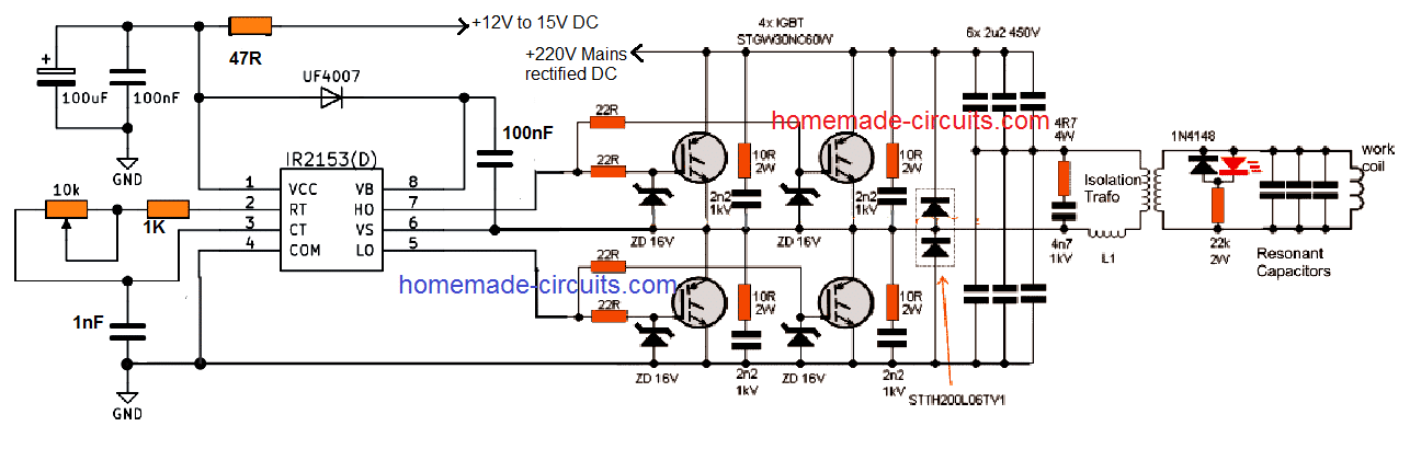
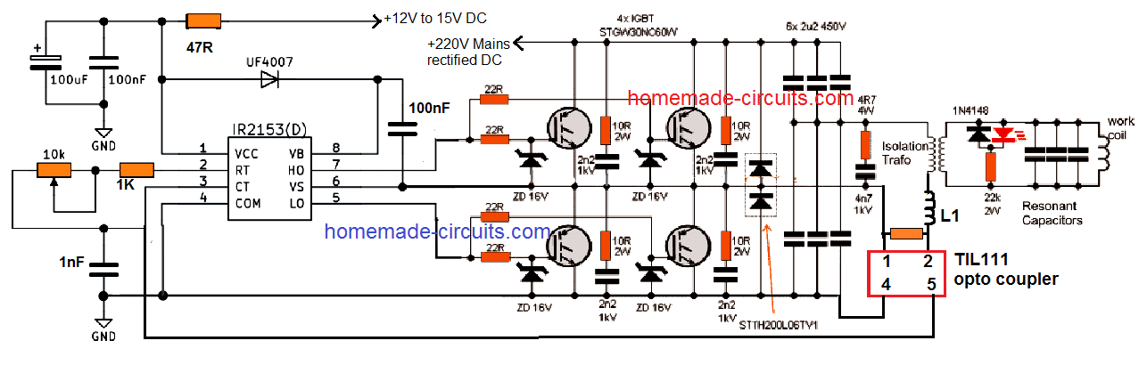
The current flowing through the coil is always much larger than the excitation current. The IR2153 circuit is used to enable the working of the circuit as a “double half-bridge” along with the four controlled IGBT STGW30NC60W.
An equal amount of power is delivered by the double half-bridge as to the full bridge, but the gate driver in the case of the former is simpler.
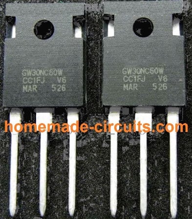
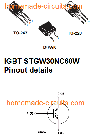
IGBT STGW30NC60W
Using Anti-Parallel Diodes
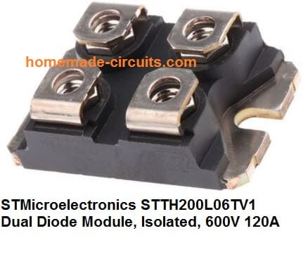
The large sized double diodes STTH200L06TV1 (2x 120A) are used in the form of anti-parallel diodes. Even if the smaller diodes of 30A size will be enough for this.
In case you use the built-in diodes of IGBT such as STGW30NC60WD, then you will not be required to use the smaller diodes or large double diodes. A potentiometer is used in order to tune the operating frequency into resonance.
One of the best indicators of the resonance is the LED’s highest brightness. You can certainly build drivers which are more sophisticated depending on your requirement.
You can also use automatic tuning which is one of the best things to do, which is the course adopted in the professional heaters; but there is one drawback that the simplicity of the circuit will be lost in this process.
You can control the frequency which falls in the range of approximately 110 to 210 kHz. An adapter of little size which can be either transformer type or smps is used to provide 14-15V of auxiliary voltage which is required in the control circuit.
The Isolating Transformer
An isolating transformer and a matching Choke L1 are the electrical equipment which are used to connect the output to the working circuit.
Both these inductors are present in the air-core design.
On one hand where a choke consists of 4 turns on a 23cm diameter, the isolating transformer on the other hand consists of 12 turns on a 14 cm diameter and these turns are made up of double wired cable (as shown in the figure given below).
Even when the output power reaches to a scale of 1600W, you will find that there is still a lot of scope for improvement.
The work coil of the proposed IGBT induction heater is made up of a wire which is 3.3 mm in diameter.
Using Copper for the Coil
A copper wire is considered more suitable to make the work coil as it can be connected easily and effectively to the water cooling.
The coil consists of six turns along with the dimensions of 23 mm height and 24 mm diameter. The coil can get hot in case it is subjected to prolonged operation.
Resonance capacitor is made up of and consists 23 pieces of capacitors of small size which has a total capacity of 2u3. You can also use capacitors of 100nF in the designs such as Class X2 and 275V MKP polypropylene.
You can use them for this purpose even when they are basically not intended or made for such purposes.
The frequency of resonant is 160 kHz. EMI filter is always recommended to be used. A soft start can be used in order to replace the variac.
I would always strongly recommend you to use limiter which is connected in series with the mains such as halogen lamps and heaters of approximately 1 kW when it is being turned on for the first time.
Warning: the induction heating circuit being used is connected to the mains and contains voltage of high level and can be lethal.
In order to avoid any accident due to this you should use a potentiometer which has a plastic shaft. The electromagnetic fields of high frequency are always harmful and can have a damaging effect on the storage media and the electronic devices.
A significant level of electromagnetic interference is caused by the circuit and this in turn can also cause electric shock, fire, or burns.
Every task or process which you carry out is at your own risk and the responsibility will lie with you and I will not be responsible for any kind of harm which comes by in carrying out of this process.
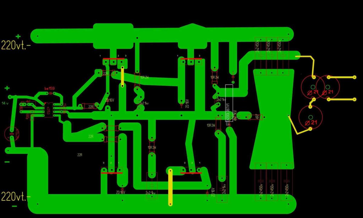
Circuit Diagram
PCB Design
The following PCB design for the above IGBT induction heater circuit was provided by an avid reader of this blog Mr. Атанас.
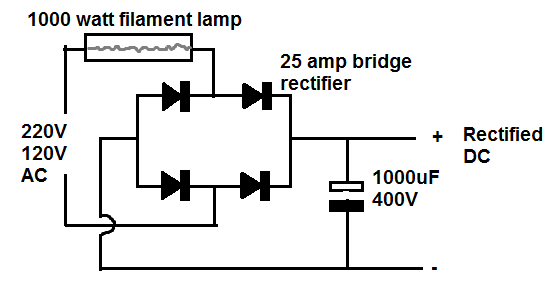
220V AC to 220V DC Bridge Rectifier Circuit with Safety Lamp
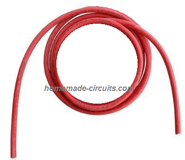
The Choke L1
The design of the choke L1 used in the above full bridge IGBT induction heater circuit can be witnessed in the below given image:
You can make this by coiling 4 turns with 23cm diameter, using any thick single cored cable.
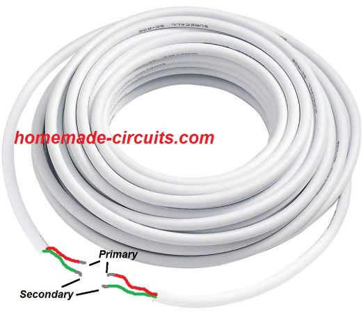
The following image shows the double coiled air cored isolation transformer design:
You can build this by coiling 12 turns with a 14 cm diameter, using any thick doubled wired cable.
The work coil may be build as per the following instruction
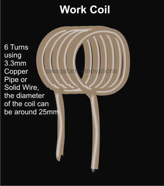
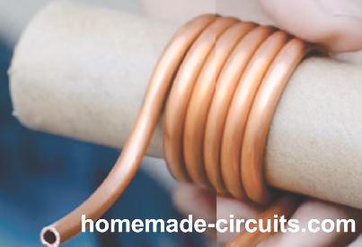
Please note that if the coil is tightly wound then only 5 turns may be required. If six turns are used then you may try stretching the coil slightly for achieving optimal resonance and efficiency.
UPDATE
Adding a Current Limit
The following diagram suggest how a simple current limiting feature can be added to the above explained induction heater design.
TIL111 opto-coupler Pinout Details
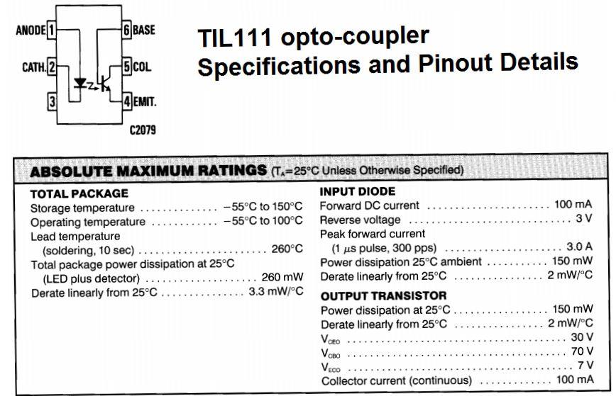
Here the resistor near L1 (let's call it Rx) becomes the current sensing resistor, which develops a small voltage across itself to the desired point when the current begins exceeding the safe limits.
This voltage across Rx is used for triggering the LED inside the attached opto-coupler. The output transistor inside the opto responds to the LED triggering and quickly conducts grounding the Ct, pin#3 of the main driver IC IR2153.
The IC shuts down immediately prohibiting any further rise in current. When this happens the current drops which in turn eliminates the voltage across Rx, thereby switching OFF the opto LED. This reverts the situation towards earlier normal situation, and the IC starts oscillating again. This cycle now repeats rapidly ensuring a constant current consumption for the load, within the predetermined safe limits.
Rx = 2/Current Limit
Feedback from one of the dedicated readers:
Dear Sir- I have successfully made induction heater 1/2 bridge with 4 IGBTs and i want to know that the 1000 watts heater lamp that's been suggested should be permanently connected to the circuit or only upto testing for the 1st time.
Images of the test result are enclosed here under:
Awaiting your reply at the earliest. Regards - Manish.
Solving the Circuit Query
Dear Manish,
While operating the induction heater do you see any glow on the series lamp?
If yes then probably it cannot be removed, if the lamp is in the non-illuminated state and completely "cold" (feel it by holding it) then it can be removed.
Regards
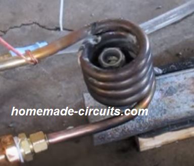
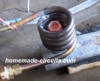
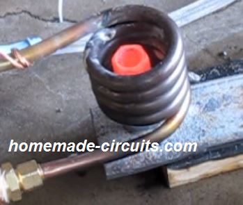
Feedback from Mr. Saeed Mahdavi
Dear Swagatam:
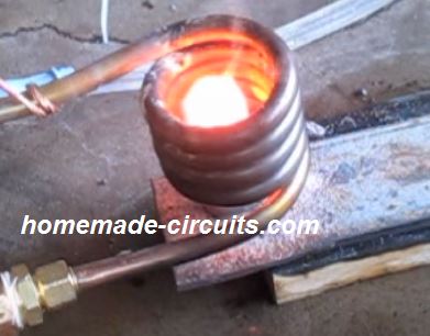
At last I was able to make my circuit work again after a lot of more attempts. And i shot the video with the bolt red hot.
I hope it could be useful for those interested in induction heaters. Would you please tell me how to increase the heat so that the bolt reaches melting point?
The voltage across the mains is 194 volts and the current consumed by the circuit is just 5 amperes and the wave form on the oscilloscope is quite sine waveform.
In my prototype I added a few turns to the RFC choke to get more voltage on the work coil and consume less amp.
The IGBTs worked quite normally without much heating during the operating period. Would you please tell me what I should do to get more and heat. Thanks a lot
Saeed Mahdavi
Video Clip:


Comments
Hi
Is it possible to modify/make a circuit with 27-40 Mhz frequency with 1 KW -to 10 KW circuit for PVC welding purpose ?
Hi,
It may be possible, but then the coil turns may be reduced to just a single turn, which might not heat the the target properly…
Hello, thanks for all the answers
But
i tried out the circuit tiday but i made a wiring mistake(which i have fixed)and my transistors were burned do you think that i can use IGBT STGW30NC60WD transistors instead of the ones recomended. Because i could get these very fast
Hi, sorry to hear that!
The STGW30NC60WD IGBTs are the ones which are mentioned in the above article, so you can use them.
I cannot find any other IGBT recommended in the article?
Please make sure to use a 200 watt series bulb while testing the circuit initially.
If the bulb lights up bright would indicate something is wrong with the circuit.
Assalomu alekum ustoz.
Telegram kanalingiz bormi?
Привет, учитель.
У вас есть канал Telegram или watsap?
Thank you for your answer
I used 1000 w light and it was shining brightly i should have turned it off more quickly
Yes, that’s right!
okey i teied again but 1000w light didnt light up and i thoght something was wrong so i check the transistors but they were ok is there something wrong or can i again try the circuit?
But STGW30NC60WD are not mentioned STGW30NC60W are mentioned i looked at datasheet and there are only small difrrences of when they open between them
Both are identical IGBTs and any one of those can be used, what difference do you see between them?
Gate resistance and gate charge rate are a littel diffrent
Little difference will not matter, so you can use any one of them, whichever is available in your area…
I just used your formula for resonance
160khz,2,3uf
Ok, please show the calculations so that i can check it to see if there are any issues with it…
Hi this are calculations
f = 1 / (2 * pi * sqrt(L * C))
Where:
f = 160000 Hz (resonance frequency)
C = 2.3 uF = 2.3 × 10^(-6) F
L = Inductor value in Henry
Rearrange the formula to solve for L:
L = 1 / ((2 * pi * f)^2 * C)
Substituting the values:
L = 1 / ((2 * 3.1416 * 160000)^2 * (2.3 * 10^(-6)))
L = 1 / (10053096.49^2 * 2.3 * 10^(-6))
L = 1 / (2.322 * 10^9)
L = 4.31 * 10^(-6) H = 4.31 uH
So, the inductor value should be 4.31 uH to achieve 160 kHz resonance using a 2.3 uF capacitor.
hello im sorry for troubling you so much but i just dont seem to get the same number as you i tried many difrent calculator apps and calculating myself and i get indutance of 0,43. i also put the your calculation in photomath just to be sure. Even if i put 4,3 uH and use 2,3 UF that would mean frequency would have to be around 50kHz, and frequency can be controlled only from 110 t0 210khz, so i dont know how this circuit can achive resonance. Is there something I’m missing?
Hi, the calculations which I gave is as per standard formulas, and it looks correct to me, but if you are getting some other values then you can try those values and check the response.
It can be solved only through many practical experimentation.
Thanks for your answer
I checked and measured the coil again with lch meter but the indutanc was wery low araund 1,4uf and i cant get the same value like before of araund 4 uf
Does this mean that the resonant frequency will be diffrent? Or should i change the coil
If you are measuring inductance then value should be in Henries, meaning 1.4uH, or 4uH, not 1.4uF or 4uF.
Yes, if the inductance value changes that will affect the resonance frequency also.
You can increase the number of turns to increase the inductance value.
Hello, i measured the indutance of the coil and its 4,3uH but according to the clculations it shouldbe 430,3uh
Hello, it cannot be 430 uH for sure. The work coil value should be minimal, so 4.3 uH looks more practical.
Please show me the calculations I will check it.
Do you know specific thicknes of the choke for l1 and isolation transformer.
A maximum of 1.5 mm thickness should be enough for the L1 coil core wire.
Hi
do i measure Current Limit or must this be calculated fo rx
Yes, Rx decides the current limit, you can calculate it according to the formula. But I think 2 must be replaced with 1.5, because the opto LED should light up when at least 1.5V is developed across Rx resistor.
Is it important how much amps the auxiliry voltage has?
Which auxiliary winding are you referring to in the diagram?
The 12 v to 15 v
Are you referring to L1?
Im referring to the input voltage that is needed for control circuit
Input voltage to the IC circuit can be between 12 to 15, there is no auxiliary winding in the above design.
If i wanted to turn this into a cooker would i just need to change the wire and its shape or would there be any other changes necesery?
Yes, you just need to modify the work coil to make it flat, by ensuring that the inductance value is not altered.
When im modifying work coil into spiral , can i use the lhc meter and use my own diameter of the wire and number of turns. Im also confused do i measure indutunce with pan on the spiral and power on or with power off and withaut the spiral?
The diameter or the thickness of the wire will decide the maximum current it can transfer and hold.
You can use LHC meter to match the inductance value of the original coil with the modified coil.
You must do this by completely removing the coil out from the circuit board.
Thank you for reply
Im still confused, do i first make the work coil for the heater and measure its indutance and then make spiral with same indutance?
But indutance changes if i add steel pan so how does the circuit keep resonance if the indutance changes.
I wish you a good day
You must first try the circuit and coil specifications exactly as mentioned in the above article.
You are able to make the circuit work successfully, then you can remove the works and modified it as per your requirement by matching the inductance with the original coil.
In the above concept, the coil dimensions and the frequency are selected such that when the coil is magnetized it gets automatically adjusted for developing the resonance.
However a ZVS concept is more efficient as it self adjusts to deliver maximum resonance, and is easy to build.
So I would rather recommend you go for the following ZVS circuit instead of the above one which is quite difficult to optimize.
https://www.homemade-circuits.com/simple-induction-heater-circuit-hot/
good I am an amateur I would like to develop this circuit but I feel that I lack more knowledge about measures you could send me to the mail this circuit with all its values and conetions please I want to undertake myself in this world of electronics and more with induction heating thanks.
Hello Eduardo, I appreciate your interest in this project and I understand that you want to build it, however, the above project is not an easy DIY project and requires prior expertise in the field of induction heaters, therefore this project is not for newcomers, because if you happen to get stuck somewhere, I may not be able to troubleshot it for you, without practically checking your circuit connections, so I would recommend you not to try this project unless you have gained sufficient experience in this field….
Is this avg( american ) or standardised gauge (SWG)?
Hi denis Laporte,
Did you make this circuit if coupd you tell me if it works with your isolation transformer?
There is no point in dealing with the frequency, deal with the beats.
I forgot to mention on the integral that the power supply must be adjustable 9 to 15 volts.
I managed to run the board with a laboratory power supply of 20 volts. There is an error when connecting to the integral, the two terminals must be exchanged. But after 2 minutes I burned the integral, that’s why I soldered the two boards with transformer ferrites 2 double 25 coils at the input and 25 for the output. You need to play a little which cable to connect where matters. 0.6 mm cable
OK, thanks, noted!
OK, thanks for updating the information.
joke, I replaced a 100 k ohm potentiometer and a 10 kilo ohm resistor, the frequency is from 18 khz to 160 khz. One circuit is activated but the other is not, the zener has no voltage
The IGBT looks OK to me, and should work. Just make sure to add a series bulb initially with the input AC and optimize the IC frequency correctly.
I am sending a diagram with corrections, I tried it at 110 volts, so far it has not started, I will try it at 220 volts.
I replaced the transistors with more powerful ones, but I don’t know if they are compatible. SGH80N60UFTU IGBT Transistor 600V, 80A, 195W