In this post I will comprehensively discuss how to build a high power 1000 watt induction heater circuit using IGBTs which are considered to be the most versatile and powerful switching devices, even superior to mosfets.
Induction Heater Working Principle
The principle on which induction heating works is very simple to understand.
A magnetic field of high frequency is produced by the coil present in the induction heater and thus in turn eddy currents are induced over the metal (magnetic) object which is present in the middle of the coil and heats it.
In order to compensate the inductive nature of the coil, a resonance capacity is placed in parallel to the coil.
The resonant frequency is the frequency at which the resonance circuit (also known as coil-capacitor) needs to be driven.
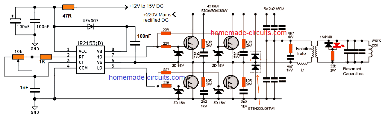
The current flowing through the coil is always much larger than the excitation current. The IR2153 circuit is used to enable the working of the circuit as a “double half-bridge” along with the four controlled IGBT STGW30NC60W.
An equal amount of power is delivered by the double half-bridge as to the full bridge, but the gate driver in the case of the former is simpler.
IGBT STGW30NC60W
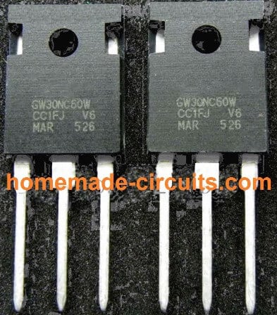
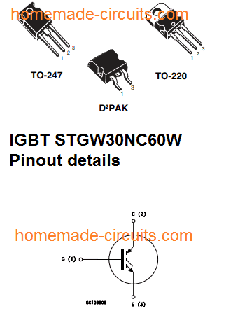
Using Anti-Parallel Diodes
The large sized double diodes STTH200L06TV1 (2x 120A) are used in the form of anti-parallel diodes. Even if the smaller diodes of 30A size will be enough for this.
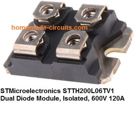
In case you use the built-in diodes of IGBT such as STGW30NC60WD, then you will not be required to use the smaller diodes or large double diodes. A potentiometer is used in order to tune the operating frequency into resonance.
One of the best indicators of the resonance is the LED’s highest brightness. You can certainly build drivers which are more sophisticated depending on your requirement.
You can also use automatic tuning which is one of the best things to do, which is the course adopted in the professional heaters; but there is one drawback that the simplicity of the circuit will be lost in this process.
You can control the frequency which falls in the range of approximately 110 to 210 kHz. An adapter of little size which can be either transformer type or smps is used to provide 14-15V of auxiliary voltage which is required in the control circuit.
The Isolating Transformer
An isolating transformer and a matching Choke L1 are the electrical equipment which are used to connect the output to the working circuit.
Both these inductors are present in the air-core design.
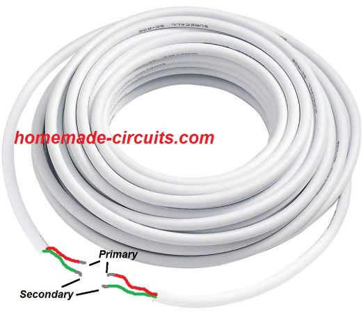
On one hand where a choke consists of 4 turns on a 23cm diameter, the isolating transformer on the other hand consists of 12 turns on a 14 cm diameter and these turns are made up of double wired cable (as shown in the figure given below).
Even when the output power reaches to a scale of 1600W, you will find that there is still a lot of scope for improvement.
The work coil of the proposed IGBT induction heater is made up of a wire which is 3.3 mm in diameter.
Using Copper for the Coil
A copper wire is considered more suitable to make the work coil as it can be connected easily and effectively to the water cooling.
The coil consists of six turns along with the dimensions of 23 mm height and 24 mm diameter. The coil can get hot in case it is subjected to prolonged operation.
Resonance capacitor is made up of and consists 23 pieces of capacitors of small size which has a total capacity of 2u3. You can also use capacitors of 100nF in the designs such as Class X2 and 275V MKP polypropylene.
You can use them for this purpose even when they are basically not intended or made for such purposes.
The frequency of resonant is 160 kHz. EMI filter is always recommended to be used. A soft start can be used in order to replace the variac.
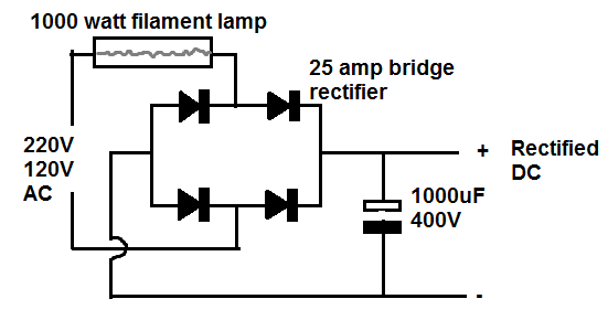
I would always strongly recommend you to use limiter which is connected in series with the mains such as halogen lamps and heaters of approximately 1 kW when it is being turned on for the first time.
Warning: the induction heating circuit being used is connected to the mains and contains voltage of high level and can be lethal.
In order to avoid any accident due to this you should use a potentiometer which has a plastic shaft. The electromagnetic fields of high frequency are always harmful and can have a damaging effect on the storage media and the electronic devices.
A significant level of electromagnetic interference is caused by the circuit and this in turn can also cause electric shock, fire, or burns.
Every task or process which you carry out is at your own risk and the responsibility will lie with you and I will not be responsible for any kind of harm which comes by in carrying out of this process.
Circuit Diagram
PCB Design
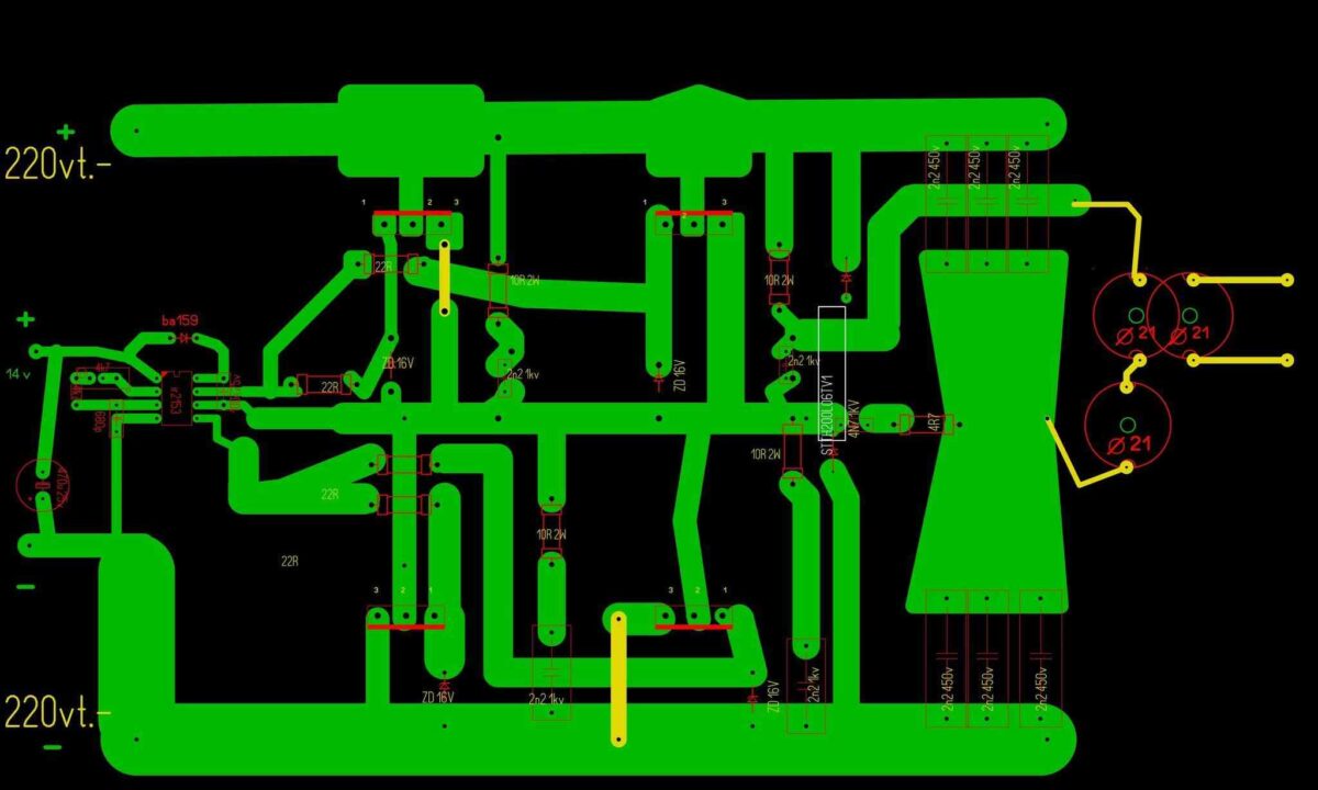
The following PCB design for the above IGBT induction heater circuit was provided by an avid reader of this blog Mr. Атанас.
220V AC to 220V DC Bridge Rectifier Circuit with Safety Lamp
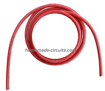
The Choke L1
The design of the choke L1 used in the above full bridge IGBT induction heater circuit can be witnessed in the below given image:
You can make this by coiling 4 turns with 23cm diameter, using any thick single cored cable.
The following image shows the double coiled air cored isolation transformer design:
You can build this by coiling 12 turns with a 14 cm diameter, using any thick doubled wired cable.
The work coil may be build as per the following instruction
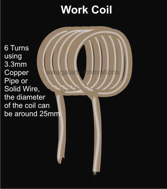
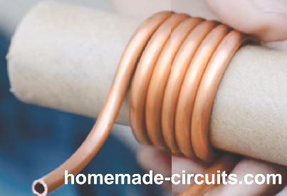
Please note that if the coil is tightly wound then only 5 turns may be required. If six turns are used then you may try stretching the coil slightly for achieving optimal resonance and efficiency.
UPDATE
Adding a Current Limit
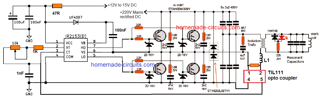
The following diagram suggest how a simple current limiting feature can be added to the above explained induction heater design.
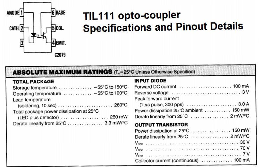
TIL111 opto-coupler Pinout Details
Here the resistor near L1 (let's call it Rx) becomes the current sensing resistor, which develops a small voltage across itself to the desired point when the current begins exceeding the safe limits.
This voltage across Rx is used for triggering the LED inside the attached opto-coupler. The output transistor inside the opto responds to the LED triggering and quickly conducts grounding the Ct, pin#3 of the main driver IC IR2153.
The IC shuts down immediately prohibiting any further rise in current. When this happens the current drops which in turn eliminates the voltage across Rx, thereby switching OFF the opto LED. This reverts the situation towards earlier normal situation, and the IC starts oscillating again. This cycle now repeats rapidly ensuring a constant current consumption for the load, within the predetermined safe limits.
Rx = 2/Current Limit
Feedback from one of the dedicated readers:
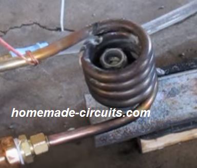
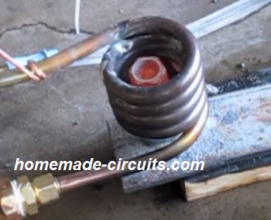
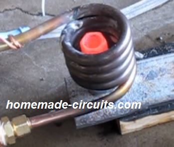
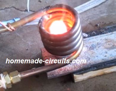
Dear Sir- I have successfully made induction heater 1/2 bridge with 4 IGBTs and i want to know that the 1000 watts heater lamp that's been suggested should be permanently connected to the circuit or only upto testing for the 1st time.
Images of the test result are enclosed here under:
Awaiting your reply at the earliest. Regards - Manish.
Solving the Circuit Query
Dear Manish,
While operating the induction heater do you see any glow on the series lamp?
If yes then probably it cannot be removed, if the lamp is in the non-illuminated state and completely "cold" (feel it by holding it) then it can be removed.
Regards
Feedback from Mr. Saeed Mahdavi
Dear Swagatam:
At last I was able to make my circuit work again after a lot of more attempts. And i shot the video with the bolt red hot.
I hope it could be useful for those interested in induction heaters. Would you please tell me how to increase the heat so that the bolt reaches melting point?
The voltage across the mains is 194 volts and the current consumed by the circuit is just 5 amperes and the wave form on the oscilloscope is quite sine waveform.
In my prototype I added a few turns to the RFC choke to get more voltage on the work coil and consume less amp.
The IGBTs worked quite normally without much heating during the operating period. Would you please tell me what I should do to get more and heat. Thanks a lot
Saeed Mahdavi
Video Clip:


Questions & Answers
Can you publish a circuit automatically controlling a ceiling fan according to room temperature. I mean it should increase / decrease speed according to variation in room temperature.
please refer to this post:
https://www.homemade-circuits.com/2013/01/automatic-temperatureclimate-controlled.html
I am in the process of designing a circuit for analysis purposes and might some some help. Do you consult on electronics matters?
Best Regards
Paul
If it's related to the above induction heater circuit then I am afraid I won't be able to provide much help because I haven't tried it practically yet.
….If it's related to other concepts, within my range, I would surely try to help you out through comments in this blog.
Please tell me can i skip double diodes from above circuit?
STTH200L06TV1
Please see i made changes like this.. is that ok?
https://drive.google.com/file/d/0B3Pn7Yg7DiqkTURzRWxpdm5peE0/edit?usp=sharing
thanks
The diodes are for protecting the IGBTs from coil back emfs, those are compulsory and must be included.
Hello. some help please. Can I apply a single 6.6uF 450V capacitor (one to the top and one to the bottom) in place of 6x 2.2uF? Second, what should be the value of the resonant capacitors?
Thank you.
Hello, a single capacitor will not be able to handle the high current specs of the coil and could burn…therefore many in parallel is recommended.
the work coil resonant capacitors are made by joining 23nos of 0.1uF/400V capacitors in parallel
Please tell me whether there is any relation between the choke L1 and 6 X 2u2 capacitors used, like any resonance or not. What for the choke is used and how it's value selected?
L1 has no relation with the 6 x 2u2 capacitors, L1 is only for limiting current and filtering harmonics.
Please tell me about ferrite core use in L1. There is no ferrite core used in this. Also about the henry reading of L1.
All the inductors are air cored, that is without any core….see the green wire and the white wire coils, those are the inductors.
i am confused about working coil. it is too small. is it enough to heat or melt.
any iron inside the coil diameter will become red hot…
Hello. I have a couple of questions. If I replace the 15V supply by 12V would the controller working properly? And the diode BA519, is it a simple diode or zener? Because the symbol on the schematic confuses.Thank you
hello, 12v would proportionately reduce the output power of the heater (by about 3×20 = 60 watts)
BA159 is a fast switching rectifier diode, it's not a zener diode
Hello. If I use 12V supply instead of 15V will be ok?
please see the above comment….
Hello. About L1 and transformer coils does matter if I place them the one above or inside the other?
No, preferably these must be kept isolated from each other
Hello. I see many that apply the working coil into water for cooling. If i do so, will matter if I apply the transformer coil leads into water too? ( only the leads connected to working coil not all the transformer coil)
I don't think it would cause any problems but make sure the wires are insulated and do not short circuit into the water which could result in a disturbance in the generated frequency and resonance.
Dear sir
What wattage of resistors that 4k7 used at pin 2&3
And also what wattage of resistors that 22r used at pin 5 & 7
Dear Raj, all are 1/4watt except the ones which are specified with their wattage rating.
instead of air core for L1 & isolation transformer one can use ferrite core ? what is mH or uH value of both ?
Nope, ferrite core will not do, it has to be air cored as recommended in the design
uH cannot be measured since it could be very very small in magnitude
instead of air core for L1 & isolation transformer one can use ferrite core ? what is mH or uH value of both ?
Dear sir swagatam
At last I did the sstc based on this schematic sstc4.png – https://docs.google.com/file/d/0B8xT7Q4vaK-bYVRTTnRseHZqb1U/edit?usp=docslist_api
Its worked well for 10minutes with 1inch spark output on secondary coil .but after 2nd start the igbts blow out like crackers suddenly .
I have know idea what went wrong with it .I checked the entire circuit for ani short connections.. But its all well.
Plz suggest any trouble shoot
Thanks
Regards
Raj
Dar Raj, just like mosfets an IGBT can be susceptible to high gate voltages or high load currents and also transient spikes, troubleshooting can be difficult without a lot of practical effort….
try driving the IC with 9V or 12V and use a 200 watt bulb in series with the mains input line while checking, check the response.. how it goes.
makes sure the IGBT gate links with the IC is very close, and not too far away
Dear swagatam sir
Thanks for your valuable suggestions.
Here is one more doubt
What are the symbols are they mentioned at point pin 9 of tl494 and at collector pin of transistor vn 10km ..and also at diode uf4001 points in this image sstc01.gif – https://docs.google.com/file/d/0B8xT7Q4vaK-baUY2Z3U5S2FDNHc/edit?usp=docslist_api
Are they are sine wave symbols or connection by pass symbols
Dear Raj, those are square-wave symbols
sstc02.gif – https://docs.google.com/file/d/0B8xT7Q4vaK-beGpRY1ZwVW5ESG8/edit?usp=docslist_api
In the above image what is mean of 470k 1/2 w 500v.. . as I know 470k 1/2w is a resistor but what about 500v mean ??
2) what is mean of k =0.4 between primary and secondary of coils
Thanks a lot in advance
It may be the voltage rating of the resistor, because normally resistors are designed to tolerate 300V max, you can use two 220K resistors in series in its place
k=0.4mm could be the maximum distance between the winding which should not be exceeded for maintaining optimal performance
Dear sir swagatam
Plz tell me the substitute transistors for
ZTX 450 , ZTX550 and VN10KM MOSFETS for this circuit
sstc01.gif
https://docs.google.com/file/d/0B8xT7Q4vaK-baUY2Z3U5S2FDNHc/edit?usp=docslist_api
Dear Raj,
The closest equivalent seems to be the 2N2222 and 2N2907 transistors, you can try these out.
Dear swagatam
Based on this I have reached to Induction heating but now I am using water cooled copper coil and Want to melt small amount of aluminum inside 30mm inside dia of coil but present circuit is not able to supply more than 1A power so i want circuit with 2kw power and 200khz frequency ..but I don't know how to design that circuit please help me.
Dear Vivek, did you try the above design, it will definitely help you to reach the intended 2 kW power by suitably upgrading the "work coil"
Thank u for your reply .
but the problem is i don't know how to upgrade the present work coil to 2 kw power? please help me to upgrade the present coil…
sir,what is the output range of 25amp bridge rectifier?can you please suggest circuit diagram of 25amp bridge rectifier.
Sarath, if you are asking about the voltage and current handling capacity, the answer could be found in the datasheet of the specific device.
however a 25amp diode could become hot at 20amp current, so a heatsink may be required for it.
BSM 75 GB 120 DLC USED OPTO 3120 PLEASE SAND ME FULL DETAILS AND DROING
my dear such a good contribution thanks in advance for asking a favor quisera see waves resonate to compare circuit because my gives a pure sinusoid and the output of the coil have the same waves thanks
Hello sir, I have made this circuit but even I give the 60 volt to the circuit after 30 second the igbt burnt out…what is the problem? I use buitin antiparallel igbt
sorry abhijit, it will be difficult for me to troubleshoot your circuit from here because I don't know what fault you might have done in circuit connections
Sir, please let me know about the specifications(Strand & Gauge) of L1 coil(Green) and isolating transformer(White) wire..
Arijit, you can use a 3/20 insulated wire for both the coils for max safety
hello sir
sir please let me know about the gauge and strand of the wire used in L1 coil and isolation transformer.
suvradip samaddar