Charging batteries through inductive wireless charging is one of the applications that’s becoming very popular and getting appreciated by the uses. Here we’ll study how to make a wireless Li-Ion battery charger circuit using the same concept. Any electrical system which involves wire networks or cables can be very messy and cumbersome.
Introduction
Today the world is getting hi-tech and the electrical systems are also transiting into better and hassle-free versions for providing more convenience to us. Inductive power transfer is one such interesting concept which facilitates power transfer without the use of wires, or rather wirelessly.
As the name refers to, inductive power transfer is a process through which a certain magnitude of power is transferred from one fixed place to another through the air without using conductors, just as radio signals or cell phone signals are transmitted.
However the concept isn’t that easy as it sounds to be, because with radios and cell phones the transmitted power is merely in few watts and thus becomes quite feasible, but transferring power (wirelessly) so that it can be used for powering high current devices is entirely a different ball game.
Here we are talking about several watts or probably several hundreds of watts that needs to be carried without any dissipation, from point to the other without using wires, an issue difficult to implement.
However researchers are trying their best to find appropriate set ups which may become just suitable for implementing the above concept successfully.
The following points outline the concept, and help us to know how the above procedure actually takes place: Induction as we all know is a process through which electrical power is transferred from one position to the other without incorporating direct connections.
The best example is our regular electrical transformers, where an input AC is applied at one of its windings and an induced power is received at the other winding through magnetic inductions.
However the distance between the two windings inside a transformer is very small and therefore the actions take place very conveniently and efficiently.
When the procedure needs to be implemented at greater distances the task gets a bit complicated. By evaluating the induction concept we find that there are basically two obstacles that make the power transfer difficult and inefficient, especially as the distance between the inducting destinations are increased.
The first hurdle is the frequency and the second hurdle is the generated eddy currents in the winding core. The two parameters are inversely proportionate and therefore are directly dependent on each other.
Another factor that hampers the proceedings, is the winding core material, which in turn directly affects the above two parameters.
By carefully dimensioning these factors in the most efficient way, the distance between the inducting devices can be considerably stretched.
For transferring wireless power in the above discussed method, we firstly require an AC, meaning the power which needs to be transferred must be a pulsating current.
This frequency of the current when applied to a winding generates eddy currents, which are reverse currents opposing the applied current.
Generation of more eddy current means less efficiency and more power loss through core heating. However as the frequency is increased, generation of eddy currents is reduced proportionately.
Also, if a ferrite material is used in place of the conventional iron stampings as the core of the winding helps to further reduce the eddy currents.
Therefore for implanting the above concept in the most efficient way we need to make the source power high in frequency, in the order of many kilohertz and use an input induction system that’s made up of ferrite as the core.
Hopefully, this solves the issue to great extents; at least for the making the proposed project of an inductive charging circuit for Li-ion batteries.
How it Works
WARNING - THE CIRCUIT IS NOT ISOLATED FROM AC MAINS AND SO IS EXTREMELY DANGEROUS IF TOUCHED IN POWERED CONDITION.
This wireless cell phone charger circuit is designed by me, but has not been verified practically, so I would advise the readers to take a note of this.
The circuit can be understood with the following points:
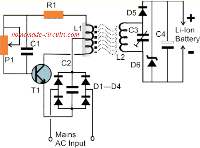
Referring to the figure we see two units, one is the base or the transmitting module and the other one is the receiver module.
As discussed in the above paragraph, the core material of the base winding is a ferrite E-core which is relatively larger in size. The bobbin that’s fitted inside the E-core has a single stage, neatly wound with 100 turns of 24 SWG super enameled copper wire.
A center tap is extracted from the winding from its 50th winding turn. The above coil or transformer is connected to an oscillator circuit consisting of the transistor T1, preset P1 and the corresponding resistor and capacitor.
The preset is used for increasing the frequency through the winding up to optimal levels and needs to be experimented some. A DC voltage is fed to the circuit for initiating the required oscillations, which is derived directly by rectifying and filtering the AC mains.
On applying the DC, the circuit begins oscillating and the oscillations from the inductor being high in frequency escapes into the air to a considerable distance and needs to be grabbed back for the proposed inductive reception.
The receiving unit also incorporates an inductor consisting of air cored 50 turns of 21 SWG super enameled copper wire, which becomes a kind of antenna for anticipating the released power waves from the base circuit.Capacitor C3 is a variable capacitor, the one used in radio for tuning may be tried.
It's used for trimming the reception until the resonating point is reached and L2 gets optimally tuned with the transmitting waves. This instantly raises the output voltage from L2 and becomes optimally suitable for the charging requirements.
D6 and C4 are the rectifying components which finally converts the AC signals into pure DC.
When brought to a considerable proximity, the inductions from the lower base unit is induced inside the receiving coil, the induced frequency is suitably rectified and filtered inside the receiver circuit and is used for charging the connected Li-Ion battery.
An LED could be connected across the output for getting an instant indication of the wireless power transfer intensity at any point of time.
CAUTION: THE ABOVE EXPLAINED WIRELESS LI-ION BATTERY CHARGER CIRCUIT IS BASED ON MY ASSUMPTIONS ONLY;
READERS DISCRETION IS STRICTLY ADVISED WHILE EMPLOYING THE DISCUSSED CONCEPT
AND THE CIRCUIT.
Parts List for the above discussed wireless mobile phone charger circuit
The following parts would be required for making this inductive battery charging circuit:
- R1 = 470 Ohms,
- R2 = 10K, 1Watt,
- C1 = 0.47uF/400V, non polar,
- C2 = 2uF/400V, non polar
C3 = Variable Gang Condenser, - C4 = 10uF/50V,
- D1---D5= 1N4007,
- D6 = Equal to Battery voltage, 1watt
- T1 = UTC BU508 AFIL1 = 100 turns, 25 SWG, center tap, over largest possible ferrite E-coreL2 = 50 piled turns, 20 SWG, 2 inches diameter, air cored


Questions & Answers
Hi GR,
You can use TIP31, but pls be cautioned the circuit has not been tested by me, it's only assumed by me.
….sorry TIP31 will not work, use MJE13005
SIR
How many mah it will give?
Sajjad, it's not a tested design so i am sure about it.
Hello dear, your work is very helpful, if I want more amperage, it is related to the number of turns on L1, right?
Thank you, it is the wire volume that decides the current. To increase volume you must increase the thickness of the wire by winding many thin wires in parallel instead of one or two thick wires
Sir… Im a beginner in electronics with a lot of doubts.. sir what is the point of keeping a rectifer and an oscillator in the same circuit cuz both of them really do the opposite work. rectifier make ac to dc and oscillator oscillates the dc!!.. can u explain why this is done or atleast give me a link so that i can understand this better!! thank you sir
Waiting for ur reply cuz dis is really breaking ma head
Clifford, here we need a high frequency, low current supply for feeding L1 and for achieving the specified results.
The mains voltage has lower frequency, very high current which are just the opposite of what's required.
Therefore we first rectify it to low current DC and then convert it back to AC.
Hello Sir,
Thanks for the circuit! we tried it and it works ! But our problem is it only work at a lower distance, and our teacher required a 6inch distance between transmitter and receiver. our circuit work at a maximum distance of 2inches only. 🙂 Can you help us on what will be the possible solution to our problem?
Thanks sir ! God bless.
Hello heartless girl,
Thanks for trying the above circuit successfully, congrats on that!
for increasing the inductive distance you can try increasing value of C2 value to about 4uF or may be you can replace the input DC by a 12V/1amp smps adapter, this would boost the amps inside the circuit thereby increasing its transmitting capacity.
thanks sir.. actually we just modified the circuit..our input is 220v wee just put a step down transformer 3amp before the bridge .. we also used 3amp diode.. we only get about 4inch distance..
heartless girl, for an optimal response from the circuit you will have to build the whole thing through proper calculations, you may refer to the following pdf for knowing the details:
world-comp.org/p2012/ICW4797.pdf
Hi sir, I have problem on this circuit, can I use this as charger circuit to charge pacemaker device wireless
Hi Sam, yes definitely you an use it for the mentioned purpose! But you may have to modify the parameters accordingly
How can I get a feedback which shows this battery is full when a pacemaker is implanted inside of chest
Sam, I can suggest you but since a pacemaker is a life support system, I cannot take any responsibility for the results or any adverse hidden outcome.
The receiver will continue to draw current from the transmitter as long as the battery is charging, when the current becomes negligibly small or almost zero we can assume the battery to be full charged. This is the basic concept which can be applied, as indicated in the following article:
https://www.homemade-circuits.com/2015/04/battery-current-indicator-circuit.html
hello sir, thanks for the circuit.
my project is to build a inductive charging 12v, 7ah lead acid battery can this circuit help me when is modified?
plz help
Hello Raphael, yes it can be suitably upgraded for the purpose but I have not yet tested it practically so i would be unable to provide you with the required details.
Hi swagatam,
how can we increase the output current at the receiver side.. ?
Hi Bibin, i think it can be done by increasing the frequency of the input and correspondingly tuning the receiver.
Oh.. ok.. Thanks swagatam, let me try and i'll post the result… !
Can the receiving end be modified to use full-wave rectification?
yes it can be, no issues.
it can be any capacitor trimmer which are normally used in FM radios.
Hi, please i just want to know if you have simulated the circuit and if yes which simulation software have you used
Thank you
Hi, No the above design has not been simulated on any software, it's based on my assumptions only.
Hi sir.
please with the D6 can I get the model number , and also the L1 and L2 please what is 25WSG and 25WSG.
Can I get the heartless girl's contact lease.
Hi Richard,
D6 can be rated at the battery's charging voltage spec….although it is not crucial, I would recommend to try the circuit without D6 first and use it only once the basic circuit functioning is confirmed.
25 SWG is the thickness of the wire used in the design.
Sorry I do not have the contact details of "heartless girl".
Thank you sir.
Please what is the voltage and current getting to the transmetter coil… ?
it's 220V/1amp….it can be made by winding 1000+1000 turns on a ferrite core
….using 0.3mm wire
Thank you sir, you have been of great help to us. Thank you.
you are welcome!
Hi, please i want to know the diameter of the transmitter and receiver coils.
Thank you
any ferrite ring that may be capable of accommodating 100 turns will do, use a 100watt lamp in series with input mains to avoid an accidental short circuit and fire….read the caution message before trying it.
sir please this is a link to a circuit diagram i saw on our page ,the name is ( Making a Simple Inverter Circuit) .i will like you to give me the list of component and their values for a 12V solar panel.
https://www.homemade-circuits.com/2012/02/how-to-make-simplest-inverter-circuit.html
sir please help me .
Sir,
here what's the meaning of "e-core" ?
can I use iron-core in there..?
& what's the value of P1 ?
Narottam,
E-core is a ferrite based core over which the copper winding is supposed to be wound.
iron core will not work.
P1 will need to be experimented for getting optimal results.
This is an exteremly difficult circuit, not suitable for new hobbyists…please be informed about this.
Ok..
thanks sir..
I will try to make..
Hi Swagatham
I think, the major reason of a mobile phone battery failure is overcharging. Can you please design an over charge cut off circuit, that can connect between the standard 5v charger and cellphone externely. When the battery reach full charge, phone must disconnect from charger.
Thanks
Hi Anil,
All cell phones have an in-built highly advanced, precision over-charge cut-off circuitry with added capabilities…so an external circuit will be never required.
battery failures could be due to the use of duplicate batteries or sometimes (rarely) due to manufacturing defects.
Well done sir!.the circuit worked with little modifications, was able to transfer power at 10cm apart using 2N3022 .it was amazing! Sir pls at the receiving end can I add up more capacitors to reduce voltage drop during the transfer??.and also my transistor was quite hot but normal???any help with that??
That's commendable Maugost, thanks for updating it. yes you can increase C4 for achieving more improved results.
…add a heatsink with the transistor for making it more efficient.
Sir, I was also wondering if I parallel 2N3022 ,what effect would it have on the circuit, would it increase the frequency of oscillation? Would it increase the signal strength? And also the capacitor c4 what value would you suggest to reduce the voltage drop at the receiving end? Thanks
It will not make any difference, only the wattage handling capacity of the transistor will increase and help to remain cooler….but if the input supply current is additionally increased then probably the range may increase too.
C4 can be any high value capacitor such as a 3300uF,25V or similar
hiiii sir make this circuit but its not works plz help me sir
Hi suneshwar, you can try the following design:
https://www.homemade-circuits.com/2016/02/illuminating-led-using-wireless-power.html
i need ur help sir
Which parameter I supposed to change??, battery volt of pacemaker it can be 2.5v or 3 or 3.7v
The transmitter coil specs and the input power to the transmitter will need to be correctly optimized so that the battery inside the pacemaker does not experience an over-current situation.
By the way How did you plan to attach the receiver stage with the pacemaker?
Hi and thank you for the great post, I am looking to wirelessly charge a 12v lithium battery, my problem is the air gap, it needs to work over a 20-30mm airgap and I am stuggling to find some thing to do it.
the Camera it needs to run uses 12V, 230mA per hour.
Any additional help you can give would be much apprecieted
Thank you
Mina
Hi, thank you.
You can try applying the following design:
https://www.homemade-circuits.com/wireless-cellphone-charger-circuit/
Increase the current input for the transmitter to 2 amps, and check if that allows a 2 to 3 cm distance.
Also make sure the receiver output voltage is slightly lower than the Li-ion battery’s full charge level, check it without any battery connected.
Hi Swagatham
Greetings
Please give me a clarification before I implement your circuit,
I need wireless charging for a 12v,10000 MAh Li-ion batteries which are 10 Meters away from the transmitting circuit
Actually my project is Automate Guided vehicles(AGV’s) which are 10 in number
I want to charge all of them wireless
Please help me with it
Hope you understand me
Waiting for your response
Thanks a lot in advance
Hi Narasimha, it is impossible to create a wireless charger that would efficiently work across a distance of 10 meters.
Hi Swagatham,
This would do a 3.7Vdc LiPo battery correct?
Hi Cameron, yes the circuit will charge a 3.7V Lipo battery also…
Thanks Swagatam,
Would i be able to email you my circuit to see if it will work? Whats the best email i can contact you on? where about are you?
Hi Cameron, you can end it to homemadecircuits
@gmail.com
However we can continue the discussion through this comment platform so that other readers are also able to learn more about the details.
Hi Cameron,
I saw the diagram you sent to my email, yes you can power that circuit through a wireless charger, just make sure the wireless charger output has sufficient current to handle the Li-ion charging optimally.