In this post we will unravel a few homemade crude 220V to 110V converter circuits options which will enable to user the user use it for operating small gadgets with a different voltage specs.
UPDATE:
An SMPS circuit is the recommended option for building this converter, so for an SMPS 220V to 110V converter design you can study this concept.
However if you are interested in easier albeit crude 110V converter versions, you may definitely take a tour across the various designs I have explained below:
Why we Need 220V to 110V Converter
Primarily there are two AC mains voltage levels that are specified by countries across the globe. These are 110V and 220V. The USA works with a 110V AC mains domestic line while European countries and many Asian countries supply a 220V AC to their cities. Folks procuring imported gadgets from a foreign region having a different mains voltage specs find it difficult to operate the equipment with their AC outlets because of the huge difference in the required input levels.
Though there are 220V to 110V converters available for solving the above issue, these are big, cumbersome and immensely costly.
The present article explains s few interesting concepts which can be possibly implemented for making compact, transformerless 220V to 110V converter circuits.
The proposed homemade converters can be customized and dimensioned as per the gadget size so that these may be inserted and accommodated right inside the particular gadget. This feature helps to get rid of the big and bulky converters and helps to keep away from the unnecessary mess.
CAUTION: ALL THE CIRCUITS DISCUSSED HERE HAVE POTENTIALS OF CAUSING SEVERE LIFE AND FIRE HAZARDS, EXTREME CAUTION IS ADVISED WHILE GETTING INVOLVED WITH THESE CIRCUITS.
All these circuit diagram have been developed by me, I have explained how they can be constructed at home and how the circuit functions:
Using Only Series Diodes
The first circuit will convert a 220V AC input to any desired output level from 100V to 220V, however the output will be a DC, so this circuit may be used for operating a foreign equipment which might be employing an AC/DC SMPS input power supply stage. The converter will not work with equipment incorporating a transformer at its input.
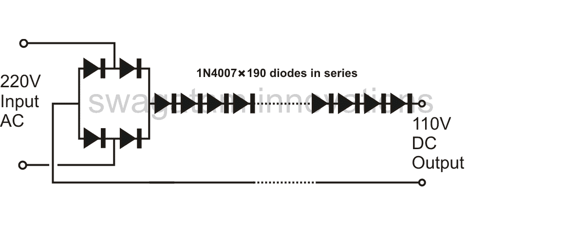
CAUTION: Diodes will dissipate a lot of heat so make sure they are mounted on a suitable heatsink.
As we all know that a normal diode, like a 1N4007 drops 0.6 to 0.7 volts across it, when a DC is applied, means that many diodes put in series would drop the relevant amount of voltage across them.
In the the proposed design, in all 190 1N4007 diodes have been used and put in series for acquiring the desired level of voltage conversion.
If we multiply 190 by 0.6, it gives around 114, so that's pretty close to the required mark of 110V.
However since these diodes require an input DC, four more diodes are wired up as a bridge network for the initially required 220V DC to the circuit.
The maximum current that can be drawn from this converter is not more than 300 mA, or around 30 watts.
Alternatively a simpler version of the circuit can be made, where the main high triac is operated via a cheap light dimmer switch for the intended results.
Using a Triac/Diac Circuit
This light dimmer option presented here has not been tested by me, but looks good to me, however many will find the concept dangerous and very undesirable. It was taken from an old book.
The actual author of this circuit says that he designed the following converter circuit only after doing a thorough research regarding the involved issues and have confirmed it to be safe.
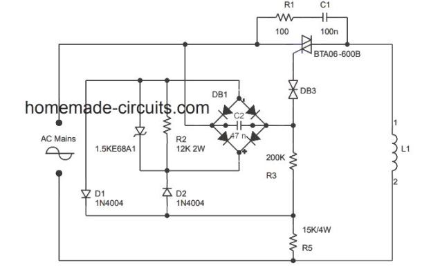
The circuit is based on the regular light dimmer switch circuit principle, where the input phase is chopped at the particular voltage marks of the rising AC sine wave. Thus the circuit can be used for setting the input voltage at the required 100 V level.
The ratio of the resistors R3/R5 in the circuit has been precisely adjusted for obtaining the required 110V at the output terminals across the load L1.
Using Capacitive Power Supply
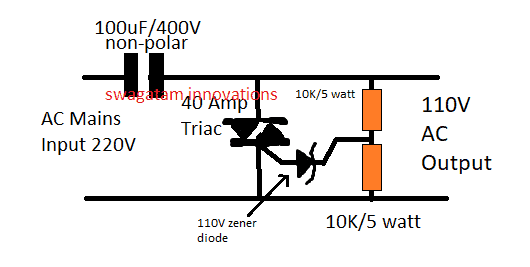
A 100uF / 400V capacitor can be seen introduced in series with the load for extra safety.
The following image suggests how a simple high value capacitor can be used for achieving the intended 220V to 110V output. It is basically a triac crowbar circuit where the triac shunts the extra 110V to ground allowing only 110V to come out across the output side:
Using an Autotransformer Concept
The last circuit in the order is perhaps the safest from the above because it uses the conventional concept of transfering power through magnetic induction, or in other words here we employ the age old autotransformer concept for making the desired 110V converter.
However here we have the freedom of designing the core of the transformer such that it can be stufed inside the particular gadget enclosure which needs to be operated from this converter. There will be always some space in gadgets like an amplifier or other simlar systems, which allows us to measure the free spave inside the gadget and customize the core design.
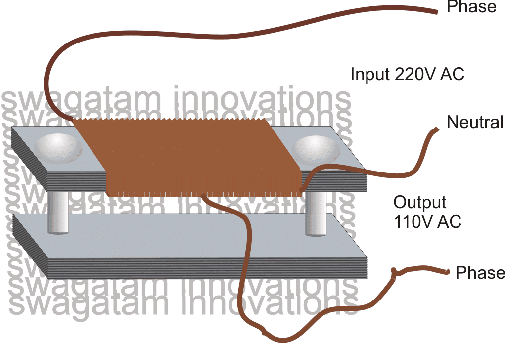
I have shown the use of ordinary steel plates here as the core material which are stacked together and bolted across two of the sets.
The bolting of the two sets of lamination provides some sort of looping effect, generally required for efficient magnetic induction across the core. The winding a single long winding from start to end, as shown in the figure. The center tap from the winding will provide the required approximate 110 V AC output.
Using Triac with Transistors
The next circuit has been taken from an old elektor electronic magazine which describes a neat little circuit for converting 220V mains input to 110V AC. I have explained more about the circuit details.
Circuit Operation
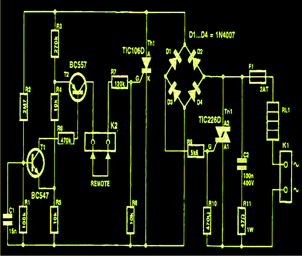
The shown circuit diagram of a transformerless 220v to 110v converter utilizes a triac and a thyristor arrangement for making the circuit successfully work as a 220v to 110v converter.
The right end of the circuit consists of a triac switching configuration where the triac becomes the main switching element.
The resistors and the capacitors around the triac is kept for presenting perfect driving parameters to the triac.
The left section of the diagram shows another switching circuit which is used to control the switching of the right hand side triac and consequently the load.
The transistors at the extreme right of the diagram are simply there to trigger the SCR Th1 at the right moment.
The supply to the entire circuit is applied across the terminals K1, via the load RL1 which is in fact a 110V specified load.
Initially the half wave DC derived through the bridge network compels the triac to conduct the full 220V across the load.
However in the course, the bridge starts getting activated causing an appropriate level of voltage to reach the right hand section of the configuration.
The DC thus generated instantly activates the transistors which in turn activates the SCR Th1.
This causes short circuiting of the bridge output, choking the entire trigger voltage to the triac, which finally ceases to conduct, switching off itself and the entire circuit.
The above situation reverts and restores the original state of the circuit and initiates a fresh cycle and the system repeats, resulting in a controlled voltage across the load and itself.
The transistors configuration components are so selected that the triac is never allowed to reach above the 110V mark thus keeping the load voltage well within the intended limits.
The shown "REMOTE" points must be kept joined normally.
The circuit is recommended for operating resistive loads only, rated at 110V, below 200 watts.
Circuit Diagram
Another Design for Resistive Loads
The design conditions were that this circuit must perform without having specific adjustments, and the price of parts must be low. The apparent specifications of the circuit should be:
- It must detect mains zero crossings
- It must be able to count four mains cycles and switch a triac
- It must include triac to control the load
- It must include a built-in power supply
Beginning with the 4rth requirement, the least expensive power supply could be built using a mains dropper resistor. The reality that the circuit contains floating 'Live' AC is not important here since it doesn't require to be fine-tuned once constructed. Considering that the basic circuit necessities could be completed using CMOS ICs, the current consumption of the design are low.
Triacs typically wouldn't trigger perfectly through a positive trigger voltage and a negative load voltage, thus in order to avoid this issue a negative supply voltage was considered in this 220V to 110V converter circuit. Nothing at all in the circuit depends on analogue voltage ranges, therefore certain amount of ripple on the power supply is not a crucial thing. A Zener in parallel with an electrolytic capacitor helps in regulating the supply.
Power = V2/R = 2202 / 22K = 48400 / 22K = 2.2 watts
Due to the fact we have a diode in series with the resistor, nonetheless, this power is fed only for 50 % of the time, consequently the power wasted through heat is 1.1 watts, that is not way too significant.
The Zener diode ZD1 restricts the voltage negative peaks to -10V, and C1 filters the voltage to some degree. The current output that is obtained from this power supply network is somewhat harder to estimate, although it is feasible!
Circuit Description
Returning back to the explanation, now, the Schmitt trigger NAND gates IC1a and IC1b constitute an cost-effective zero-crossing detector circuit network. During the time the mains voltage is positive, each inputs to IC1b have logic 1 and its output at pin 4 will be as a result logic 0.
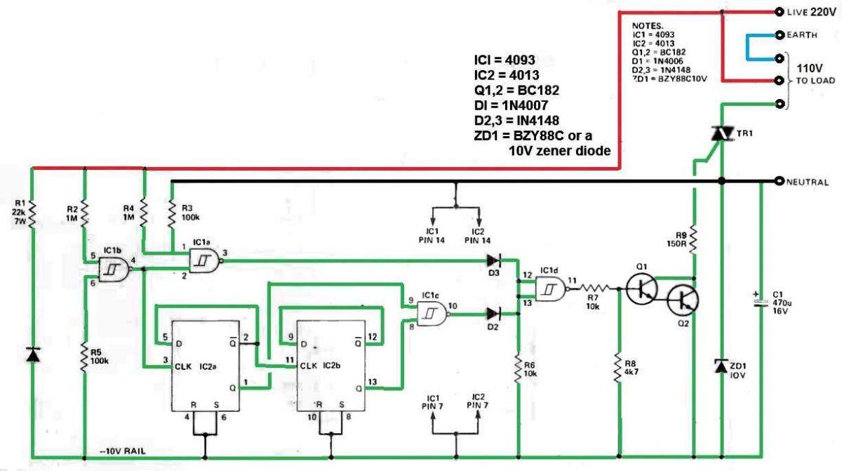
Therefore while pin 2 is at low logic, pin 3 of IC1a could just be logic 1. At this point as the mains voltage deviates down in the direction of zero the voltage drops below the Schmitt limit, which causes the pin 4 of IC1a to turn logic 1.
However since the voltage on pin 1, IC1a, is consistently 10V more positive than the voltage on pins 5 and 6 (since pin 1 is hooked up between Live and Neutral while pins 5 and 6 are connected between Live and the -10V supply line), each inputs to IC1a for some moment of time becomes logic 1 and its output turns logic 0.
The pin 1 voltage subsequently drops under the Schmitt limit very fast, such that, with one input low, IC1a output yet again turns to logic 1.
On the other hand as the mains voltage moves up from the negative peak, the two inputs IC1b both turn low, causing pin 4 to be high. Pin 1, which continues to be 10V more positive, crosses the threshold before pins 5 and 6, causing both inputs to go high briefly, and IC1a output turns low.
Shortly after IC1b turns low, it causes IC1 to return back to a logic 1 output.
The overall impact of the above functioning is to produce small low-going pulses on the IC1a output, that straddle the mains zero-crossing point.
In the meantime, the IC1 pin 3 produces a supply that turns positive right before the negative-going mains zero crossings.
Due to this reason, it could be ideally applied to clock the IC 4013 which is a dual D-type flip-flop, and is employed here to count to four complete mains AC cycles.
Using a D-type flip, the Q output turns into the logic state that was on the D input right before the clock edge, on a positive clock edge. If this logic state is supplied back from the Q output, the D-type switches states on each clock edge.
IC1c decodes the 4013's Q outputs to provide a logic 0 output for one full mains cycle out of four. This is gated together with the mains zero-crossing signal in IC1d; using a couple of diodes and a resistor.
IC1d acts as a NOR gate, allowing the transistors to switch on and activate the triac only at a time when each of the above mentioned voltages are at logic 0.
This is crucial, since if the triggering current was left switched on during the cycle, the required current would surpass the supplied 4.9mA!
This relates to another fascinating point: when a power supply is insufficient, CMOS outputs can perform weird stuff. If the power supply goes below 2V, the 4093 output may flip to logic 1, irrespective of the instructions supplied by its inputs.
If the triggering transistors could turn on under these circumstances, the power supply would never get beyond this voltage, leaving some engineers with mysteriously non-functioning circuitry.
As a result, a 4k7 resistor from the base to the negative supply has been incorporated to stop the transistors from turning on until the logic has sufficient power to function properly!
A sufficient switch ON current must also be given for the triac.
Considering that the Darlington pair of transistors switches on to drop roughly 1V, and that the triac demands a total of 1V to trigger, the trigger current is = 8 / 150 ohms = 53.3mA, which is sufficient for most triac specifications.


Questions & Answers
Hi Swagatham,
How to change a 110V-12V Inverter to a 220V-12V ?
Have any circuit for that ? Or, is it possible to change the winding of the transformer to change to 220V ?
Hi Padma,
You can do it by increasing the no of turns of the 110V winding of the transformer.
Hi Swagatham,
How many Amps solar charge control I have to use for a 500w solar panel system. System config. is 12V – 220V. And also do you have any circuit for making a Solar Charge control ?
Thanks
Hi Padma,
The charge controller specs will depend on the load wattage that you intend to use at the output, if you can specify it, then I can suggest.
I have plenty of these circuits posted in this blog…
I am using 2X150AH Battery with 1800W Inverter. Can I charge the battery with 500W Solar Panel ?? My usage is always below 1000W. For an emergency purpose I am using the 1800W Inverter.
according to me a 500 watt panel would be just sufficient for charging a 300ah battery provided the panel is correctly optimized throughout the day.
Thank you Mr Majumdar. I want to the solar power only at the time of night and maximum usage is 2000 watt hour. Thats why I considered a 500 watts solar panel. And also in future If I want more power I can add some more panels. Am I right ? So please advise me, how many amps charge control I want to use with a 500 w Solar Panel.
Thanks
A 50 amp charge controller would be good enough according to me, you may refer to this post for further assistance:
https://www.homemade-circuits.com/2013/05/how-to-calculate-and-match-solar-panel.html
Hai sir,
By using only diodes converting 230 vac to 110 vdc is it practically working? Is there any heating problems?
Hi sasi, it'll work properly for smaller loads such as LEDs, CFLs etc but not for bigger loads…but this circuit might involve high risks of electric shock and fire.
I don't know if anyone even reads this anymore, but I have a MIG Welder. It was made for 220V. The seller from China put a 110V to 24V transformer to run the PCB. If I take that out & put a 220v to 24v transformer in, would that work. The rest of the circuit is for 230v. I've tried contacting them, but they just give me the run around. II know basic electronics & how to wire 220v. I'm just not completely sure it will work. Thanks ahead of time
yes, that would enable it to work again with a 220V input….
190 diodes in series, what is this debility?
Hi, I have been able to convert 220 to 110 volts very easily and in safe way. I got a bulky Transformer from OLD offline UPS. I connected one AC wire to First common input Tap and second AC wire to Second last Input Tap. Now Use multimeter to probe the AC voltage on different pair of input taps to get desired Voltage (110 or around). I'm using it for Xbox One brought from USA
yes using a transformer or an auto-transformer is the traditional method and the safest way of implementing the conversion…..today SMPS concept is also effectively and much safely used for the same purpose
i have 100v 680watt vertical portable airconditioner which i am running on canadian made hammond autotransformer220/115v 750va.
a.c is rated at 6.8amp and transformer is of 6.2amp which heats up enormously within an hour of operation. can you provide a simple circuit to convert 220v to 110v with better efficiency at that kind of load.
a.c: hafeezcentre.pk/ads_images/1293791840_su57/hc134658675884.jpg
transf: canada.newark.com/hammond/175e-na/step-down-auto-transformer/dp/50H6429
using a conventional iron core transformer is the safest and the most efficient way of achieving the conversion……your trafo might be getting hot due to lower current specs….upgrade the winding with thicker wire and you will find it much cooler
the other efficient and compact method is through an SMPS design which can be hugely complicated..
Hello, I recently moved to US from Europe. My beard trimmer's charger is AC 220v-240v 50/60Hz 3w input and output is AC-3v 100mA.
Is there a way I can make it work on 110v input without changing the output?
If the charger is a SMPS type then you can connect it with 110V without any issues, because SMPS adapters are rated to work from 100V to 285v.
can 110v be converted to 220v?
Hi can u send me the circuit for 230 v ac to both 30v 110 v dc converter circuit in single case
hy swagatam i am searching dc to dc booster circuit about 3kv can you help me???
Hi Sani you can use an IC 555 based flyback converter concept for your application
Hey Swagatam
I have built the this converter using the capacitve power supply in PSPICE. But it is not providing 110V RMS at the output. What changes I need to make in this circuit?
Best Regards
Hey Humaria, please try the second design which I updated just now…and let me know the response!
Please how can I convert one single
12v battery to 24v
using boost converter
Please give me good boost circuit to convert 12v battery to 24v
I do not have a customizable boost converter circuit at this moment with me.
It is an informative blog post about 220V to 110V converter circuit. People who are using
220 to 110 voltage converter would find it useful. Great work!
Hi. I have a single wire 240V feed coming in and I need to install a 115/230V dryer. Is this possible?
Hi Swagatham,
I have an 18V powertools battery charger which i bought in USA it is rated 50watts 110volts. Can i use the capacitive power supply method that you show in this topic? The supply in our country is 220V.
Hi Jun, No I won’t recommend that, you must use an appropriately rated transformer for converting 220V to 110V for your tools.
POWER SUPPLY:
(1)Will 220Vac to a triac with 180 to 20deg variable conduction angle supplying a
110vAC transformer operated / 24vDC, 2amp power supply produce a variable DC supply ?
(2) What is your guess-estimate as to the efficiency and losses in the 50cycle transformer due to the
distorted input waveform?
I know, its a hard question to answer !!
martymarty
Yes you can get a variable DC by phase chopping the primary of the transformer at the specified level, the efficiency should be as per the normal iron core transformer specifications. May be around 80%
Hie Swagatam
I have a Dc supply circuit that uses a 220/110Vac transformer and a full wave bridge rectifier. After the rectification the ripple voltage equals 50Vac and so I need a circuit that can help to filter that ripple voltage to remain with 110Vdc without the Ac element, kindly assist!
Hi Cliff, I guess the ripple peak equals 150 V and not 50V. This is normal and cannot be corrected without a complex circuitry. One way can be to use a light dimmer circuit at the 220V side which may be adjusted until the secondary of the transformer yields 110V DC after rectification.
Hi Mr swagatam, I want to achieve 110v dc after rectification from my step down 220/110v AC transformer. please I need ur help to get this done with specifications.
Thanks
Hi Kamal, you can use the following circuit for your required application:
https://www.homemade-circuits.com/0-300v-variable-voltage-current/
you can remove the 100 watt bulb from the circuit
Dear Mr Swagatham,
you page may be the most useful and believable one around us. Thank you for that.
My question is simple, but i couldn’t find an answer. I have 110 V and 1000 W hot air oven.
So how can I convert our 220 V without any transformer using semiconductors. (1000 W transformer may be very bulky and even expensive).
Thank you,
Gunaratna ( from Sri Lanka)
Thanks K.A. Does your hot air oven work on 110V DC? If yes then it may be possible to go with an electronic solid state based design.
Hello, I brought a 110V 1800W iron from USA. There are many 220v to 110v converters but not with 1800watts. How should I use it. Please help.
Hi, you can use the second circuit from the above article, and try replacing the triac with a BTA41/600
Thanks sir ????????????????????????????????????????????????????????????????
you are welcome!
Please
I like to change some outlets from 230v to 110v
If can please come give estimate
Hello, the best way is to use an 220V to 100V SMPS circuit or simply a transformer….
I used to have a soldering iron with a button to short out a rectifier diode to boost up the temperature from idling mode. I have a 110V toaster, so can I run it off 240V mains by having a diode in series to allow only half the rectified power to reach it in a similar manner to the old soldering iron. The controls are mechanical and not dependent on the mains voltage.
Yes definitely you can do that since an iron toaster is also a resistive load, just like the soldering iron.
Hello Sir Swagatam
Is it a good idea to apply a 12V fan over 190 diodes instead of using heat-sink?
Thank you
Hello Josef, yes fan cooling may be necessary even at 125 degrees Celsius
Hi Swagatam,
I tried the triac based 220Vac to 110Vac exactly, and in addition I put a fuse (5A) at the input. But as soon as I switch on the supply, the fuse is blown. Am I missing anything in this ?
Thanks
Moorthy
Hi Moorthy, did you put a load in place of L1? This circuit was actually taken from an old book, and is not designed by me. However I feel the fuse should not blow if a load is connected at the L1 position.
This is the one with the capacitive power supply not the previous circuit.
It has the 110V Zener and 10k/5W resistances. Can you please check and let me know.
Thanks
Moorthy
OK got it, it is happening due to the triac conducting and shorting the current from the 100uF capacitor which can be significantly high. I would recommend you to replace the 100uF capacitor with a 10uF or any lower value capacitor and check the results. Even with the 10uF the output would have an impressive 500 mA current.
Thanks. Let me check it with a some lower value of the cap.
OK, thanks!
I tried with two 22uF / 250V connected back to back. (Earlier I had put two 220uF / 250V). For few minutes I got the humming like sound from the triac (I think), then the cap that was connected to the source (220V) blew up. Either the current is still very high or I need to use lower cap with higher voltage rating, since the peak go up as high as 350 or so. What are your thoughts on this ?
I think polarized electrolytic capacitors cannot be used for the input capacitors. You can instead try using 8nos or 10nos of non-polar 1uF/400V PPC capacitors in parallel and check the response.
Thank you so much, for sharing electronic experience
I am a freelance electric and mechanical engineer from Indonesia.
You are most welcome, M.Juhri…
Let me know if you have any questions related to the above topic…
Hi Swag!
I bought us Standard Outlets with USB ports and even though the socket is US Standard the required voltage for operation is 220. thanks Temu!
although I have gotten a lot of things that are just fine from there in fact mostly the items I get there are fine but anyway for the capacitive power circuit with the triac would it work backwards? to feed 120 into it?
also just thanks for being a good person in posting all of this at no cost to the user
Thanks so much Roman, I greatly appreciate your kind words!
By “work backwards” do you mean converting 120V to 220V? Sorry, no, that cannot happen, to do this you will specifically require an autotransformer setup, or a dedicated 110V to 220V transformer.
sir i have one solid state rectifier ,that voltage ratings are 415vac to 190vdc, using for hoist breaking , but if 2phase connect supply, but o/p voltage is high 335vdc, rating voltage is 190vdc, i want to know reason with out no filter capacitor.
Sreenivasulu, I did not understand your requirement.
Are you looking for a 415V AC to 190V DC converter?
If yes, what is the output current requirement??
415v to 190v 5amp for hoist break supply
sreenivasuludammu, You will need a transformer for this, without a transformer is not possible…
Hey. Could you help me design a fullbridge DC/DC converter with 325V input, 24V output, I=10A, P=240W?
Hey, do you mean a flyback converter, you can refer to the following post:
https://www.homemade-circuits.com/advanced-smps-flyback-transformer-calculator-for-high-power-converters/