• Skip to main content
  • Skip to primary sidebar

Homemade Circuit Projects

Need circuit help? Post them in the comments! I've answered over 50,000!

Blog | Categories | About | Hire Me | Contact | Calculators-online
You are here: Home / SMPS and Converters / Make this DIY Spot Welding Machine using MOT and IC 555

DIY Circuits | Learn Basics | Arduino Coding

Make this DIY Spot Welding Machine using MOT and IC 555

Last Updated on April 22, 2026 by Swagatam Leave a Comment

Building a spot welding machine at home, it does not really need those complex SMPS circuits or costly stuff, nope. Instead a much simpler way is there, which people use, and it works quite well.

We can use a microwave oven transformer, that MOT, and then add a small timing circuit with it, so now things stay simple, not too much headache, hmm.

This setup, it pushes very high current but at low voltage which is what spot welding needs, so that part matches nicely. Therefore it becomes useful for things like battery tab welding, where strong current pulses are needed but voltage stays low.

How A Spot Welder Works

We see, the idea is simple only, low voltage around 2V to 3V, but current goes very high, hundreds of amps, and pulse is very short, few milliseconds only. So now when this current passes through two electrodes then heat builds at one small point, and metal joins there...

Using A Microwave Transformer (MOT)

That microwave transformer normally takes 230V AC and gives near 2000V AC, but here we do not need that, so we remove that high voltage secondary fully, and then we rewind new one.

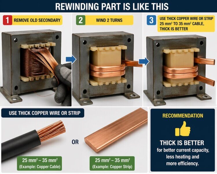
Rewinding part is like this, remove old secondary, then wind 2 turns using thick copper wire or strip, use around 25 mm² to 35 mm² cable, thick is better.

Turns decide voltage, 1 turn gives near 1V to 1.5V, 2 turns gives near 2V to 3V, so now this becomes perfect for spot welding.

Why Low Voltage High Current

We know P = V * I, so since voltage is low then current must go high, that high current is what makes the heat, not voltage, that is the thing here.

How Circuit Works

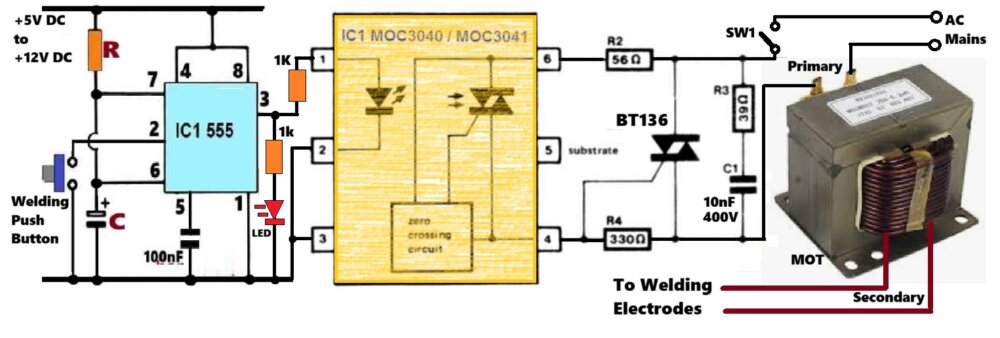
Timer part uses IC 555, standard one, in monostable mode, so when you press push button then output at pin 3 goes HIGH for some fixed time, that time becomes welding time.

Timing comes from R and C, usually we keep it between 10ms to 50ms, small capacitor at pin 5 helps noise stay low.

Then output goes to MOC3041, which gives isolation from AC mains, so control side stays safe.

Then this drives BT136 TRIAC, which is in series with MOT primary, so when TRIAC triggers then AC flows into transformer.

There is also snubber R + C across TRIAC, which helps stop spikes and false trigger, yep important.

Transformer Output

Once power goes in, MOT drops voltage to around 2V to 3V but current shoots up very high, few hundred amps, and that current flows through electrodes and weld happens.

Pulse Control

Timing matters a lot, if pulse is short then weld is weak, if longer then heating too much and damage. so balance is needed.

Thin strip maybe 10ms to 20ms, medium maybe 20ms to 50ms, roughly like that.

About MOC3041

MOC3041 is zero crossing type, so it turns ON near AC zero point which reduces noise and stress, but then timing is not very sharp for very short pulses.

If someone wants more exact timing then non zero crossing type can be used

One MOT can give around 300A to 600A pulse current, which is strong enough for battery tabs, and if cables are thicker and connections tight then performance improves more.

Safety

This involves AC mains and high current, so be careful, use input fuse, keep insulation proper, wiring short and tight, do not touch electrodes when working, and use enclosure.

Conclusion

So now this MOT spot welder is simple, low cost, but very powerful and works well in real use.

Compared to SMPS type, this one is easier to build and gives stable result without too much tuning.

You'll also like:

  • capacitive LED driver with 50 LEDsHow to Design Simple LED Driver Circuits
  • How to Create Air Gap in a Ferrite Core Transformer
  • l4960Adjustable Switching Power Supply Circuit – 50 V, 2.5 Amps
  • How to Design Customized 220V SMPS Circuits

Filed Under: SMPS and Converters

About Swagatam

I am an electronics engineer and doing practical hands-on work from more than 15 years now. Building real circuits, testing them and also making PCB layouts by myself. I really love doing all these things like inventing something new, designing electronics and also helping other people like hobby guys who want to make their own cool circuits at home.

And that is the main reason why I started this website homemade-circuits.com, to share different types of circuit ideas..

If you are having any kind of doubt or question related to circuits then just write down your question in the comment box below, I am like always checking, so I guarantee I will reply you for sure!

Previous Post: « High Voltage, High Current Buck Converter Circuit using Isolated Gate Driver

Reader Interactions

Need Help? Please Leave a Comment! We value your input—Kindly keep it relevant to the above topic! Cancel reply

Your email address will not be published. Required fields are marked *

Primary Sidebar

circuit simulator image

Subscribe to get New Circuits in your Email

Categories

  • Arduino Projects (96)
  • Audio and Amplifier Projects (133)
  • Automation Projects (18)
  • Automobile Electronics (103)
  • Battery Charger Circuits (87)
  • Datasheets and Components (109)
  • Electronics Theory (149)
  • Energy from Magnets (27)
  • Games and Sports Projects (11)
  • Grid and 3-Phase (20)
  • Health related Projects (27)
  • Home Electrical Circuits (13)
  • Indicator Circuits (16)
  • Inverter Circuits (96)
  • Lamps and Lights (159)
  • Meters and Testers (72)
  • Mini Projects (28)
  • Motor Controller (68)
  • Oscillator Circuits (28)
  • Pets and Pests (15)
  • Power Supply Circuits (91)
  • Remote Control Circuits (50)
  • Renewable Energy (12)
  • Security and Alarm (64)
  • Sensors and Detectors (106)
  • SMPS and Converters (39)
  • Solar Controller Circuits (60)
  • Temperature Controllers (43)
  • Timer and Delay Relay (50)
  • Voltage Control and Protection (43)
  • Water Controller (37)
  • Wireless Circuits (31)

Other Links

  • Privacy Policy
  • Cookie Policy
  • Disclaimer
  • Copyright
  • Videos
  • Sitemap

People also Search

555 Circuits | 741 Circuits | LM324 Circuits | LM338 Circuits | 4017 Circuits | Ultrasonic Projects | SMPS Projects | Christmas Projects | MOSFETs | Radio Circuits | Laser Circuits | PIR Projects |

Social Profiles

  • Twitter
  • YouTube
  • Instagram
  • Pinterest
  • My Facebook-Page
  • Stack Exchange
  • Linkedin

Recent Comments

  • Swagatam on Simple Solar Garden Light Circuit – With Automatic Cut Off
  • Swagatam on H-Bridge Sine Wave Inverter Circuit using Arduino
  • Umar on H-Bridge Sine Wave Inverter Circuit using Arduino
  • Duncan on Simple Solar Garden Light Circuit – With Automatic Cut Off
  • Swagatam on Simple Circuits using IC 7400 NAND Gates

© 2026 · Swagatam Innovations