In this post I have explained how to build 4 interesting VU meter circuits, using LEDs and using a moving coil meter.
What is a VU Meter
VU meter or a volume unit meter circuit is a device used for indicating the music volume output from an amplifier or a loudspeaker system. It may be also considered as a device for displaying the PMPO of the amplifier at a particular volume setting.
It is also called music level indicator circuit since the music fed to the circuit is displayed through an incrementing LED bar graph illumination, where the number of LED illuminated is directly proportional to the level of the music volume or music power.
Introduction
Though the unit looks quite technical, which is applied as a measuring device of audio power, in real terms these are more like decorative ornaments of an amplifier.
Without such devices attached, an amplifier system would look quite dull and without any juice.
The varying response from a VU meter certainly gives a whole new dimension to a sound system making it more dynamic with its features.
Prior to the days when LEDs were not so popular, moving coil meter type of displays were commonly incorporated as VU meters and surely these units with there back lights ON produced a distinctive visual effect as their needles deflected from left to right displaying the varying pitch of the connected audio system.
With the advent of the LEDs, the moving coil displays slowly got replaced with the ones which incorporated LEDs.
With color effect at its disposal, LEDs became the HOT favorites as far as VU meter were concerned, even today amplifiers employ a LED VU graph for displaying the music power in an amplifier.
For electronic hobbyists who are rather more interested in building a particular required gagdet right at home instead of buying a commercial piece, this cool VU meter circuit will interest them if they are intending to make one for their music system.
1) 20 LED VU Meter
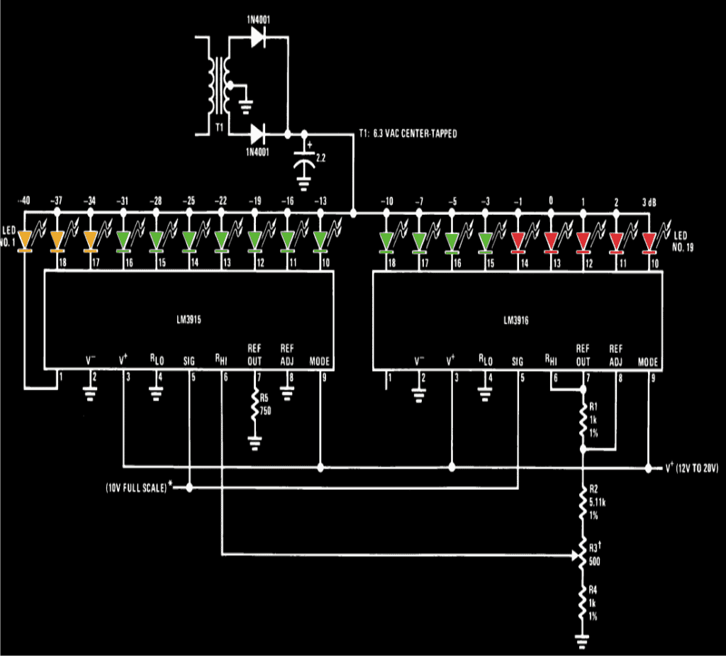
The first circuit of a simple LED VU meter explained here uses the outstanding chip LM3915 from TEXAS Instruments.
The circuit diagram shows a very simple configuration employing two of the above ICs in the cascaded form for producing a good 20 LED sequencing bar type indication.
The music input is applied across pin #5 and ground of the IC. The music input can be directly derived from the speaker terminals of the music system.
R3 has been stationed for adjusting the typical dB levels between the LEDs for enabling visually more enhanced sequencing pattern in response to the fed music input.
The diagram shows a separate power supply being used for the circuit, however if the amplifier supports a 12 volt stabilized power supply, can be used for powering the circuit as well, this would help to get rid of the extra bulk involving the transformer and the associated rectification circuitry.
The color of the LEDs may be selected as indicated in the diagram or may be altered as desired by the user.
Everything is pretty straight forward and can be simply built over a general purpose board.
Assemble the IC first and then go on fixing the rest of the components and connect then to the relevant pin outs of the IC.
The LEDs should be soldered at the end, such that all of them are arranged in a straight line, preferably at the edge of the PCB.
An external enclosure may be used for housing the assembled circuit or possibly the circuit may be installed in the amplifier dashboard itself, if situation permits the required drilling and fittings.
2) 10 LED VU Meter
This easy maximum music level detector VU meter circuit employs 6 LEDs to display six signal levels from -14, -8, -3, 0, +3, and +6dB, or some other quantities keeping the identical spacing.
Approximately 24 mV peak to peak is necessary to be able to illuminate the last 10th LED, thus the circuit is actually highly sensitive and perfectly suitable with any standard product of sound systems.
The circuit is configured around the IC LM3914N bargraph display driver device (IC1), which is wired to drive the attached 10 LEDs.
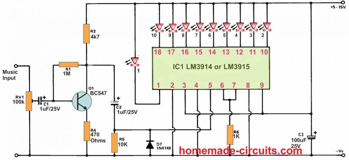
The configuration ensures that with 0.12 V music input only the first LED indicator lights. When the music input rises to 0.24 V the second LED lights up; with a 0.36 V music supply enables three LEDs to light up and so on until an input signal of 1V2 or more is reached which causes all the ten LEDs to be illuminated.
The input signal is applied to a preset for allowing the sensitivity adjustment of the circuit to the appropriate degree. The trimmed audio signal from the preset fed to a low gain common emitter amplifier constructed around the BJT Q1 which enhances a 10 times higher sensitivity for the circuit. Capacitor C2 takes the output signal from Q1 to the input of IC1.
Resistor R5 works like the input bias resistor for IC1, and diode D7 safeguards IC1 from extreme negative input voltage. Resistor R6 controls the current to every single LED and restricts it at around 12 mA.
However, because IC1 can work with only the positive half cycles of the music signal, the LEDs are able to turn on for a only 50% of time. This allows an overall current of 6 mA for each of the LEDs.
The quiescent current consumption of the VU meter is not more than 8mA, which may increase to an utmost maximum of 44 mA while all the 10 LEDs are switched ON.
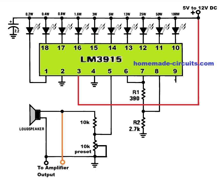
Simplified Circuit
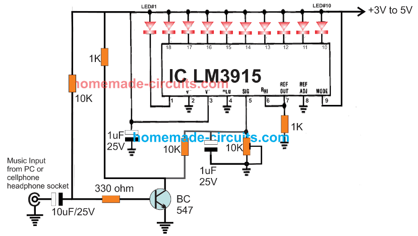
If you are not interested to have a 20 LED VU meter circuit rather satisfied with a 10 LED VU meter, then the following design using LM3915 can be very handy.
3) VU Meter using DC Voltmeter
The below given 3rd VU meter circuit will also show the music level but will indicate it through an ordinary moving coil voltmeter, as shown in the following diagram.
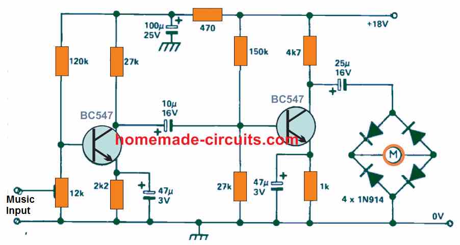
The VU meter circuit indicated in the above diagram consists of a 2-stage voltage amplifier which operates a connected a level meter. The inpu music AC signal is first amplified, and then rectified, and finally the resulting DC potential equivalent to the music level is displayed on the connected voltmeter.
The VU circuit using a voltmeter can be used with any amplifier, music system, audio mixer etc and must be connected from an early stage of the pre-amp. The current intake of the circuit in the absence of an input signal is around 2.8mA. The 12K preset can be used for adjusting the sensitivity of the circuit.
The meter M can be any general purpose moving coil voltmeter.
4) Non-Contact VU Meter
The following circuit shows the 4rth design. This 10 LED VU meter yet again uses the versatile LM3914 or LM3915 sequential LED driver for detecting and driving 10 sequential LEDs in dot mode or in bar graph mode which can be selected using the switch S1.
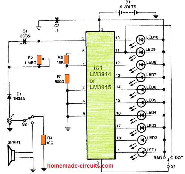
The best feature of this VU meter is that, it can be used to indicate the music levels either by directly connecting the line output of the amplifier with the J1 socket, or it can be operated without any direct connection, meaning without using physical wires for the connection.
How the wireless mode can be implemented?
It can be done through the small 8 Ohm speaker, which simply needs to kept near the amplifier loudspeaker. When the music from the loudspeaker hits the VU meter speaker SPKR1, it converts the music into tiny electrical pulses which is sensed by the LM3914 IC and appropriately converted into a sequential up/down LED movement, depending on the strength of the music from the amplifier loudspeaker.
Switch S2 can be used for selecting the direct connection mode or the wireless speaker mode.
S1 is used for enabling the LEDs to run and imitate a dot, or like a bar moving and down.
Stereo LED Music Level Indicator Circuit
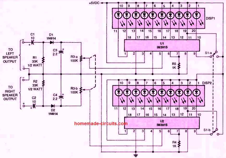
The circuit is composed of two LM3915 drivers for dot and bar displays. Due to the fact the voltage dividers, the voltage reference, and the adjustment inputs are all located within a single integrated circuit, which considerably lowers the number of components.
By cascading the LM3915s, the circuit may be extended to 20 or more sections.
In this prototype, I utilized tri-colored bargraph displays, but you can also use any color scheme for the individual LEDs or a simple 10-segment bargraph display. For the adjustment control, I additionally utilized a 100k stereo potentiometer (R3).
This prevents the need for two different adjustments and guarantees that both sides might still get an identical signal. Switch S1 alternates between dot and bar modes.
I'm not precisely sure how much power this circuit can handle; it was designed mainly for smaller stereos.
While in barmode and operating at full scale, the circuit uses about 300 mA.
You may use batteries, your own power supply, or even the supply from your stereo to power the meters, like I did. I'm hoping that anyone who had the same issues as me would find my circuit to be both intriguing and practical.


Questions & Answers
lebih mudah dipahami lagi, menggunakan gambar dan desainnya agar terlihat lebih jelas… agar orang awam yg baru belajar elektronik mengerti… terimakasih 👍
Hi swagatam ,
I’m new to electronics trying to learn.
I’m interested building one of your circuit using IC LM3915 driver for
dots and bars . If you can please send me the complete parts list and
explanations. I really appreciate it
Thank you
Hi Joel,
I will try to help you and make sure you succeed with this project.
If you can take the audio input supply from the speaker terminals then you can use the following design:
For dot mode just keep the pin#9 unconnected, and for bar mode connect pin#9 with the positive supply.
All the resistors shown are 1/4 watt CFR, preset can be any standard 10k preset, LEDs are 3.3V, 20mA, 5mm type, the capacitor is 2.2uF 25V.
The supply DC can be anything between 5V and 12V DC.
If you have any specific questions or doubts, please let me know I will try to solve it for you…
Hello sir, I hv assembled the second vu circuit using lm3914 and bc 547 transistor. This was intended to use along with a bluetooth amplifier module.(usb type along with PAM 8403 amp) And I looked to power the bluetooth amplifier and the vu with the same power of 5v.I connected the input to the vu from one of the stereo speakers.But when the vu circuit’s power ground is connected to the bluetooth amplifier’s supply ground, things are going worst. The power supply voltage and current goes highly erratic and causes about 1.5 amp current to flow in the power supply. Then I just pulled off the vu ground and just kept it unconnected. Then the behaviour is normal. Is it that some connection I hv done wrong. Also sir, will it be an issue if I swap the vu meters audio input wires from the speaker. My guess is that the vu circuit’s ground point is being completed through the speaker negative. Please give the correct method for connecting the vu audio signals from amplifier. if connection is ok then what causes the problem. I hv tested so many times and with different power supplies but yielding same result
Hello Binoj,
Joining the grounds of the LM3915 circuit and the amplifier circuit is definitely recommended, so i am not sure why it is causing any issues.
Actually, if you don’t join the grounds of the two circuits together then the output results may not be accurate.
However, the BC547 stage is not required if you are connecting the LM3915 input directly to the speaker terminals.
So, please try the following design, and check the response, and yes, the grounds of your amplifier and the VU meter must me connected together.
Please check it and let us now:
Do you sell screen printed pcb boards? If not can you send me the pdf for number 4 of the wireless led vu meter? Also do you have a pdf for a 10 led vu meter using the LM 741 with the LM3915? It’s suppose to be a preamp power level indicate audio level indicator vu meter
Sorry, we don’t have the PCB designs for the above projects. We also don’t have the 741 based VU meter circuit with us at this time.
Hi Sir,
I want to drive around 1 meter led strip of 12 volt on vu meter. I think may be possible through BC557 transistor. Can you make a diagram.
Hi Ram
You can add the following driver stage to all the output pins of the LM3915
The transistor can be a BC557 if the LED strip current is below 50 mA
Hello Sir,
I would like to know how to connect some RGB SMD LED strips (9 LEDs per strip; 3 colours each) to the output of LM3915. Can I use a PNP transistor (BC557 or 2N3906) for that circuit for each output?
What will be the current flow to the LEDs? From datasheets, I found BC557 has 100mA and 2N3906 has 200mA at its max. If the load (LEDs) needs more current than this limit, will the transistor gets gamage/explode?
I was planning to power the whole with a 12V 2A DC adapter.
Hello Arjun, yes you will have to use PNP transistors at the outputs of the LM3915 IC.
You can initially try 2N2907, if you find it is heating up, then you can go for BD140 transistor
Thank you so much sir.
Each LED may be of 20mA, I thought so.
So, 9 LED means 180mA.
Will 2N3906 be sufficient for this 9 LEDs?
If I need to power 18 LEDs, there will be a load of 360mA, and for 27 LEDs, there will be a load of 540mA.
2N3907 has its maximum current of 600mA
Is that Okay for 27 LEDs?
Can I power the circuit with 12V 2A, if the transistor used is 2N3906 with just 9 LEDs (180mA)?
Will there be any problem with transistor or LM3915 IC???
Hello Arjun, you will need one transistor each for each LED on each channel. For 20 mA current on each transistor, BC557 will be enough.
For over 100 mA on each channel, you can use 2N3906,
For over 200 mA, you can use 2N2907
and for over 300 mA, you can use BD140 and so on.
…..for 20 mA on each channel, 2N3906 or BC557 will be fine.
12V 2 amp power supply will be OK, but each LED on each transistor must have a 1k series resistor, this will ensure a safe operation for the LEDs and the LM3915 IC both….
Sir,
Could you please check the whole circuit of LM3915 whether it’s really good or bad?
Do I need any modifications here?
http://3.bp.blogspot.com/-1_XXdG3XhUE/VRd5SL4M2mI/AAAAAAAAAOo/o2aMv7MPoB8/s1600/38mnn6%2Bdiag.TIF
Arjun, the LEDs must have a series resistor of 1K each, otherwise they will burn immediately. Rest all is fine….
Thank you Sir. ????????
Hello Sir,
LM3914 IC is costly; i.e. Rs.75/- per piece.
Is it possible to create VU meter using Transistors ?
My main motive is to keep the cost low.
Many thanks for your help
Regards,
Nameer Mallick
Hi Nameer, you can customize the concepts presented in this article:
https://www.homemade-circuits.com/led-music-level-indicator-light-circuit/
Thank You… 🙂
Good morning sir,
Thank you very much.
Let me try it….. 🙂 🙂 🙂
Have a nice day……
With regards,
K.Kausik
you are welcome kaushik…
THANK YOU,SIR.
It doesn't matter,how the dual effect is occurring.
My only problem is that,I want to connect large number of led in different segment.
I've found out a circuit that connects with a resistance from lm3915 pin out to the base of a npn transistor and another resistance from base to the supply of the led. NPN collector to supply and emitter to led. Thus I can connect a large number of led in different segment by choosing a proper transistor.
I don't know if the circuit is correct or not but I have tried with different values of resistance still not succeed.
Any guidance……
Thanking you,
With regards,
K.Kausik
OK understood, but NPN will not work here, you will need PNP transistors at the outputs of the IC.
You can try BD140 or 8550, or 2N2907 and these will allow to connect many LEDs between their collectors and the ground line…..the emitters will need to be connected with the supply lead.
the base resistor value will depend on the LED current rating.
also the LEDs connected with the collector will require their own limiting resistors…and these resistor values could be adjusted to get the desired dim or bright effect on the LEDs.
Sir,
Firstly I would like to thank you for your quick response 🙂
For my thunder and lightning project I've collected some thunder sound effect through net. I will play the sound effect and wish to connect a VU meter(or something like that) input from amplifier output terminal. As a result I want a dim flash for low sound and heavy flash for high sound. I intend to achieve this by connecting a less number of led and huge number of led(may be coloured) through the different pin out of lm3915. I've a 12v power supply.
And that's all……
Thanking you,
With regards,
K. Kausik
thanks kikira, but what about the sound effect, should it be simultaneously heard with the lightening or a little later after the LeD flashing…to simulate a real lightening sound delay effect…
by the way you can still try the above circuit, and feed the music at the shown input terminals for getting the results…
you can connect LEDs with higher resistance value with the first IC, and lower value with the subsequent IC, this arrangement will allow the first IC to illuminate the LeDs with lower intensity in response to lower sound volume, and the second IC will illuminate the LEDs with brighter intensity in response to higher sound volumes.
I'll try to produce it soon possibly..
Still I'm eagerly waiting for your kind presentation……..
Thanking you,
K. Kausik
I'll do it soon,
also let me know how do you intend to initiate the effect…meaning what do you prefer as the input trigger source??
is it only a power ON that should switch ON the lightning effect or some other preference?
and after how many seconds the sound should be initiated??
Good morning sir,
It's only a lightning simulator. I just wish to flash led's with sound.
Thanking you,
k Kausik
OK thanks, I will ry to post as a new article soon….
Good morning sir,
Thanks for your quick response…but my problem is little bit different.
Actually I want to create thunder and lightning effect in a small room. Complete scientifically. Lightning first and sound. So I can't use sound activated relay.
Actually calculating the current is quite difficult to me.
Any suggestion ….
Thanking you,
With regards,
k.Kausik
Kaushik, it is not clear what exactly what you intend to build, is it only a lightening simulator or sensing actual lightening and then displaying it through LEDs? Please clarify….
Sir,
I have made this circuit with lm3915 successfully. Now I wish to replace single led with a number of led's for each output using bd139 or something like that.
If it is possible, I need your help with a hearty gratefulness.
Thanking you,
k.Kausik
kaushik,
you can simply use a 24V supply for the circuit which would allow you to connect at least 8 LEDs in series across each of the channels….but the LED current cannot be more than 20mA
Yes 9V is common for IC and all LED's.
The schematic I sent does work as desired (albeit needing resistors for "current" led and switch as you suggested) but just doesn't keep the "max" LED lit long enough. Here's a link to my breadboard layout if you are still skeptical: https://drive.google.com/file/d/0B37pDhLa1w2lNDdUeFRIVk9XdEE/edit?usp=sharing
I modified the circuit as you recommended in your schematic, and it also works as desired, but has the same issue of not keeping the "max" LED lit long enough (~1min with the 100uF cap to ~3min with a 470uF).
Any thoughts to improve? Ideally the "max" LED could stay well lit up to an hour.
If you measure the voltage at the collector of the PNP after disconnecting it from the base of the NPN you would find the entire 9V present here.
The base of the NPN is actually sinking the entire 9V to ground and allowing only 0.7V to be measured at its base since its the regular forward drop rating of all BJTs. If you are not connecting a resistor at its base you are forcing it to work under stress, reducing its life span…. the10M may be not allowing too much current , but without a base resistor the NPN is always in an unsafe zone.
Alternatively to avoid the base resistor you could simply shift the LED/resistor assembly across emitter.ground of the NPN, and connect its collector directly with positive.
I originally had a res protecting the NPN base but noticed that the voltage coming of the PNP collector was so low (~.7V) I that I might get away without it. I believe the 10M is just barely letting the PNP open so in a way protecting the NPN as well…
Your are correct that I need diodes at each junction leading back to the switch (I only had two "max" leds breadboarded and one was hooked up with a corroded wire which I believe only by chance allowed my most recent schematic to work)
I will try replacing the 386 with a BJT as referenced but I believe I am already at the lowest possible senstivity (with pin 8 to gnd) for the 3914…
Now that I think about it the 3915 and 3916 would likely perform even worse since they are effectively "less sensitive" to signal inputs than the 3914.
The design looks fine to me, however without a resistor at the base of the NPN transistor would instantly fry it, I am surprised how it worked for you.
Also, in order to work with a single reset switch you have shorted all the 10M inputs together, that would mean as soon as one of the inputs of the IC becomes low all the LEDs would light up together….are you sure you have confirmed it practically??? All the 10M points needs to be terminated via individual diodes to the reset switch for implementing this correctly.
The LM386 stage could be replaced by a single BJT stage as given in the following article (at the bottom) and the REF of the IC could be varied for tweaking the sensitivity.
https://www.homemade-circuits.com/2012/03/how-to-make-vibration-detectormeter.html
To me all the versions are almost identical with their specs, it won't make much of a difference.
Another NPN seems to do the trick quite well (1hr+ as laid out in link below) so I don't think I'll need to add another IC. I'm sure this schematic is far from "technically sound" but it does seem to get the job done with minimal parts:
https://drive.google.com/file/d/0B37pDhLa1w2laFctUVJXQ0FlLVU/edit?usp=sharing
I only modeled two of the "max" leds to show how that I am using a common switch to reset all of them at once.
The only problem I'm having is that the output from my 386 (looks like saturating at +/-1.4V on my oscilloscope) isn't enough to activate the full row of LED's. I grounded pin 8 on the 3914 to set the "Ref Out" to 1.25V. I'm confused because when I use a DC power supply directly into pin 5 of the 3914 and sweep from 0-1.25V the LED's light up perfectly.
I'm thinking I might need to try the 3915 or 3916 (and/or a better amp) but don't have any on hand so wanted to run this by you before ordering… (i'm not sure why they show a slightly different "typical application" for the 3914, i'm hoping they can be swapped without issue?)
Also I tried taking out the resistors protecting the switch and each current LED (again trying to limit components) and did not notice any significant increase in power consumption so I left them out… (currently pulling ~70mA with all LEDs on)
Thanks again,
Keith
….for achieving delays in hours you could probably opt for 4060 ICs on each pinout of the IC 3914, the entire design could look enormous but nevertheless will provide you with all the desired delay effects.
agreed! your circuit may be working but its not technically correct, the one that I have suggested is technically sound,
anyway a delay of 1 to 3 min looks quite large, and perhaps cannot be achieved using a single transistor, you will probably need another NPN stage with the existing PNP.
Alternatively you could consider using NOT gates from the IC 4049 (each has 6 nos, so two ICs would be required) for achieving the 1 to 3 minutes or even upto 10 minutes using much smaller capacitors.
Here is the link just in case:
https://drive.google.com/file/d/0BwBqyM2fjd9-akJPU1ctd1p2Z3M/edit?usp=sharing
The schematic has many faults, let me clarify them point wise:
I am assuming the 9V supply to be common with the IC also, and this is recommended for simplifying the operations.
Connecting the cap across the emitter/base of the transistor will definitely keep the max LED illuminated for sometime, however this would also produce a delayed illumination when switched ON, therefore it's not the right place for the cap to be in.
Are you using simulator for checking the results? I am afraid in that case you may be getting misleading results from it, that's why I never use simulators.
with a 9V supply the "current LEd" must have its own limiting resistor, a 10K would be OK in series with it, otherwise the IC could dissipate a lot and get warm.
The present positioning of C1 is correct, except its polarity which needs to reversed.
The reset button must also accompany a limiting resistor for ensuring better safety to the IC
I will try to update the corrected diagram soon in the above article.
It looks like they are using the thin line as positive on their electrolytic capacitor schematic symbol, and yes C1 is to keep the transistor on for illuminating the "max" LED. I tried it directly in parallel (no resistor?) with the "max" LED as well as between the base/emitter but neither kept the "max" LED lit…
Your question about the polarity of C1 prompted me to try my pushbutton switch to 9V instead of ground which works perfectly (although I don't understand how exactly)
Only problem now is that with the 100uF cap and 100k res the "max" LED only stays well lit for about a minute as it slowly fades. I have tried various cap/res combos for slightly improved times (max ~5 min) but like you said the high res compromises how bright the led gets. Also I would like to limit the cap to 100uF for space considerations if possible…
Here's an updated schematic:
https://drive.google.com/file/d/0B37pDhLa1w2ldXRLcVhDcXlJSlk/edit?usp=sharing
Thanks Kieth, that looks great, however I could not relate the positioning and the polarity of C1. Is it for sustaining the illumination on the "max" LED? If it is so then I think C1 must be connected directly in parallel with the "max" LED or simply across the transistor's base/emitter.
Rest everything seems to be correct with the circuit, the base resistor of the transistor could be lowered a bit for increasing the LED brightness, a 33k would probably work better.
I am assuming the bat 9V being used for the entire circuit otherwise its negative will need to be made common with the ICs negative supply.
I shared the schematic with you through google+.
Swagatam,
First let me thank you for creating this terrific site, it is an amazing resource for students, hobbyists, and professionals alike. I am a high school electronics teacher (with an ME background so I've been learning on the fly) and often find myself stumped on more advanced circuits.
I am trying to build a visual sound meter that will show both the "current volume" level (via led bar) and the "max volume" (another led bar w/ pushbutton switch to reset)
So far (sorry no schematic just on a breadboard) I have an electret mic feeding a 386 audio amp then into a LM3914. The "current volume" display works fine although I would like to broaden the volume range that it reacts to (perhaps even add another mic and average the inputs so it's not so range dependent).
I have gotten my max volume display to work but in a very sloppy manner and I am hoping you have a better suggestion. Right now I'm using a relay to trigger a transistor/capacitor/resistor combo for each led on the "max volume" display (which does keep them lit but is just a lot of components). I wanted to a trigger those relays with another transistor activated by the 3914 output but couldn't get it to work (may not have been biasing the transistor correctly) and have resorted to using a photoresistor to activate the transistor which then triggers the relay.
Not a high priority project but just a something cool for the classroom. Hopefully you have time to give it a look.
Thanks!
-Keith
I am trying to understand it but could do only partially, I think a schematic would help to make the whole picture clear and for making required corrections.
By the way which capacitor are you referring to and in which diagram?, if you could identify the exact component I would suggest a suitable solution.
Actually I have never used a schematic or PCB designing software so far, presently I rely on corelDRAW for making these drawings….so not very sure which one could be the best, I'll do some research and let you know for sure, though
Regards.
Definitely don't need relays that was just me doing things the hard way. To clarify I want the "max volume" led's to light up along with the first led bar set but STAY ON until a pushbutton switch is pressed.
I created a partial schematic (single output from the 3914) showing my new setup. I will try to link as instructed below. On a side note do you have suggestions for hobbyist level circuit design software with pcb layout capability? I've tried a few (currently using DesignSpark) but haven't found anything I really like.
Anyway everything works fine with a single pnp except I can't manually reset my "max volume" led (have to wait until the capacitor drains for it to turn off). I thought I could just short circuit the capacitor leads (where the pushbutton switch would go) but it seems to just recharge the cap through the "current volume" led. I'm pretty sure I could use another transistor to solve the problem but would like to use as few components as possible (will be put on pcb).
Any advice would be appreciated.
Thanks again!
Thank you so much Kieth,
In order to get correct biasing from a 3914 you will need PNP BJTs configured, you may take the help of the design posted in the following link:
https://www.homemade-circuits.com/2013/07/bike-generator-to-220v-converter-circuit.html
Although the IC has in-built resistors for each of the outputs, attaching external 1K resistors with the bases would be safer and therefore is recommended.
However I couldn't exactly understand the utility of the max volume" feature, does it refer to the actual volume content from the amp output?
And why do we need relays for this? Since LEDs are used, these can be lit using transistors directly….
Regards.