A simple LED torch circuit that would light up 3 white LEDs from a 6 volt supply and would make your battery last forever is described here.
A useful voltage doubler circuit is incorporated here to make a highly efficient circuit using just a handful of components.
Introduction
Learn more how to build it. White LEDs are quite renowned for producing dazzling lights at very low currents.
But, if they are not configured cleverly can in fact be pretty poor in the above respect. Learn the simple trick to optimize and make a highly efficient LED torch at home.
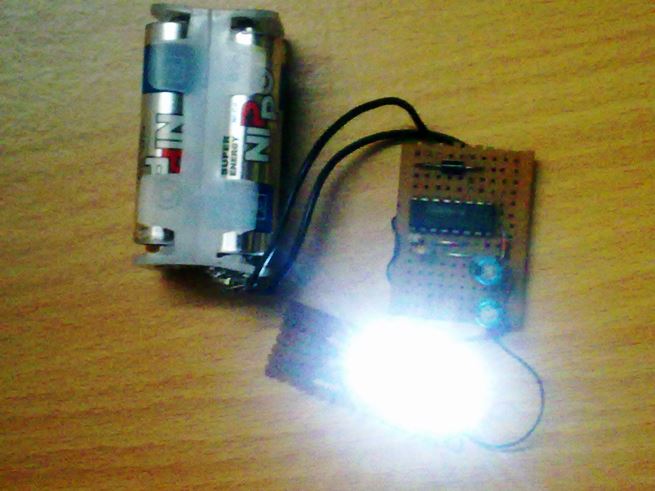
Illuminating 6 LEDs from a 3V Source
You may find it impossible illuminating 3 white LEDs fully, at 6 volts/20 mA without incorporating complex inductor assemblies.
Such a LED torch can be truly handy as the light output produced from it is reasonably high with battery lasting almost forever.
Moreover nothing could be as satisfying as building this beautiful circuit right in your home. We know that, LEDs in series always provide better results.
Simply because, just by increasing the required voltage appropriately, we are able to drive the whole series using the same amount of current as required for a single LED.
For example, if we consider a single white LED, it requires about 20 mA of current at 3.8 volts to illuminate brightly, so if we connect 3 such LEDs in parallel, would mean a current consumption of 60 mA – that’s huge, and would discharge a small battery pretty fast, within minutes.
However, if we connect the above LEDs in series and step up the voltage to about 10 volts, it would become possible to light them up using just 20 mA of current, making the whole circuit very efficient.
Using IC4049 Circuit as an Oscillator
Using the versatile IC 4049, which contains six inverter gates or NOT gates in one package, a very simple voltage stepper can be wired.
By configuring two of its gates as an oscillator, we find that 4 of its gates can be tied up in parallel to produce the required buffering to the oscillator output and step this buffered output to drive a single series of 3 LEDs.
To add up more such series you would just require increasing the number of gates (ICs) and using them as buffers for the relevant LED series.
One oscillator will be enough and may be used commonly to drive all these added buffers and the LED series.
Let’s track down the proposed circuit’s working principle.
How it Works
In the adjoining figure (click to enlarge) we see how simply a single IC 4049 and few other passive components are used to drive three white LEDs from a 6 volt source at just 20 mA current.
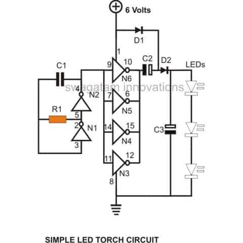
The present configuration ensures almost 100 % efficiency and thus a good battery life.
Gates N1 and N2 along with R1 and C1 are all wired up as an oscillator with a frequency determined by the values of R1 and C1.
The remaining gates N3, N4, N5 and N6 are all joined in parallel as buffers, i.e. their inputs are all linked together and connected to the frequency source from the oscillator.
Their outputs are also made into a single common outlet and terminated to the following voltage enhancer circuit.
The Voltage Multiplier Circuit
A standard configuration using two diodes and the same number of electrolytic capacitors are used to create a voltage multiplier circuit.
The above configuration will work only for alternating voltages and will double the received input.
The applied oscillating frequency from the buffers is successfully made almost twice by the above multiplier circuit.
Three high efficiency white LEDs in series are integrated at the output of the voltage multiplier circuit to complete the unit.
The LEDs receive the suitable voltage from the circuit and illuminate quite brightly.
Parts List
- R1 = 68K,C1 = 680pF,
- C2, C3 = 100 uF/ 25V,
- D1, D2 =1N4148,
- N1, N2, N3, N4 = IC 4049,
- LEDs White = 3 nos.
- GeneralPurpose PCB = As per size,
- Ni-Cd Cells = 5 nos. 1.2 volts each (rechargeable)
- Suitable Enclosure = Small plastic box to hold the circuit, batteries and the LEDs.
How to Assemble
Building the circuit of this LED torch is pretty easy, just procure all the components and solder them together with the help of the given circuit schematic.
Then it’s just a matter of connecting the battery pack to the circuit and checking its illumination.
If possible check the current consumption of the circuit using a milliammeter, should not be more than 15 to 20 mA.
Enclose the whole unit inside a suitable plastic box; make sure that the LEDs suitably protrude out of the box’s front surface.
You can use suitable reflectors to increase its light output. A fully charged battery pack should last for a very long time, almost more than five years even if used quite frequently.
PCB Layout




Questions & Answers
Just making sure:
the IC4049 has 16 pins right?
And the pin#16 and pin#13 has no connection in your circuit right?
thanks for the answer?
By the way how much is the maximum input for 7812 voltage regulator? how will I know if i used the right capacitors?
4049 has a few blank pinouts, you may refer to its datasheet.
can i use ic MN4049b
yes….
can i use ic MN4049B?
hello
can i use 4.2v laptop battery cell for it
yes you can use it.
what are the ranges of voltage (minimum to maximum) that can be used in this circuit?
with 6v supply only three LEDs and with 12V supply upto 6 LEds in series….eDs shouldbe 5mm/20mA type
you mean up to 12v battery can be used in this circuit?
will 12v last longer than 6v battery?
can I use 2.4v-4.8v nimh battery?
thamks a lot for your help sir!!!
I will always acknowledge you in my projects!!!
12V will work longer than 6V if the LEDs are connected in series.
4.8V battery will work but not 2.4V.
can i put this circuit at the output of the circuit
"Simplest Automatic Emergency Light Circuit Using IC555"?
and
can i combine the three circuits of yours? like:
"Make this 10 Step Battery Voltage Monitor Circuit"
"Simplest Automatic Emergency Light Circuit Using IC555"
"How to Build a Simple Hi Efficiency LED Torch Circuit at Home"
if I use single 1 watt led with 12v battery in this circuit what value of resistor will I use?
how many 1 watt led can I use in series using 12v battery in this circuit?
yes you can combine all these circuits together.
for 1 watt LED the above circuit won't work, and is not required.
you can simply connect the LED directly with the battery using a 20 ohm 1 watt series resistor.
you mean I cant use 1 watt led in the above circuit? why(sobbing)…
NO, you cannot use 1 watt led
is it correct that if i connect the circuit to a power source for a minute then disconnect it, the light is still glowing even there is no power source? That is what happened to my circuit! I just made it yesterday.
it's due to the stored charge inside C2, C3….
I want the details of the gates n5 & n6……………………….n I need the information of the circuit in video mode…………………pls reply fast guys I need to submit the project…………………………………………..by the way ur xplanation is exceptional
more info is given here:
https://www.homemade-circuits.com/2011/12/simple-dc-to-dc-voltage-doubler-circuit.html
I need the project report of this experiment……………….plsss mail it to mbpoint3@gmail.com or else mail me what are the important points needed to be covered in the project report………………………..
why did we use ic4049 in this circuit as well as the diodes……how would we justify it…..
it has been explained in the article.
I want to add a on off switch to it so were I fix it
in series with battery positive
Sir if I want to use 8mm 0.50 watt straw hat white leds this led will be suitable for this circuit
No, this is a low current design, it won't handle 1/2 watt LeDs
Then which type of 5mm led will be better for it……….. Flat head type, round led type, or straw hat type
any type that's rated to work at 20mA current
Hi
I am Neeraj
Is this circuit applicable for 6v 4.5ah battery
Hi
I am Neeraj
Is this circuit applicable for 6v 4.5ah battery
and I have 3 led of 3v 300ma. can I connect these led's using this circuit
to get more back up from the battery
Hi Neeraj, the above circuit is rated for 20mA only, you can use the following circuit instead:
https://www.homemade-circuits.com/2012/09/led-emergency-light-circuit-using-boost.html
make sure the coil has no more than 20 turns and use a 6 ohms 2 watt resistor in series with the LED string
How modify 3.7v mobile battery used what types led used this mobile battery please tell me sir
you can try the second circuit from this article:
https://www.homemade-circuits.com/2013/04/1-watt-led-emergency-lamp-circuit-using.html
tell me what's your exact requirement
I want 3.7v battery used power saver high effective lights circuit
power saver or power bank?
Iwant power saver led light circuit diagram used 3.7v battery
provide more details regarding LEDs, voltage etc.
Which types led used long battery Backup please tell me sir
depends on how much illumination you require,
low illumination more back-up, high illumination low back-up
What is illumination please tell me sir
it's the the level of brightness
Hello sir ..i want to put ldr to cntrol the led..where shoulf i put it…tq
hello yusinizam, connect pin4 with the pin9 junction through a 10k resistor, and then connect the LDR across positive and pin9 rail
Thank sir…
Hi Swagatham, thanks for this great idea.
The CD4049UB and CD4050B devices are inverting and
non-inverting hex buffers, respectively.
I have one CD4050B, can I use this ic instead of 4049, after some modification in the circuit….if yes how…..?
Hi Anil,
you can probably try the following with your IC.
remove the gate N3 and place it between pin4 of N2 and C1 top end…this should allow the circuit to function in the same way as with 4049 IC
….and you might also need to put another gate in series with N1…so you can remove another gate N4 from the buffer stage and connect it in series with pin3 of N1
the only draw back is we can't go below 5v..for it's the supply required by the IC4049 :(…is that right?