A simple LED torch circuit that would light up 3 white LEDs from a 6 volt supply and would make your battery last forever is described here.
A useful voltage doubler circuit is incorporated here to make a highly efficient circuit using just a handful of components.
Introduction
Learn more how to build it. White LEDs are quite renowned for producing dazzling lights at very low currents.
But, if they are not configured cleverly can in fact be pretty poor in the above respect. Learn the simple trick to optimize and make a highly efficient LED torch at home.
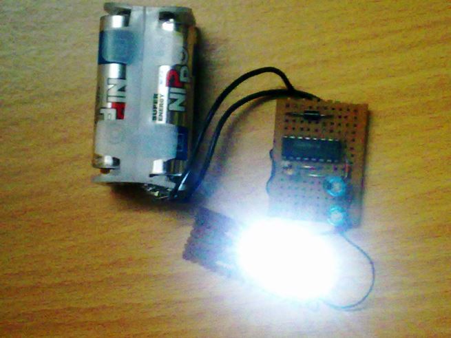
Illuminating 6 LEDs from a 3V Source
You may find it impossible illuminating 3 white LEDs fully, at 6 volts/20 mA without incorporating complex inductor assemblies.
Such a LED torch can be truly handy as the light output produced from it is reasonably high with battery lasting almost forever.
Moreover nothing could be as satisfying as building this beautiful circuit right in your home. We know that, LEDs in series always provide better results.
Simply because, just by increasing the required voltage appropriately, we are able to drive the whole series using the same amount of current as required for a single LED.
For example, if we consider a single white LED, it requires about 20 mA of current at 3.8 volts to illuminate brightly, so if we connect 3 such LEDs in parallel, would mean a current consumption of 60 mA – that’s huge, and would discharge a small battery pretty fast, within minutes.
However, if we connect the above LEDs in series and step up the voltage to about 10 volts, it would become possible to light them up using just 20 mA of current, making the whole circuit very efficient.
Using IC4049 Circuit as an Oscillator
Using the versatile IC 4049, which contains six inverter gates or NOT gates in one package, a very simple voltage stepper can be wired.
By configuring two of its gates as an oscillator, we find that 4 of its gates can be tied up in parallel to produce the required buffering to the oscillator output and step this buffered output to drive a single series of 3 LEDs.
To add up more such series you would just require increasing the number of gates (ICs) and using them as buffers for the relevant LED series.
One oscillator will be enough and may be used commonly to drive all these added buffers and the LED series.
Let’s track down the proposed circuit’s working principle.
How it Works
In the adjoining figure (click to enlarge) we see how simply a single IC 4049 and few other passive components are used to drive three white LEDs from a 6 volt source at just 20 mA current.
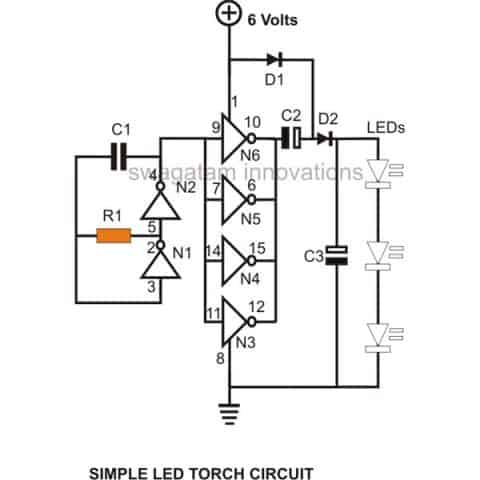
The present configuration ensures almost 100 % efficiency and thus a good battery life.
Gates N1 and N2 along with R1 and C1 are all wired up as an oscillator with a frequency determined by the values of R1 and C1.
The remaining gates N3, N4, N5 and N6 are all joined in parallel as buffers, i.e. their inputs are all linked together and connected to the frequency source from the oscillator.
Their outputs are also made into a single common outlet and terminated to the following voltage enhancer circuit.
The Voltage Multiplier Circuit
A standard configuration using two diodes and the same number of electrolytic capacitors are used to create a voltage multiplier circuit.
The above configuration will work only for alternating voltages and will double the received input.
The applied oscillating frequency from the buffers is successfully made almost twice by the above multiplier circuit.
Three high efficiency white LEDs in series are integrated at the output of the voltage multiplier circuit to complete the unit.
The LEDs receive the suitable voltage from the circuit and illuminate quite brightly.
Parts List
- R1 = 68K,C1 = 680pF,
- C2, C3 = 100 uF/ 25V,
- D1, D2 =1N4148,
- N1, N2, N3, N4 = IC 4049,
- LEDs White = 3 nos.
- GeneralPurpose PCB = As per size,
- Ni-Cd Cells = 5 nos. 1.2 volts each (rechargeable)
- Suitable Enclosure = Small plastic box to hold the circuit, batteries and the LEDs.
How to Assemble
Building the circuit of this LED torch is pretty easy, just procure all the components and solder them together with the help of the given circuit schematic.
Then it’s just a matter of connecting the battery pack to the circuit and checking its illumination.
If possible check the current consumption of the circuit using a milliammeter, should not be more than 15 to 20 mA.
Enclose the whole unit inside a suitable plastic box; make sure that the LEDs suitably protrude out of the box’s front surface.
You can use suitable reflectors to increase its light output. A fully charged battery pack should last for a very long time, almost more than five years even if used quite frequently.
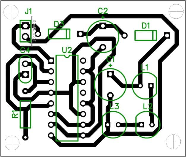
PCB Layout



Questions & Answers
One clarification. Normal rechargeable cells itself will last 4- 5 years. Then what is the advantage of using this circuit. Also whether each LED consumes 80 mW (12V / 3 led x 20 mW/ LED). Kindly correct me if i am wrong.
You can illuminate 3 or 4 LEDs in series economically using a 6V source, that’s the only advantage.
Does it imply that longevity of rechargeable cells is not connected with this circuit
The battery will have a longer life, since excess current cannot be drawn from the battery in this circuit.
Hi.
I’m going to give this circuit a run as I’m making some DIY lanterns for friends.
My issue is that i’m not sure if 3 LEDS are going to be bright enough. I was considering putting a second ‘leg” of 3 LEDs in parallel with the first string. I know doing this I should put an individual resistor on each parallel branch instead of just one leading into the LED part of the circuit. But looking at your circuit you a voltage balancing resistor doesn’t seem to be leading into the LED path. SO the question is how would adding a second branch of 3 LEDs in parallel change the circuit.
Hi,
Actually the above circuit does not make sense, because we can simply connect the LEDs in parallel directly with the battery with individual series resistors. So Please remove the circuit and just connect the LEDs in parallel directly with the battery, with each LED having its own calculated series resistor. I had designed this circuit 10 years ago and perhaps I failed to understand this basic point then…
Well it does make sense in that LEDs in parallel burn themselves out much easier and tend to cascade fail when they do as the multiple paths can create voltage/current differentials based on badly binned and dissimilar forward voltage-d LEDs and if you get one (even of the same color/batch) that is draws less voltage it’s going to hog enough current that it might cook itself and then each one down the line likely would as well without individual series resistors on each branch. Now having a resistor in series with each parallel LED (or LED grouping) would likely limit this or prevent it entirely but its more parts and just feels less elegant.
Series is a safe way to go if you can provide enough voltage.
My electrical engineering is 3 years of college about 25 years ago so it’s all pretty murky at this point and I tend to really double check things and in truth I don’t understand/recall the properties of most individual specialized items anymore… certainly not off the top of my head.
That all said my question is this. lets just look at this as a voltage boosting circuit. Does any part of it act as a voltage sink (which is what the in series resistor to an LED should/would do) to limit/take up the rest of the available voltage above what the LEDs forward voltage (~9.6 if the LEDs in your schematic above if they are white/blue) is in your series connection of them (and also limit milliamps to say 20)
Or
Is the full doubled voltage without any current limiting going through the branch of the circuit with the LEDs as things are shown. In which case I can “black box” the voltage booster away from whatever LED branches I want to run and figure out their series resistor based on whatever they are just knowing that at the beginning of that part of the circuit i’ve got 12 volts to account for.
In part I ask because i already picked up the components to tinker with this circuit and so I might as well play around with it… and also because I am trying to relearn and understand a few things and even if it turns out that I don’t need a voltage doubler (for the LED setup i’m trying to put together) I still want to understand whats going on up there… and I might end up using it for something else.
Sorry, your assumption regarding LEDs doesn’t seem to be correct. Whether it is series or parallel both can be absolutely safe for LEDs, as long as the current is limited and distributed correctly. However the efficiency of the configuration can be optimized depending on the available supply voltage, for example we have 5V then adding parallel LEDs with separate resistors will be more appropriate, on the contrary suppose if we have 12 V as the source then a series connection will work better.
Now coming back to the above circuit, since you are interested to connect more branches in it, you can do it by adding separate resistors on each branch or string. The circuit originally does not include any current control mechanism in it, therefore you will have to add those series resistors separately with each of the strings to make the illumination uniform…however the circuit would be able to support current to a given nominal level beyond that the voltage may begin dropping drastically.
A much better alternative could be studied in the following article:
https://www.homemade-circuits.com/1-watt-led-driver-using-joule-thief/
Thanks. Will go take a look.
Hi sir I cannot see the circuit diagram in this page can u pls send me the pic of circuit diagram , and also circuit for 3 v , 1 watt led touch which will run on 4 volt 1.5 ah battery which run for 10 hours
Hi sir Same circuit can u alter for 4 v 1.5 v battery , or any other circuit which run the led for whole night in my farm to make frightening wild animals ,
Ok sir but how do I do that
Hi Sidhesh, your battery is 1.5 ah, due to possible inefficiencies we can assume it as a 1 ah battery, now if you multiply 4 x 1 gives 4 watt hour, that means for a 1 watt LED the back up cannot go beyond 4 hours, no matter what circuit you try?
if you connect a series resistor with the 1 watt LED such that its current consumption is reduced to 150mA then probably it may run for 10 hours.
How to reduce to 150 ma
add a 5 ohm, 1 watt resistor in series with your LED
Thanks sir it’s visible now ,
Even less led also do
Hi Sidhesh, I have corrected the issue please check it now,
a 1 watt LED will not run for 10 hours from a 4V/1.5 AH battery, it may run for a maximum of 5 hours
Sir can I use 4 volt 500 milliamps battery for this circuit if not possible means kindly design me a led torch light circuit using the above mentioned battery. Thanks in advance.
You will have to solve the above mentioned formula for getting the right value….if it's as per the above formula then it should be correct
Sir can I use 20E 1/4 watts resistors
Ranganathan, 4V will produce 8V at the output which won't be sufficient for illuminating 3 LEDs, therefore cannot be used here.
Actually a circuit is not required at all, you can simply connect your LEDs in parallel with your 4V battery terminals….but make sure each of the LEDs has a resistor having a value, which can be calculated with the following formula
4 – 3.3 / LED current
the circuit is wudwerful. how can the battery be recharged?
thanks….through an external source
i want to make a head torch for…..outdoor treeking… so is it possible…..with this circuit
yes it is possible!
sir can i connect 3x AAA batteries.. means 4.2 volt….
Kuntal, yes you can use 3 AAA cells in series with the above circuit….the back time will depend on the battery charge level and overall condition, I cannot say it specifically.
alternatively you can try this software:
https://www.homemade-circuits.com/p/battery-calculator.html
sir, can i connect 3x AAA batteries..means 4.5 volt……then pls say the time of lightning is so longer.. or shorter because …. i want to build it for my outdoor camping……
What's the Formula for the Frequency? tnx
Not sure about the formula, could be as given in the following article:
https://en.wikipedia.org/wiki/RC_time_constant
the only draw back is we can't go below 5v..for it's the supply required by the IC4049 :(…is that right?
4049 can work from 3V to 15V, it's the 74XX version which has this limitation
ohh!!. so it means I can use 2 x 1.5v battery cell??? 😀 🙂 ^_^
it should be slightly over 3V, lower than 3V can cause malfunctioning
Hi Swagatham, thanks for this great idea.
The CD4049UB and CD4050B devices are inverting and
non-inverting hex buffers, respectively.
I have one CD4050B, can I use this ic instead of 4049, after some modification in the circuit….if yes how…..?
Hi Anil,
you can probably try the following with your IC.
remove the gate N3 and place it between pin4 of N2 and C1 top end…this should allow the circuit to function in the same way as with 4049 IC
….and you might also need to put another gate in series with N1…so you can remove another gate N4 from the buffer stage and connect it in series with pin3 of N1
Thank sir…
Hello sir ..i want to put ldr to cntrol the led..where shoulf i put it…tq
hello yusinizam, connect pin4 with the pin9 junction through a 10k resistor, and then connect the LDR across positive and pin9 rail
What is illumination please tell me sir
it's the the level of brightness
Which types led used long battery Backup please tell me sir
depends on how much illumination you require,
low illumination more back-up, high illumination low back-up
Iwant power saver led light circuit diagram used 3.7v battery
provide more details regarding LEDs, voltage etc.
I want 3.7v battery used power saver high effective lights circuit
power saver or power bank?