• Skip to main content
  • Skip to primary sidebar

Homemade Circuit Projects

Need circuit help? Post them in the comments! I've answered over 50,000!

Blog | Categories | About | Hire Me | Contact | Calculators-online
You are here: Home / Datasheets and Components / High Voltage Transistor MJE13005 – Datasheet, Application Notes

High Voltage Transistor MJE13005 – Datasheet, Application Notes

Last Updated on June 30, 2026 by Swagatam 16 Comments

The article relates us with the important features and specifications of MJE13005 device, which is a high voltage, high speed transistor, applicable for many different electronic circuit designs.
Let's try to understand the pin outs and technical specs of the device:

Table of Contents
  • Pinout Diagram
  • Main Features
    • Main Application Areas
    • Maximum Tolerable Ratings
    • Technical Specifications
    • Sources

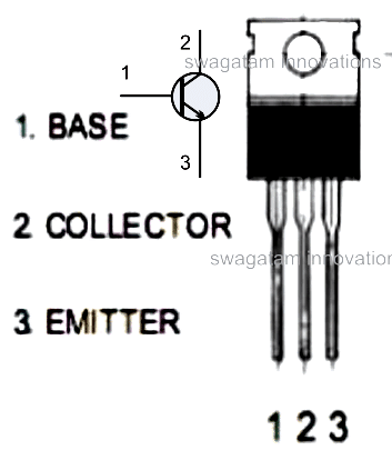
Pinout Diagram

Main Features

  • Package - TO-220AB (typically recommended)
  • Type - NPN Silicon
  • Power Handling Capaciy - 75 Watts,
  • Maximum Current Handling Capacity - 4 Amps
  • Maximum Voltage Handling Capacity - Not less than 400V

Main Application Areas

High voltage circuits, switch mode power supplies, motor control, switching regulators, inverters, solenoid drivers.

Maximum Tolerable Ratings

  • Maximum sustainable collector to emitter voltage = 400V DC (700V DC pulsed)
  • Maximum tolerable emitter to base voltage = 9V DC
  • Maximum sustainable collector to emitter current = 4 amps (8 amps pulsed)
  • Maximum continuous base current = 2 amps (4 amps pulsed)

Technical Specifications

  • Base emitter saturation voltage = typically 1.2V
  • DC current gain (hFE) = typically around 20 to 60
  • Application Circuits

A couple of application circuits using the MJE13005 have been discussed in the following articles:

Simple SMPS Circuit

Simple Transformerless Power Supply

Sources

  • onsemi.com

You'll also like:

  • zener 2Transistor Zener Diode Circuit for Handling High Current Stabilization
  • smallsignalmosfetpinoutLow Power MOSFET 200mA, 60 Volts Datasheet
  • IC 4013 Datasheet, Pinout Details
  • IC 4043 dtasheet pinoutUnderstanding IC 4043B, IC 4044B CMOS Quad 3-State R/S Latch – Working and Pinouts

Filed Under: Datasheets and Components Tagged With: Application, Datasheet, High, MJE13005, Transistor, Voltage

About Swagatam

I am an electronics engineer and doing practical hands-on work from more than 15 years now. Building real circuits, testing them and also making PCB layouts by myself. I really love doing all these things like inventing something new, designing electronics and also helping other people like hobby guys who want to make their own cool circuits at home.

And that is the main reason why I started this website homemade-circuits.com, to share different types of circuit ideas..

If you are having any kind of doubt or question related to circuits then just write down your question in the comment box below, I am like always checking, so I guarantee I will reply you for sure!


Previous Post: « Transformerless Power Supply Circuit using MJE13005
Next Post: How to Connect a Relay through an Opto-Coupler »

Reader Interactions

Questions & Answers

Total Posts: 16
Newest Oldest
satheesh k Nalluswamy
February 8, 2016 • 10 years ago #38534

Sir,
Good day to you
Can I use this BT136-600D instead of (MJE13005 , TO-220AB )

Reply
SwagatamAdmin
February 9, 2016 • 10 years ago #38560

satheesh, BT136 is a triac, whereas MJE13005 is a BJT, both cannot be interchnaged

Reply
satheesh k Nalluswamy
February 9, 2016 • 10 years ago #38571

Sir,
Good morning thanks for your quick reply
Sorry sir seller told me this. So I asked you to confirm .BJT have any other equivalent number?

Reply
SwagatamAdmin
February 9, 2016 • 10 years ago #38574

satheesh, both the devices are rated to work at high voltages, but BT136 is specified to work with AC while MJE with DC…so are entirely different in that respect.

Reply
Chandrachur Maitra
April 3, 2017 • 9 years ago #49541

Dear sir, can I made an 100-120watts inverter using MJE13005?

Reply
SwagatamAdmin
April 4, 2017 • 9 years ago #49564

Chandrachur, yes that may be possible if the input is 310V DC

Reply
raja rajai
June 28, 2017 • 9 years ago #51398

Dir sir,can I made an 1000 watts inverter using MJE13005??

Reply
SwagatamAdmin
June 28, 2017 • 9 years ago #51420

you can may be, if the DC input is at 330V

Reply
Loki
November 25, 2017 • 9 years ago #56103

Sir can i use 13005 transistor to design 12v dc to 220v ac Inverter
And can i use 13005 to build induction heater

Reply
SwagatamAdmin
November 25, 2017 • 9 years ago #56106

Loki, MJE13005 is suitable for high voltage applications, not for 12V or 24V applications, so no you cannot use it for inverter or induction circuits.

Reply
Loki
November 26, 2017 • 9 years ago #56108

Sir is ampere is the problem here
If yes can i use many transistor (13005) in parallel to increase it

Reply
SwagatamAdmin
November 26, 2017 • 9 years ago #56109

you can put them in parallel but use a common heatsink for all of them which are in parallel.

https://www.homemade-circuits.com/transistor-facts/

Reply
Loki
November 26, 2017 • 9 years ago #56111

I connected 12 13005 in parallel so total ampere of 12*4=48
But still it get heated up when i conected it to my Inverter. The original transistor of my inverter is irfz44(mosfet) which is not available in my area where as 13005 is available at really cheap

Reply
SwagatamAdmin
November 26, 2017 • 9 years ago #56112

you will have to use a very large heatsink, and single heatsink for the all the BJTs on each channel…two separate heatsinks for the two channels.
If it is cheap then it could duplicate one.

You should try other recommended ones like 2N3055, TIP35 etc.

Reply
Robert Tyabji
September 10, 2022 • 4 years ago #133089

Hi Swagatam,
The dual-UV tubes from my fish pond have stopped working. I checked the two filaments (about 9 ohms each) and found them to be good. I extracted the dual tubes from their glass casing and removed the driver board, which contains dual full-wave rectifiers, two 13005 transistors and associated components, including what looks like a small transformer or choke on the output side. I powered the board up (220VAC) and found that one of the outputs measures 12VDC but the other has zero out. I tried connecting the working output to one of the tubes but it doesn’t light.
I was hoping you could give me some guidance as to how these UV tubes work, working voltage, etc?
Very grateful for any advice/guidance you can offer.
Thanks in advance

Reply
SwagatamAdmin
September 10, 2022 • 4 years ago #133090

Hi Robert,
As far as I know, UV lamps require high frequency, high voltage of over 200 V to light up. The transformer consists of a low voltage winding to provide the discharge current supply across the tube and a 240V winding to generate a initial static voltage for starting the tube conduction.
If your transformer is not producing the high voltage then the circuit could be malfunctioning probably due to a blown transistor. The fault can be confirmed by practically checking the circuit.

Reply

Need Help? Please Leave a Comment! We value your input—Kindly keep it relevant to the above topic! Cancel reply

Your email address will not be published. Required fields are marked *

Primary Sidebar


Categories

  • Arduino Projects (95)
  • Audio and Amplifier Projects (134)
  • Automation Projects (18)
  • Automobile Electronics (103)
  • Battery Charger Circuits (89)
  • Datasheets and Components (109)
  • Electronics Theory (150)
  • Energy from Magnets and Earth (40)
  • Games and Sports Projects (11)
  • Grid and 3-Phase (20)
  • Health related Projects (27)
  • Home Electrical Circuits (13)
  • Indicator Circuits (16)
  • Inverter Circuits (100)
  • Lamps and Lights (163)
  • Meters and Testers (72)
  • Mini Projects (28)
  • Motor Controller (68)
  • Oscillator Circuits (30)
  • Pets and Pests (15)
  • Power Supply Circuits (91)
  • Remote Control Circuits (50)
  • Security and Alarm (65)
  • Sensors and Detectors (107)
  • SMPS and Converters (46)
  • Solar Controller Circuits (62)
  • Temperature Controllers (44)
  • Timer and Delay Relay (50)
  • Voltage Control and Protection (44)
  • Water Controller (37)
  • Wireless Circuits (31)


Circuit Simulator

circuit simulator image


Subscribe to get New Circuits in your Email


Other Links

  • Privacy Policy
  • Cookie Policy
  • Disclaimer
  • Copyright
  • Videos
  • Sitemap

People also Search

555 Circuits | 741 Circuits | LM324 Circuits | LM338 Circuits | 4017 Circuits | Ultrasonic Projects | SMPS Projects | Christmas Projects | MOSFETs | Radio Circuits | Laser Circuits | PIR Projects |


Recent Comments

  • Swagatam on 2 Cool 50 Watt Inverter Circuits for Students and Hobbyists
  • way on 2 Cool 50 Watt Inverter Circuits for Students and Hobbyists
  • Swagatam on 2 Cool 50 Watt Inverter Circuits for Students and Hobbyists
  • Swagatam on The Perfect FM Radio Circuit using TDA7000 IC
  • Swagatam on 9 Simple Sine Wave Generator Circuits Explored

Social Profiles

  • Twitter
  • YouTube
  • Instagram
  • Pinterest
  • My Facebook-Page
  • Stack Exchange
  • Linkedin

© 2026 · Swagatam Innovations