• Skip to main content
  • Skip to primary sidebar

Homemade Circuit Projects

Need circuit help? Post them in the comments! I've answered over 50,000!

Blog | Categories | About | Hire Me | Contact | Calculators-online
You are here: Home / Grid and 3-Phase / Emergency Generator Circuit Power Distribution

Emergency Generator Circuit Power Distribution

Last Updated on May 21, 2026 by Swagatam 1 Comment

In this post I have explained a twin generator network system to be used for two separate houses during power failure and through automatic changeover.The idea was suggested by Mr. Ahmad.

Table of Contents
  • The Circuit Idea and Objective
    • A Strange Looking Design
    • The Current Limiting Circuit

The Circuit Idea and Objective

Thank you for posting the new and useful circuits. I am one of interesting in your website. This work is great done and a good information with best details explanations. In either for hobbyists and professionals.

I have an idea about the Circuit breaker with different options circuit. In short words, This circuit will do the following things:

It has two different mains inputs : the both for up to 220 volt with one is 3.A Max. The second is 8.A Max. 2.

It has two different mains outputs: the both with same input with limited current to Max is 1.A drain in the outputs.

It should be exchange the energy from A Input to B output or from B input to A output . If suppose that :

A has power main with same time B has an absent or failure of power Then - A gives B the electrify with Limited current to 1 ampere max. B has power main with same time A has an absent or failure of power.

Then - B gives A the electrify with Limited current to 1 ampere max.If A or B the current max over to 1 ampere in the drain - the Circuit should break then after while back the electrify again as the rules when A or B has an absent or failure of power.

Now, If both A and B input have electricity then the circuit should give nothing in outputs.

According to the rules I made the part of it using ic 4077, which is gate of XNOR and as my background is Computer Science.

I know the gates so I studied b before on it, However, I am interesting of making this circuits. My knowledge of electronic is small but I made some working circuits. I know the components well.

So, here the circuit that I created it through through the Circuit Wizard. and it working well as it only:

A has power mains with same time B has an absent or failure of power Then - A gives B the electricity.

B has power mains with same time A has an absent or failure of power Then - B gives A the electricity. If both A and B input have electricity then the circuit should give nothing in outputs.

So, It needs additional things like control of currents to Limited 1 ampere as always as possible. also it needs to time delay to back turn on the electricity to an absent or failure of power on points of A or B. the delay could be to up to 1 minute.

Finally,I need some information about how to make it on oversee so could you help me please ? I attached the image of circuit within this email.
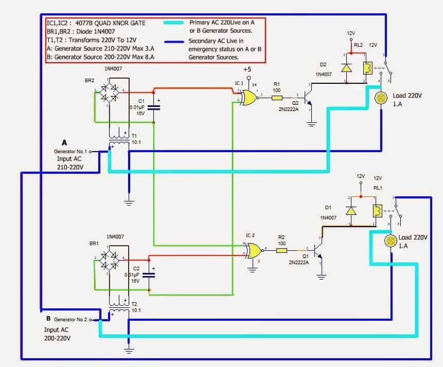
Emergency Generator Circuit Power Distribution

In fact this circuit has particular method so it will work as an emergency mains line-status for example of two houses with two own generators. Whenever either houses have electricity the other house will feed with this too with limited current and limited option.

So, If House No. 1 has a Generator powering by 8A max ... ->

Then B is house No.2 can take some little current of electricity. That's only if House No.2 has stopped it own generator for take a rest of time after while of working.

If again, House No.2 has Generator powering by 3A max ...-> Then House No.1 can take some little of current of electricity.

That's only If House No.1 has stopped it own generator for a take rest of time after while of working.

In main while, If House No1. gives House No.2 or vice versa .. it should taken amperage of 1.A as max as possible also in case of overcome then this circuit will take a brake and it back after 1 minute or less.

That's enough for emergency lines with no any affect of origin house's current.

Plus, those Generator may working synchronization but not always. So, When both working there no need to House No.1 gives House No.2 or vice versa in case both their own generating power working on.

So, in this case it needs to give nothing in the output due fear of short of hazard of two AC mains met.

In addition, this circuit may use it in other various applications, if it haven full control to brake of any met on tow AC mains in same time. or other thing like an inverter to join it directly with mains with free errors or risk on both house's mains and inverter.

This is maybe work so I just now have an idea and I will try to do that if you help me. I can provide more information if necessary.

Thank you again and I wish you a great time of day!

I attached circuit diagram for more details.

Best wishes,

Ahmed

A Strange Looking Design

1) The circuit looks incorrect in many ways

2) The emitter of the transistors are connected with the mains line and not the bridge negative.

3) The gate inputs are cross linked so if one of the generators does not have power then the relevant gate will have no defined signal to detect and might hang in an undefined zone.

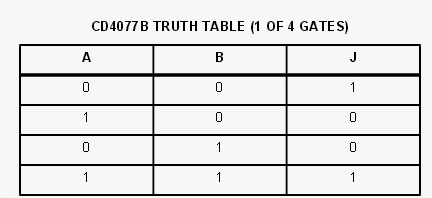
The IC 4077 has the following truth table, so relating this to the above circuit looks confusing:
To me the circuit looks dangerous.

The Current Limiting Circuit

As requested in the above discussion, the current limit across the two generator outputs can be controlled by adding a small circuit stage as given in the following diagram:
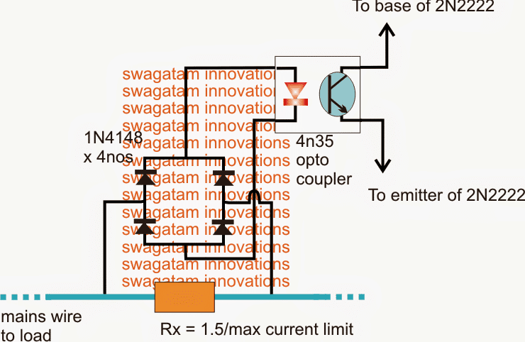
current sensing optocoupler circuit

The time delay feature can also be implemented easily by introducing the unused gates from the IC 4077, however unless the point no 3) is corrected or addressed, it won't be a good to assign it in the circuit.

You'll also like:

  • 50V BLDC motor controller using L6235 IC module50V 3-Phase BLDC Motor Driver
  • pwmvoltageregulatorHow to Make a 3 Phase VFD Circuit
  • simplesinglephasingpreventercircuitSingle Phase Preventor Circuit
  • 3 Phase Brushless (BLDC) Motor Driver Circuit

Filed Under: Grid and 3-Phase Tagged With: Distribution, Emergency, Generator, Power

About Swagatam

I am an electronics engineer and doing practical hands-on work from more than 15 years now. Building real circuits, testing them and also making PCB layouts by myself. I really love doing all these things like inventing something new, designing electronics and also helping other people like hobby guys who want to make their own cool circuits at home.

And that is the main reason why I started this website homemade-circuits.com, to share different types of circuit ideas..

If you are having any kind of doubt or question related to circuits then just write down your question in the comment box below, I am like always checking, so I guarantee I will reply you for sure!

Previous Post: « Simple Scrolling RGB LED Circuit
Next Post: Make this Geyser Water Heater Timer Circuit with Automatic Switch OFF »

Reader Interactions

Questions & Answers

Total Posts: 1
Newest Oldest
SwagatamAdmin
July 14, 2016 • 10 years ago #42620

Dear Ahmad, I checked your diagram but could not correctly understand the configuration, the relay connection and the current limiting connection with the IC 555 appears to be incorrect.

Reply

Need Help? Please Leave a Comment! We value your input—Kindly keep it relevant to the above topic! Cancel reply

Your email address will not be published. Required fields are marked *

Primary Sidebar

My YouTube Channel

Circuit Simulator: Draw and Simulate Schematics

circuit simulator image

Categories

  • Arduino Projects (95)
  • Audio and Amplifier Projects (134)
  • Automation Projects (18)
  • Automobile Electronics (104)
  • Battery Charger Circuits (90)
  • Datasheets and Components (109)
  • Electronics Theory (151)
  • Energy from Magnets and Earth (43)
  • Games and Sports Projects (11)
  • Grid and 3-Phase (20)
  • Health related Projects (27)
  • Home Electrical Circuits (13)
  • Indicator Circuits (16)
  • Inverter Circuits (98)
  • Lamps and Lights (161)
  • Meters and Testers (72)
  • Mini Projects (28)
  • Motor Controller (68)
  • Oscillator Circuits (30)
  • Pets and Pests (15)
  • Power Supply Circuits (91)
  • Remote Control Circuits (50)
  • Security and Alarm (65)
  • Sensors and Detectors (107)
  • SMPS and Converters (46)
  • Solar Controller Circuits (62)
  • Temperature Controllers (44)
  • Timer and Delay Relay (51)
  • Voltage Control and Protection (44)
  • Water Controller (37)
  • Wireless Circuits (31)

Subscribe to get New Circuits in your Email

Other Links

  • Privacy Policy
  • Cookie Policy
  • Disclaimer
  • Copyright
  • Videos
  • Sitemap

People also Search

555 Circuits | 741 Circuits | LM324 Circuits | LM338 Circuits | 4017 Circuits | Ultrasonic Projects | SMPS Projects | Christmas Projects | MOSFETs | Radio Circuits | Laser Circuits | PIR Projects |

Recent Comments

  • Martins Vita on Understanding IC 4043B, IC 4044B CMOS Quad 3-State R/S Latch – Working and Pinouts
  • Swagatam on Inverter Circuit with Feedback Control
  • Jerry Adeosun on Inverter Circuit with Feedback Control
  • Swagatam on Adjustable Voltage Regulator Circuit using LM324 IC with Over Current Protection
  • David on Adjustable Voltage Regulator Circuit using LM324 IC with Over Current Protection

Social Profiles

  • Twitter
  • YouTube
  • Instagram
  • Pinterest
  • My Facebook-Page
  • Stack Exchange
  • Linkedin

Calculators

  • ZVS Induction Heater + Tank Calculator Tool
  • Zener Diode Calculator
  • Wire Current and Thickness Calculator (Ampacity Calculator)
  • Voltage Divider Calculator
  • Transistor Base Resistor Calculator
  • Transistor Astable Multivibrator Calculator
  • TL431 Calculator
  • Solar Panel, Inverter, Battery Calculator
  • Ferrite Core Air Gap Calculator Tool
  • Parallel MOSFET Calculator Tool: How to Connect MOSFETs in Parallel Safely
  • LC Resonance Calculator for EV Battery Charger Circuits
  • LED String Series Resistor Calculator
  • PFC (Power Factor Correction) Calculator Tool: 3kW
  • Passive Power Factor Correction (PFC) Calculator
  • LM567 IC Calculator Tool
  • SMPS Flyback Boost Converter Calculator
  • Shunt Resistor Calculator for Ammeters
  • SCR and Triac Gate Resistor Calculator
  • Battery Back up Time Calculator
  • Boost Converter Calculator (Non-Isolated)
  • Bootstrap Capacitor Calculator
  • Buck Converter Calculator
  • Buck-Boost Converter Calculator
  • Capacitance Reactance Calculator
  • DCM Flyback Transformer & Wire Gauge Wire Size Calculator Tool
  • Filter Capacitor Calculator
  • IC 4047 Calculator (Frequency and PWM)
  • IC 4060 Calculator
  • IC 555 Astable Calculator
  • IC 555 Monostable Calculator
  • IC SG3525, SG3524 Calculator
  • Inductance Calculator
  • Induction Heater Inductor and Resonant Frequency Calculator
  • Induction Heater Work Coil Calculator
  • Inverter LC Filter Calculator
  • LC Resonance Calculator
  • LED Current Calculator
  • LM317, LM338, LM396 Calculator
  • NAND/NOT Gate RC Values Calculator
  • NOT, NAND Gate Frequency Calculator
  • Notch Filter Calculator Tool
  • Ohm’s Law Calculator
  • Phase Angle Phase Shift Calculator
  • Power Factor (PF) Calculator
  • RC Filter Calculator
  • Reactance Calculator
  • Sine Table Calculator for SPWM Arduino Code
  • Small Signal Transistor(BJT) and Diode Quick Datasheet
  • SMPS Calculator for Toroidal Ferrite Transformers
  • SMPS Flyback Transformer Calculator – Design by Target Duty Cycle
  • TL431 Calculator
  • Op-Amp Hysteresis Resistor Calculator

© 2026 · Swagatam Innovations