A simple RGB (Red, Green, Blue) moving or scrolling LED display can be made using a few 4017 ICs. I have explained the procedure in detail.

Understanding RGB LED
RGB LEDs have become quite popular these days due to its three-in-one color feature, and because these can be driven independently using three distinct supply sources.
I have already discussed one interesting RGB color mixer circuit, which can be used to manually set the color intensities of the LEDs for producing unique color combinations through gradual transitions.
In the proposed RGB scrolling LED circuit we incorporate the same LED for implementing the effect.
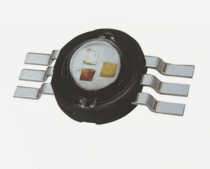
The following image shows a standard RGB LED with independent pinouts for controlling the three embedded RGB LEDs.
We'll require 24 of these LEDs for producing intended scrolling effect, once procured these may be assembled serially as shown in the following image:
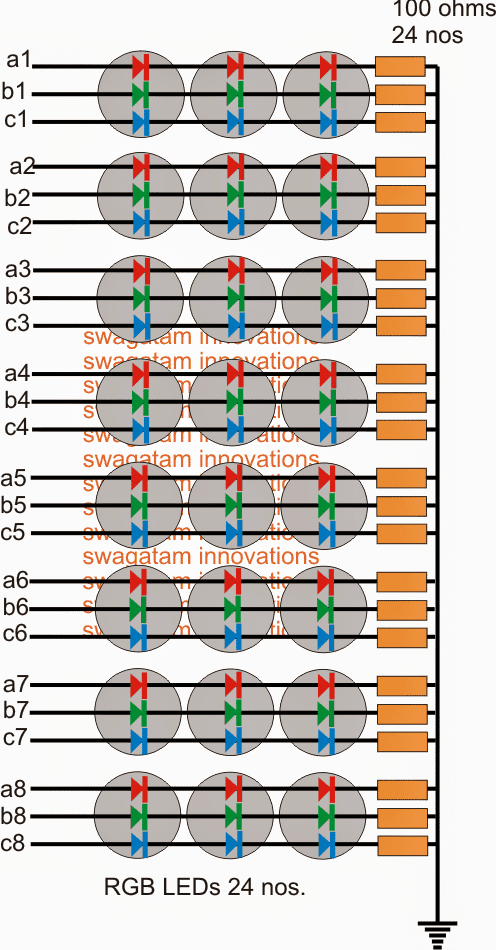
As can be seen , the cathodes are all made common and grounded via individual 100 ohm resistors (connected to the negative supply f the circuit).
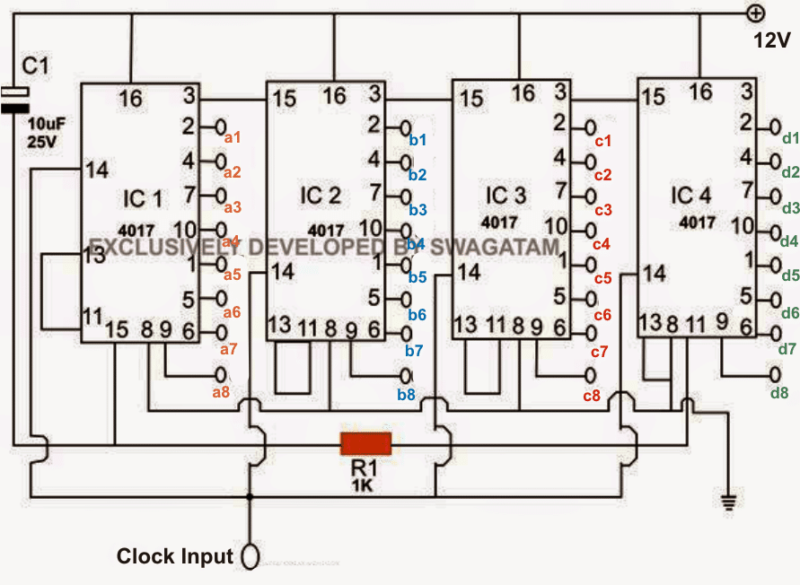
The anode ends can be seen designated with some relevant numbers which need to be appropriately connected with the respective output pinouts of the IC 4017 circuit as shown in the following figure:
How the Circuit Functions
The circuit functioning may be understood with the help of the following points:
We can see four IC 4017, 10 stage Johnson's decade counter/divider device which are cascaded in a special way such that the intended scrolling effect is achieved from the design.
Pin#14 which is the clock input of the ICs are all hooked up together and integrated with a clock source, which can be easily achieved from any standard astable circuit such as a IC 555 atable, transistor astable, a 4060 circuit or simply a NAND gate oscillator circuit.
The speed of the frequency set on the astable circuit decides the speed of the scrolling effect of the LEDs.
When power is switched ON, C1 instantly forces pin#15 of IC1 to go high momentarily. This pulls pin#3 of IC1 to a high while the remaining pinouts of IC1 are all set to zero logic.
With pin#3 of IC1 going high causes pin#15 of IC2 to also go high, which similarly puts pin#3 of IC2 at a high logic and all its other pinouts at logic zero......this in turn forces IC3 and IC4 to go through an identical set of pinout orientation .
So during power switch ON all the 4017 ICs attain the above condition and stay disabled making sure that initially all the RGB LEDs are kept switched OFF.
However the moment C1 charges fully, pin#15 of IC1 is relieved from the high created by C1, and now it's able to respond to the clocks, and in the process the high logic sequence from its pin#3 moves to the next pin#2....the first RGB string now lights up (first RED string lights up).
With pin#3 of IC1 becoming low, IC2 too now becomes enabled and quite similarly gets ready to respond to the subsequent clock at its pin#14.
Therefore the moment IC1 logic sequence shifts further from its pin2 to pin4, IC2 corresponds by pushing the pinout high from its pin#3 to pin#4....the next RGB string now lights up (green string lights up and replaces the previous red LED string, the red being moved to the next RGB string).
With the subsequent clocks at pin#14 of the ICs the same is followed by IC 3 and IC4, such that the RGB string now appears to be moving or scrolling across the given 8 subsequent LED strips.
As the sequencing proceeds across the 4 cascaded 4017 ICs, at some point of time the last logic pulse reaches pin#11 of IC4, as soon as this happens the high logic at this pin instantly "pokes" pin#15 of IC1 and forces it to reset and return to its initial position, and the cycle starts afresh....
The above RGB scrolling effect may not be too impressive, since the moving pattern would be in the manner R>G>B......, that is one color appearing behind the other.
In order to achieve a more interesting looking pattern in the manner R>R>R>R>G>G>G>G>B>B>B>B.....and so on, we need to implement the following circuit, it shows a 4 channel design, for more number of channels, you may simply go on adding the IC 4017 ICs in the identical, fashion as explained in the the following paragraphs.
RGB Moving Alphabet Display Circuit
This next circuit is designed to generate a sequencing pattern over a group of Red, Green, Blue, or RGB LEDs producing a beautiful moving or shifting transition effect from red, to green, to blue and back to red.
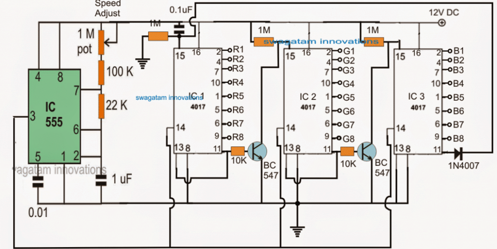
The main control circuit for the proposed RGB LED alphabet chaser circuit can be witnessed below, consisting of 3 Johnsons decade counter 4017 ICs and a clock generator IC 555.
How the RGB Effect Works
Let's first try to understand the role of this stage and how it's supposed to carry out the running RGB LED effect.
The 555 IC astable clock generator stage is included for generating the sequencing pulse for the 3 ICs, whose pin14 can be seen combined and joined with the output of the IC 555 for the required triggering.
When power is switched ON, the 0.1uF capacitor connected with pin15 of the IC1 4017 resets this IC such that the sequencing is able to begin from pin3 of this IC, that is from pin3>2>4>7>10...and so on in response to every clock pulse at its pin14.
However at the onset, when it's reset by the 0.1uF cap, except pin3 all its output pins become low including its pin11.
With pin11 at zero, the pin15 of IC2 is unable to get a ground potential and therefore it stays disabled, and the same happens with IC3 as well...so IC2 and IC 3 stay disabled for the moment, while IC1 begins sequencing.
Now as a result IC1 outputs start sequencing producing a sequencing (shifting) "high" across its output pins from pin3 towards pin11, until finally the sequence high reaches pin11.
As soon as pin11 becomes high in the order, the pin13 of IC1 also becomes high which instantly freezes IC1, and the high logic at pin11 gets locked....the IC now remains in this position unable to do anything.
However the above triggers the associated BC547, which instantly enables IC2 which now imitates IC1 and starts sequencing from its pin3 towards pin11, one by one....and quite identically as soon as the pin11 of IC2 goes high, it likewise gets locked and enables IC3 to the repeat the procedure.
IC3 also follows the footprints of the earlier ICs and as soon as the sequencing logic high reaches its pin11, the logic high is transferred to pin15 of IC1....which instantly resets IC1 restoring the system back to its original form, and IC1 yet again begins the sequencing process, and the cycle keeps repeating itself.
Circuit Diagram
We learned and understood how exactly the above RGB controller circuit is supposed to function with the stipulated sequencing procedures, now it would be interesting to see how the sequencing outputs from the above circuit may be used with a compatible driver stage for producing the scrolling or moving RGB LED over a selected set of alphabets.
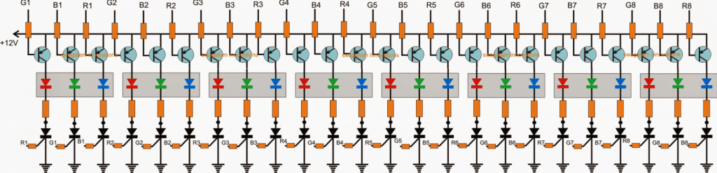
All transistors are 2N2907
All SCRs are BT169
SCR gate resistors and PNP base resistors are all 1K
LED series resistors will be as per the LED current.
The above image depicts the RGB driver stage, we can see 8 numbers of RGB LEDs utilized (in the shaded square boxes), this is because the discussed 4017 Circuit is designed to produce 8 sequential outputs and therefore the driver stage too accommodated 8 numbers of these LEDs.
To learn more about RGB LEDs you can refer to the following related posts:
RGB flasher, controller circuit
The Role of the SCRs
In the design SCRs can be seen included at the negative ends with each of the LEDs and also PNP transistors over the positive ends of the LEDs.
Basically the SCRs are positioned for latching the LED illumination while the PNP is connected exactly for the opposite that is for breaking the latch.
The sequencing or rather the typical alphabet scrolling effect is implemented by assigning the various LEDs in the following pattern:
How it Works
All the red LEDs from the RGB modules can be seen connected with the IC1 outputs, the green LEDs with the IC2 outputs and the blue LEDs with the IC3 outputs, via the corresponding SCR gates. When the SCRs are triggered the relevant LEDs become illuminated in a chasing sequence.
As explained in the earlier section, the IC1, IC2, and the IC3 are rigged in a way that the ICs respond in a cascaded fashion, wherein IC1 begins sequencing first, followed by IC2 and then IC3, the cycle then keeps repeating itself.
Therefore when IC1 begins sequencing all the red LEDs in the respective RGB modules get triggered and latched.
When IC2 is enabled with the sequencing it starts illuminating and latching the green LED in the array via the concerned SCRs, but simultaneously also breaks the RED led latch via the associated PNP transistors. The same is carried out by the IC3 outputs but this time for the green LEDs in the RGB modules,
When green LED sequencing elapses it's yet again replaced by the IC1 for processing the red LEDs, and the entire procedure starts simulating a dazzling RGB LED scrolling effect.
Scrolling Display Simulation
The above shown animated simulation provides an exact replica of the scrolling of the LEDs that may be expected from the proposed design.
The indicated running white spots on the SCR gates indicate the triggering and the execution of the latching function by the SCRs, while the PNP base white spots indicate the breaking of the relevant SCR latches.
Single LEDs are shown in the sequence, but depending on the supply voltage more numbers of series LEDs could be inserted within each of the RGB channels. For example with a 12V supply 3 LEDs may be incorporated on each of the channels, with 24V this may be increased to 6 LEDs on each of the channels.
Example Welcome Scrolling Simulation
How to configure the above effect for creating a running or moving RGB LED alphabets

The above example shows a classic RGB moving graphical alphabet simulation using the above explained circuit.
Each alphabet can be seen wired with the red, green and the blue LEDs from the 8 RGB LED modules.
The series parallel connections can be a little complex, and might require some experience and skill, the following articles can be studied for understanding the calculations involved for wiring LEDs in series and parallel:
How To Calculate and Connect LEDs in Series and Parallel
Many different innovative patterns can be designed and implemented using ones own creative imaginations and by wiring the RGB LEDs appropriately across the sequence.


Questions & Answers
This isn’t going to work for what I was planning as I was intending to use common Cath tri color LED’s so don’t bother. I need to delete my posts
This project is very interesting, but how can I use it to write multiple words not just welcome.
Pretty sure to get to that level, you are going to need the power of a processor circuit, in fact, I know that is what would be needed. Getting into computation processes for that. Way above what is generally done here. This takes a lot of memory space on the processor.
Multiple words is not possible, you can have only a 7 letter word or figure in this circuit.
in your article above the supply rail is 12 dc. Can this circuit be run at 9v dc with the led’s resister at 470 ohms and using RGB led’s instead of single led’s
Bernie, the value of the resistor you choose will simply limit the current the LED is working at up to a point, if the resistance is too much the LED will just not light to a level visable, that is unless you use too little resistance. I’m way late on this but I just now got here. Too little resistance will just cause the LED to burn out and not work at all. You need to keep the total current through the LED below around 20 milli amps or less, to around 5 milli amps. Anything above say 15 or 15 milli amps shortens the life and you won’t really notice any change in brightness. The LED has its predetermined max current tolerance @ the forward voltage it works at, each color is slightly different, and by ohms law, it’s all relevant.
The LEDs are RGB modules, so you can use them….. 9 V will also work with 470 ohm resistor
Thanks for the reply
Ok sir and thanks for all u have done……….but how can I increase the no.s of led upto 50 nos
for increasing the number of LEDs you will have to incorporate transistor driver stages across the various outputs of the 4017 ICs.
I have updated the new diagram you may check it out.
Ok but which smps can I use
for the circuit and which volt and wat will be the ampere for the circuit thanks
any 12V DC supply will do, I'll be updating the article soon with a modified design which will be exactly as per the video you had sent.
Hello sir .is this the circuit which i am requesting for pixel led …….Thank u
hello basit, yes the circuit can be modified as per the video sent by you…presently it's not exactly as you may want it.
what does NOS mean?
numbers…quantity