In this post we study a simple water heater timer controller circuit which can be used in bathrooms for automatically switching OFF a geyser or a water heater unit after a predetermined time period as preferred by the user. The idea was requested by Mr. Andreas
Technical Specifications
Many of us when we need hot water we do switch on and sometimes we forget to switch off back after hours of wasted time and most important money. So what we need here its a circuit of "one shot timer" of two preset options such half hour and one hour.
This can be achieved by means of a press switch and leds (will show when it is on) Also should be another switch acting as reset when for any reason we decide to stop this process.
Since this circuit must kept small as can be, this should be transformerless and the output to load will go thru a set of relay 10A contacts.
Many thanks,
Andreas
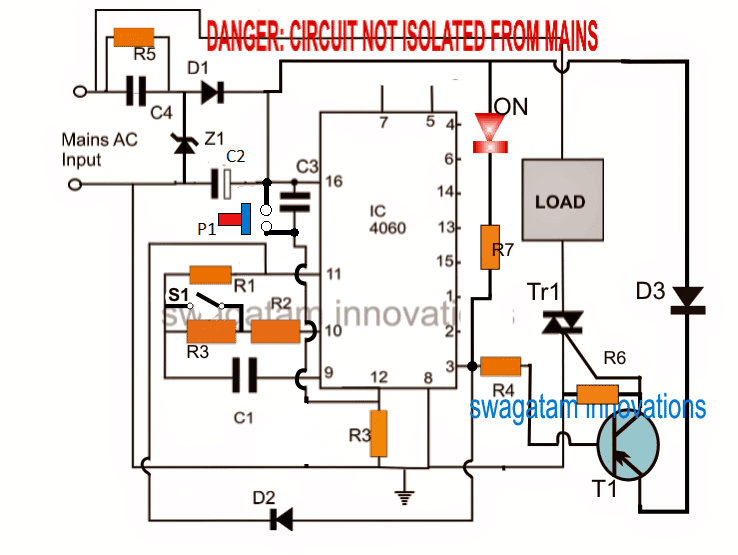
The Design
The requested idea can be easily implemented by using the circuit as shown above.
The proposed idea of a water heater timer circuit may be understood with the help of the following points:
The IC 4060 becomes the main time delay generator component, and is configured as a one shot monostable timer circuit.
Circuit Operation
When power is switched ON, the IC resets to zero via C3 and initiates the counting process.
While the IC is counting, its pin#3 maintains a logic zero or zero volts which keeps the PNP T1 switched ON.
With T1 switched ON, TR1 is also switched ON, and the load which is a water heater or a geyser here gets activated.
Once the set time period elapses, the IC instantly reverts its pin#3 low logic with a high logic, shutting off the triac and the connected water heater.
This high logic is also transferred to pin#11 of the IC via D2 such the the IC counting freezes in this position and the situation latches, for so long until either power is switched OFF and switched ON again, or P1 is momentarily pressed and released.
R2, R3 determine the two selectable time delay options, which decide for how along the load may be kept switched ON, along with R2/R3, the capacitor C1 also directly determines the time delay period in conjunction with R2 and R3.
The entire circuit is powered through a compact transformerless power supply, however this also implies that each and every point within the circuit may be floating at mains AC level and involve lethal electric shock, therefore due care must be exercised while testing the circuit.
Time Delay Formula
The formula for determining the timing components R3 and C1 values is:
f(osc) = 1 / 2.3 x Rt x Ct
2.3 is a constant and will remain as is
The output of the IC will produce normal time delays only if the selected numbers of the parts satisfy the condition:
Rt << R2 and R2 x C2 << Rt x Ct.
Parts List
R1 = 1M5
R2, R3 = as per calculations
R4 = 10K
R6, R7 = 1K
R5 and resistor at pin#12 = 1M
C1 = 1uF/25V non-polar
C2 = 470uF/25V
C3 = 0.22uF
C4 = 0.33uF/400V
D1, D2, D3 = 1N4007
Z1 = 12V zener 1 watt
P1 = push to ON
S1 = SPDT switch
T1 = BC557
Triac = BTA41/600V
IC = 4060
LED = red 5mm


Questions & Answers
Peace be upon you.
Please I need an electronic map for Landing Heater using this piece EVL31-050-04
With thanks.al
Thanks for your excellent water heater controller circuit. However, I would like to replace the power supply unit with a transformer. Now my question is that can I replace the triac with a relay without changing the relevant components. Will there be any side effect on the operation of the circuit?
Thanks.
I am Glad you liked it, please see the second circuit from this article, it is a relay based design, as per your requirement. There are no side effect using a relay.
https://www.homemade-circuits.com/simple-adjustable-industrial-timer/
hi swagatam, am a follower of your website and I congratulate you for your helping hand. I request a geyser water heater circuit which uses thermistor to automatic switch
on and off for predetermined temperature (in degrees celcious)
Sir
Please send me circuit diagram for obstacles avoiding robot without microcontroller
Faiyyaz, I'll try to publish it soon
Hi Swagatam,
I am making a digital timer ( with Arduino, RTC, LCD and a Relay), I am Stuck at relay rating
my Water heater is 2000W and 230V
I am guessing I need to choose a relay with atleast 25A or 30A rating
Please suggest
Regards
Amit Jain
Hi Amit,
yes a relay rated with 25amp contact will be just enough to support the hetare coil safely.
dividing 2000 by 220 gives 9 amps so 25 amps is a good margin.