In this post I will talk about 6 easy yet accurate capacitance meter circuits using the ubiquitous IC 555 and many other easily available ICs.
How Capacitors Work
Capacitors are one of the main electronic components which come under the passive component family.
These are extensively used in electronic circuits and virtually no circuit can be built without involving these important parts.
The basic function of a capacitor is to block DC and pass AC or in simple words any voltage which is pulsating in nature will be allowed to pass through a capacitor and any voltage that’s not polarized or in the form of a DC will be blocked by a capacitor through the process of charging.
Another important function of capacitors is storing electricity by way of charging and supplying it back to an attached circuit by the process of discharging.
The above two main functions of capacitors are used for implementing a variety of crucial operations in electronic circuits which enable getting outputs as per the required specifications of the design.
However unlike resistors, capacitors are difficult to measure through ordinary methods.
For example, an ordinary multitester might have many measuring features included like an OHM meter, voltmeter, ammeter, diode tester, hFE tester etc. but might just not have the illusive capacitance measuring feature.
The feature of a capacitance meter or an inductance meter is seen to be available only in high-end type of multimeters which are definitely not cheap and not every new hobbyist might be interested in procuring one.
The circuit discussed here very effectively tackles these issues and shows how to build a simple inexpensive capacitance cum frequency meter which can be built at home by any electronic novice and used for the intended useful application.
1) Circuit Diagram
Our first capacitance meter circuit which uses a single IC 555 can be witnessed below:
How Frequency Works to Detect Capacitance
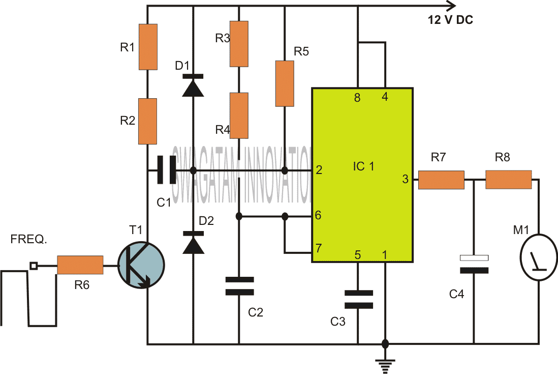
Referring to the figure, the IC 555 forms the heart of the entire configuration.
This work horse versatile chip is configured in its most standard mode that is the monostable multivibrator mode.
Every positive peak of the pulse applied at the input that is pin #2 of the IC creates a stable output with some predetermined fixed period set by the preset P1.
However for every fall in the peak of the pulse, the monostable resets and auto triggers with the next arriving peak.
This generates a kind of an average value at the output of the IC for which is directly proportional to the frequency of the applied clock.
In other words the output of the IC 555 which consists of a few resistors and capacitors integrates the series of pulses to provide a stable average value directly proportional to the applied frequency.
The average value can be easily read or displayed over a moving coil meter connected across the shown points.
So the above reading will give a direct reading of the frequency, so we have a neat looking frequency meter at our disposal.
Using Frequency to Measure Capacitance
Now looking at the next figure below we can clearly see that by adding an external frequency generator (IC 555 astable) to the previous circuit, it becomes possible to make the meter interpret the values of a capacitor across the indicated points, because this capacitor directly affects or is proportional to the frequency of the clock circuit.
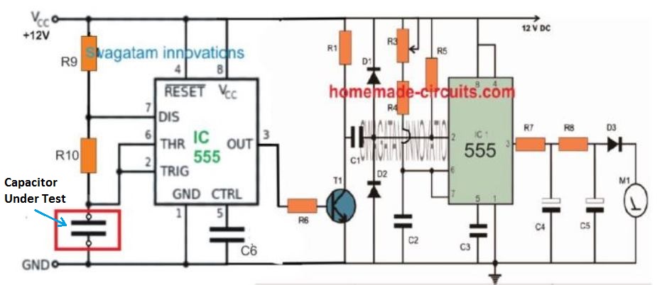
Therefore, the net frequency value now shown at the output will correspond to the value of the capacitor connected across the above discussed points.
That means now we have a two in one circuit which can measure capacitance as well as frequency, using just a couple of ICs and some casual electronic parts. With little modifications the circuit can be easily used as a tachometer or as RPM counter equipment.
Parts List
- R1 = 4K7
- R3 = CAN BE VARIABLE 100K POT
- R4 = 3K3,
- R5 = 10K,
- R6 = 1K,
- R7 1K,
- R8 = 10K,
- R9, R10 = 100K,
- C1 = 1uF/25V,
- C2, C3, C6 = 100n,
- C4 = 33uF/25V,
- C5 = 2.2uF/25V,
- T1 = BC547
- IC1, IC2 = 555,
- M1 = 1V FSD meter,
- D1,D2 = 1N4148
2) Capacitance Meter using IC 74121
This second simple capacitance meter circuit provides 14 linearly calibrated capacitance measuring ranges, from 5 pF to 15 uF FSD. S1 is employed as a range switch, and operates in collaboration with S4 (s1/x10) and S3 (x l) or S2 (x3). The IC 7413 operates like an astable oscillator, together with R1 and C1 to C6 which act like the frequency determining elements.
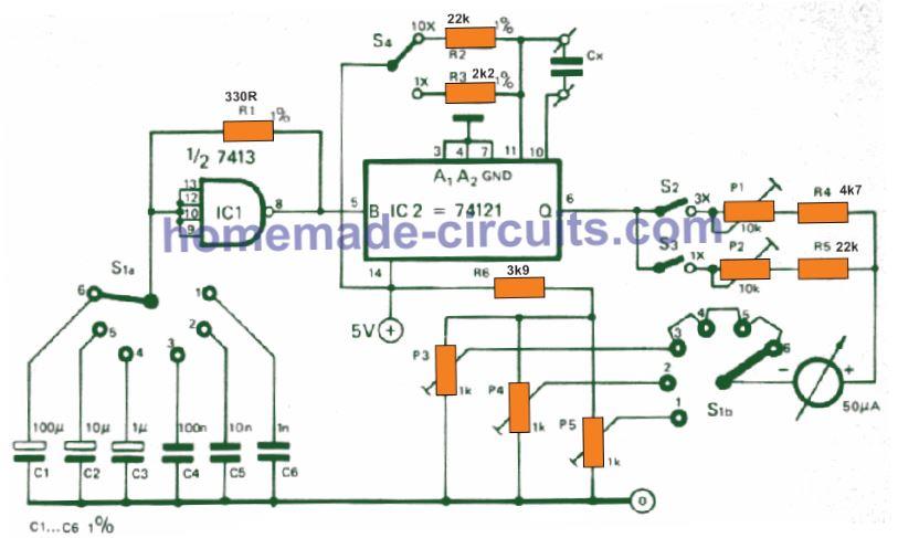
This stage activates the IC 74121 (a monostable multivibrator) so that it generates an asymmetric square wave with a recurring frequency whse value is decided by the parts R1 and C1 to C6 and with a duty cycle as decided by R2 (or R3) and Cx.
The typical value of this square -wave voltage changes linearly as the duty cycle is changed, which in turn modifies linearly based on the value of Cx, the value of R2/R3 and the frequency (established by the S1 switch position).
The final range selector switches S3 (1x) and S2 (3x) basically insert a resistor in series with the meter.
The configuration around the pins 10 and pin 11 of the IC 74121, and for the Cx must be as short and stiff as is feasible, to ensure that stray capacitance here is minimal and without fluctuations.
P5 and P4 are employed for independent zero calibration for low capacitance ranges. For all higher ranges, calibration done by oreset P3 is just sufficient. F.s.d. calibration is rather straightforward.
Do not initially solder C6 in circuit rather attach it over the terminals marked Cx for the unknown capacitor. Put S1 in position 3, S4 in position x1 and S2 closed (s3); this gets set up for the ranges of 1500 pF f.s.d.
Now, C6 becomes ready to be applied as a calibration bench mark value. Next, pot P1 is tweaked until the meter deciphers 2/3 of f.s.d.
Then, S4 could be moved to position 'x 10', S2 held open and S3 is closed (x1 ); this compares to 5000 pF f.s.d., while working with C6 as the unknown capacitor.
The result for these complete set up should provide 1/5 of fs.d.
On the other hand you can procure an assortment of accurately known capacitors and use these across the Cx points and then adjust the various pots for fixing the calibrations on the meter dial appropriately.
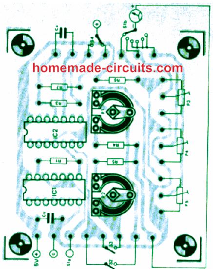
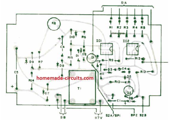
PCB Design
3) Another Simple Yet Accurate Capacitance Meter Circuit
The working of the third capacitance meter circuit can be understood from the following explanation:
When a constant-voltage is applied to a capacitor through a resistor, the capacitor charge increases in an exponential manner.
But if the supply across a capacitor is from a constant current source, the charge on the capacitor exhibits an increases that is pretty much linear.
This principle in which a capacitor is charged linearly is used here in the below discussed simple capacitance meter. It is designed to measure capacitor values well beyond the range of many similar analogue meters.
Using a constant-current supply, the meter establishes the time it requires to complement the charge over the unknown capacitor to some known reference voltage.
The meter provides 5 full-scale ranges of 1,10, 100, 1000, and 10,000 µF. On the 1-µF scale, capacitance values as tiny as 0.01 µF could be measured without difficulty.
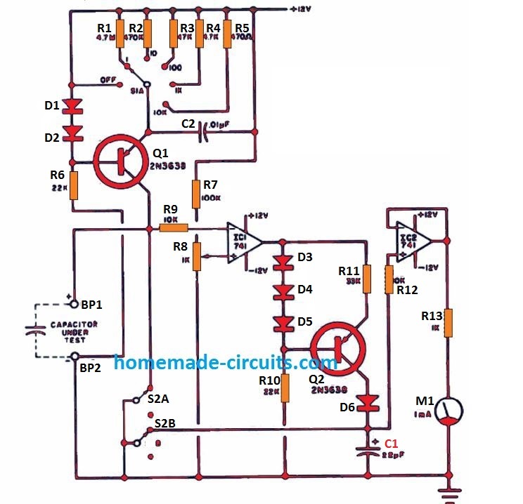
How It Works.
As displayed in Figure, parts D1, D2, R6, Q1 and one of the resistors across R1 to R5 provide 5 selection for the constant current supply through the switch S1A.
When S2 is held in the indicated position, this constant current is shorted to ground through S2A.
When S2 is switched in the alternate selection, the constant-current is driven into the capacitor under test, across BP1 and BP2, which forces the capacitor charge in the linear mode.
Op amp IC1 is attached like a comparator, with its (+) input pin attached to R8, which fixes the reference voltage level.
As soon as the linearly increasing charge across the capacitor under test, reaches a few millivolts higher than (-) input pin of IC1, it instantly switches the comparator output from +12 volts to -12 volts.
This causes the output of the comparator to activate a constant-current source made using the parts D3, D4, D5, R10, R11, and Q2.
In case if S2A is switched to ground, just as S2B, this results in the shorting of the capacitor C1 terminals, turning the potential across C1 to zero.
With S2 in the open condition, the constant-current pasing via C1 triggers the voltage across C1 to increase in a linear fashion.
When the voltage across the capacitor under test causes the comparator to toggle, results in the diode D6 to turn reverse biased. This action stops C1 from charging any further.
Since the charging of C1 only happens until the point where the comparator output status just changes-over, implies that the voltage developed across it should be directly proportionate to the capacitance value of the unknown capacitor.
To ensure that the C1 does not discharge while meter M1 measures its voltage, a high-impedance buffer stage, created using IC2, is incorporated for the meter M1.
Resistor R13 and meter M1 constitute a basic voltmeter monitor of around 1 V FSD. When needed, a remote voltmeter could be employed provided that it features a full-scale range of under 8 volts.
In case you incorporate this kind of external meter, make sure to set R8 on the 1-µF range, so that an accurately identified 1-µF capacitor corresponds to a 1 volt reading.)
Capacitor C2 is utilized to counteract oscillation of the Q1 constant-current supply, and R9 and R12 are employed to guard the op amps in the event the supply DC is switched off during the time when the capacitor under test and C1 are being charged, or else they could start discharging through the op amps, leading to a damage.
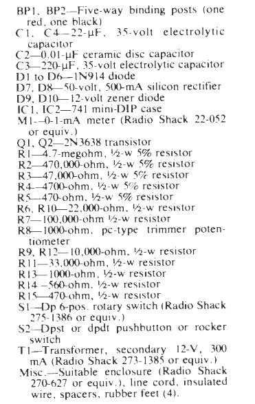
Parts List
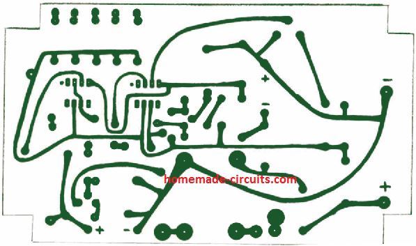
PCB Designs
How to Calibrate
Prior to supplying power to the capacitance meter circuit, use a fine screwdriver to adjust the meter M1 needle precisely to the zero level.
Position an accurately known capacitor around 0.5 and 1.0 µF at +/-5%. This would function as the "calibration bench mark."
Hook up this capacitor across BP1 and BP2 (positive side to BP1). Adjust the range switch S1 to the "1" placement (meter should display 1-µF full scale).
Position S2 to disconnect the ground lead from the two circuits (Q1 collector and Cl). The M1 meter will now begin an upscale movement and settle at a specific reading. Toggling S2 back must result in the meter to fall downward at the zero volt mark. Change S2 once more and confirm the upscale reading of the meter.
Alternatively jump S2 and fine-tune R8 until you find the meter showing the precise value of the 5% of the capacitor's calibration. The above just one calibration set-up will be quite sufficient for the remaining ranges.
4) Capacitance Meter Circuit using IC 74HC132
The fourth capacitance meter design using IC 74HC132 is I have explained below:
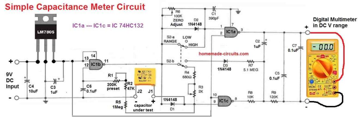
Whenever the aforementioned circuit is linked to an unknown capacitor and a DMM, a DC voltage is supplied to the DMM. The output that follows shows the capacitance value on the DMM.
The DMM reading won't, however, directly display pF or uF. In accordance with the range that the circuit is adjusted to, it will only provide a value for you to understand (the circuit has two ranges for the selections).
How to Calibrate
You will require a 1000-pF and a 1uF capacitor to calibrate the circuit. As much as feasible, choose calibration capacitors whose values you have precisely measured.
Hookup PL1 and PL2 to the 2 volt scale on the DMM. Next, move S2 to the Low position and tweak R6 until the voltmeter registers zero. Attach the 1000-pF capacitor to the terminals "capacitor under test" and set R1 such that a reading of 1 volt appears on the DMM.
After this, insert the 1uF capacitor to the "capacitor under test" terminals and turn S2 to the HIGH position.
Next, tweak potentiometer R3 so that it reads 1 volts on the DMM.
As soon as calibrated, the capacitance tester circuit can be used in the above identical manner to measure capacitors of unspecified values.
Plug the circuit output to your DMM and shift the range of the metre to the 2 volt range. Whenever a capacitor is connected to J1 and J2, the DMM's screen will display micro-farads in the "low range" and picofarads in the "high range".
5) Capacitance Meter Circuit using IC LM358
If you have the IC LM358 in your junk box, then you can easily build the following simple looking capacitance meter circuit, which is our 5th design in the list.
IC1a and its surrounding elements collaborate harmoniously to constitute an oscillator with the ability to generate a square wave output oscillating approximately at 8KHz.
This frequency can be fine-tuned through the utilization of RV1. A standout feature of the LM358 resides in its output capability, which remains undisturbed even when it drops down to the negative supply rail.
Nonetheless, the IC lacks the inherent capacity to pull the output down to an extent where it aligns with the negative supply rail.
This is where an external resistor, designated as R5, enters the picture, playing an indispensable role in achieving this functionality.
Meanwhile, R6 serves a dual purpose within this circuit configuration. It not only stands as an equivalent to R1, as depicted in Fig 2b, but also undertakes the role of a ballast resistor for the zener diode, D1.
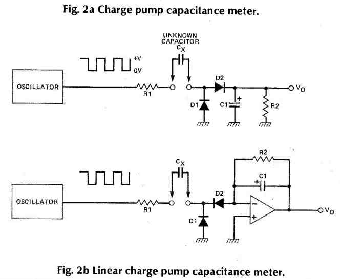
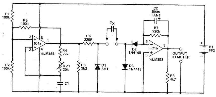
Speaking of D1, it performs the function of clipping the output of IC1a around the 5V mark, effectively resulting in a square wave of unchanging amplitude.
During phases of elevated outputs from IC1a, D3 is tasked with maintaining the 'right-hand' plate of Cx at the negative supply voltage.
Simultaneously, D2 plays a pivotal part in permitting Cx to draw current from the virtual earth situated at IC1 pin 6, exclusively when the IC1a output switches to a low state.
The ingenious current-to-voltage conversion mechanism revolving around IC1b makes optimal use of another valuable characteristic attributed to the LM358.
This operational amplifier remains within the linear mode, even if one or both of its inputs are exposed to the negative supply voltage.
As a direct consequence, pin 5 can be seamlessly linked to the negative supply, culminating in a circuit layout characterized by a scarcity of passive components.
The contribution of R7 comes into play by engendering a voltage at the output of IC1b. This voltage, in turn, exhibits a direct proportionality to the current being drawn from pin 6.
The incorporation of C2 in this context serves to iron out any fluctuations in the system, ensuring that the voltage across R7 mirrors the average current.
R8, once more, makes an appearance in the design to exert a downward pull on the output of IC1b, effectively tethering it to the negative supply.
This strategic arrangement enables the meter to register a zero reading when no capacitor is connected to the system, thereby enhancing the circuit's overall utility.
6) Multi-range Capacitance Meter Circuit
The purpose of this 6th capacitance meter circuit is to precisely measure capacitors within a range of a few picofarads to ten microfarads using a linear scale that provides forward readings.
The meter is highly sensitive and includes a zero adjustment feature, which is beneficial for eliminating the influence of stray capacitances on the lower measurement ranges.
As a result, the 0 to 100pF range is precisely represented on the scale and does not require any mental calculations.
Moreover, constructing the Capacitance meter circuit is uncomplicated and cost-effective, with the meter M1 being the most expensive component. However, it is possible to utilize a spare or second-hand meter as a suitable alternative.
Available Multiple Ranges
The Capacitance meter circuit offers ten available measurement ranges. These ranges are as follows:
- 0 - 100pF
- 0 - 1nF
- 0 - 10nF
- 0 - 100nF
- 0 - 1 pF
- 0 - 10uF
Basic Theory
The following figure shows the whole setup of this multi-range Capacitance meter.
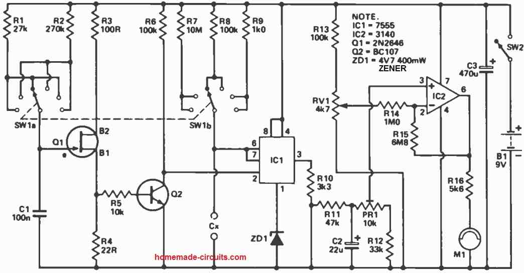
Q1 acts like a pulse maker, creating a short pulse at B2 every three milliseconds (when R1 is picked) or every thirty milliseconds (if R2 is chosen).
These little pulses get bigger and flipped by Q2, which triggers IC1. Each time IC1 is triggered, it makes a pulse.
The length of the pulse changes using the formula T = 1.1 CR.
For instance, if you put SW1 on position three, going with R1, you get pulses every three milliseconds, and R8 is picked.
With a 10n capacitor connected, the pulse lasts: 1.1 x (10 x 10-9) x (100 x 103) = 1.1 x 10⁻³ seconds, or 1.1 milliseconds every three milliseconds.
These pulses are combined to make M1 show the largest possible reading.
Now, if you attach a 100n capacitor and move SW1 to position four, R2 is selected for pulses every thirty milliseconds, and R8 stays selected.
The pulse then lasts: 1.1 x (100 x 10-9) x (100 x 103) = 1.1 x 10⁻² seconds, or 11 milliseconds every thirty milliseconds.
What's cool is that the average voltage remains the same as before, so M1 still shows the full reading. Similar math applies to the other settings.
Circuit Description
Q1, together with its associated components, constitutes a pulse creator that generates a slim pulse every three milliseconds or thirty milliseconds, contingent on the chosen resistor (either R1 or R2).
These pulses undergo magnification and inversion courtesy of Q2 and subsequently serve as triggers for IC1, a 7555 CMOS timer configured as a monostable device.
Each time IC1 gets triggered, it releases a pulse, the breadth of which hinges on the resistor and capacitor values connected to pins 6 and 7.
The resistor is set by SW1b, while the capacitor corresponds to the capacitor to be gauged.
ZD1 assumes the role of pulse modulation, ensuring uniform amplitude for these pulses, while C2 accumulates a voltage determined by both the pulse's duration and frequency from IC1.
This voltage then flows into IC2, forming a voltage amplifier with an approximate amplification factor of eight.
This amplifier is calibrated for maximum deflection via PR1 and integrates a zero adjustment, managed by RV1.
The indicator, meter M1, is deployed to display the voltage generated from IC1's pin 6, thereby reflecting the capacitor's value.
How to Calibrate
For accurate calibration, it is recommended to obtain a capacitor with a tight tolerance.
Alternatively, you can measure a capacitor on a known-accuracy device. Keep this reference capacitor aside for regular checks on the instrument's precision.
With the instrument powered on and the right range chosen, verify the zero setting. Then, connect the test capacitor and cautiously adjust PR1 until the correct reading is obtained.
During prototype testing, it was observed that a change in supply voltage of around one volt causes a 2% increase or decrease in the full-scale reading.
On the 0-100p and 0-1n ranges, meter some readings may appear due to stray capacitances. On these ranges, adjust the zero control counterclockwise until the meter shows zero.
Careless adjustment can lead to errors in subsequent readings. Remember to turn the control fully clockwise when using higher ranges.
Using a marked knob is advisable so you can check its position visually if needed during measurements.
It might also help to label the front panel with the correct settings for the 100p and 1n ranges. The zero control is handy when measuring short lead capacitors or the sweep of variable capacitors.
Meter Options
When using different meters, you have a variety of options. Adjust R16's value to accommodate the chosen meter.
Connect a capacitor suitable for full-scale deflection to the test terminals and set PR1 to its midpoint. This generates an approximately 5V voltage at IC2 pin 6.
Using Ohm's law with this voltage and the chosen meter's full-scale deflection current, you can calculate R16 as follows:
- Meter sensitivity (e.g., 100µA FSD)
- Internal resistance (e.g., 580Ω)
- Total resistance for 100µA =
- V/I = 5 / (100 x 10-6) = 50kΩ
In this case, the meter's internal resistance is negligible, and a 51kΩ resistor should work for R16.
You can also calibrate the instrument for use with an existing multimeter in a similar manner.
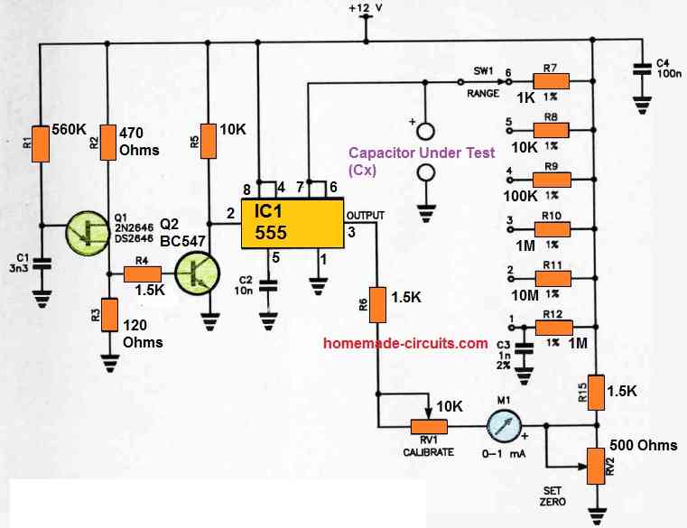
Another Multi-Range Capacitance Meter Circuit using IC 555
It is possible to measure capacitance with a high degree of precision using the below shown multi-range 555 capacitance meter circuit.
The standard panel meter employed here is classified as a class 2.5 type with an accuracy of 2.5%.
As a result, you can gauge capacitors with a level of precision superior to that of most commercially available capacitors.
Q1 functions as a UJT relaxation oscillator, generating brief pulses across R4.
Each pulse activates Q2, causing the collector voltage of Q2 to drop for the pulse's duration, subsequently triggering the 555 timer.
Q1 oscillates at approximately 1 kHz, so the 555 timer is triggered approximately once every millisecond.
During the intervals between trigger pulses, pin 2 of the 555 timer remains in a high state, configuring the internal flip-flop, turning on the internal slave transistor, connecting pin 7 to the ground, and thus, short-circuiting the unknown capacitance, Cx.
The 555 timer's activation eliminates the short circuit across Cx, allowing the capacitor to start charging using the resistor selected by the range switch, SW1.
The value of Cx and the particular range resistor dictate how long this rise lasts after the voltage across Cx starts to climb exponentially, as shown by the following calculation:
t = 1.11 x Rr x C
Where Rr represents the range resistor, at the end of this period, the 555's comparator resets the flip-flop, leading to the activation of the internal slave transistor, which in turn discharges Cx.
Subsequently, pin 3 of the 555 once again goes low, initiating the repetition of this cycle each time the 555 is triggered.
Given that the range resistor remains constant, the on:off ratio of the output pulse is determined by the value of Cx. This relationship remains independent of the frequency of oscillation of Q1.
Pin 3 of the 555 drives current through R6, RV1, and the meter, causing the meter to deflect in accordance with the on:off ratio.
The voltage from pin 3, transitioning from low to high, doesn't swing from 0 V to the positive supply rail.
To compensate for this resulting DC offset, the positive end of the meter is raised above ground using the voltage divider consisting of R13-RV2. Consequently, RV2 offers the means for zero-setting the meter.
All of the range resistors are of the 1% type, although 2% types are acceptable. However, 1% types tend to be more readily available.
Position 1 on the range switch is designated for calibration, with C3 serving as a 2% mica or polyester capacitor. This configuration enables the adjustment of RV1 to achieve full-scale deflection on the meter when there is nothing connected to the Cx terminals.
On the range switch, position 2 corresponds to 100 pF full-scale, position 3 represents 1 nF (1000 pF), position 4 signifies 10 nF (0.01u F), position 5 denotes 100 nF (0.1p, F), and position 6 indicates 1p, F full-scale.
The zero-set control is primarily needed for the 100 pF range. It is advisable to keep the connections between the Cx terminals, SW1, and the 555 as short as possible.
If you replace M1 with a 500 microamp meter, the meter will display full-scale deflection for a range of 50 pF to 500 nF (0.5uF).
In the event of using a IC 556, one half of it can serve as a replacement for Q1 and Q2 oscillator stage.


Questions & Answers
good day sir, I have 3 questions about your circuit that uses 555 timers, what is the value of C5? is D3 a simple diode? and the capacitance meter is capable of measuring from 100 to 1000 microfarads? Thanks for your attention and greetings from CD. juarez.
Thank you Fernando, C5 can be a 2.2uF/25V capacitor, D3 can be a ordinary 1N4148 diode. This circuit will not measure above 100uF/25V, but it will measure all capacitors below this value.
Good day engineer, I really appreciate your answer and I wish you success in your projects, I have a question about your circuit that uses the 741 opam circuits, the switches S2A and S2B must be closed or open for the reading of the capacitor? this circuit if it has the range that I need to measure, thanks.
Thank you Fernando, any one of the switches, either S2 or S3 must be closed, depending on the selected range by the switch S1a
good day engineer, I put together your circuit that uses the 741 ic’s and it doesn’t work for me, I made the connections as they are in the diagram when I turn it on and it gives me a voltage of 8 volts, when activating S2A and S2B the circuit responds like you it mentions the voltage rises or falls to 0 volts but it does not measure the capacitor, the 1k potentiometer does not move the reading, I have checked and I have not connected anything wrong, the transistors are equivalent to the 2N2905A as well as the 1N4148 diodes, do not use the other ranges only for a range from 100 to 1000 microfarads (with the 4.7k resistance to the emitter of Q1) what could I be doing wrong? Thanks a lot
Hi, the circuit using IC 74121 is quite complex and elaborate, so it can be difficult for me to troubleshoot the fault in your circuit. Are you getting a varying frequency at the output of IC1 when you adjust S1a? Please confirm this….there are actually many steps and stages in the design that needs to confirmed and tested, which I cannot do without verifying your circuit practically.
I think you should try the second design which is much easier and a tested design by me.
hello engineer, unfortunately I don’t have a frequency meter to verify the output of IC1, this circuit caught my attention since it can measure capacitance from 100 to 1000 microfarads, which is the range I need, in another message I had asked if the second circuit is the ic’s 555 could also measure that range and you said no, finally, is there any modification to the second circuit so that it can measure that capacitance? Thank you for your attention.
Hello Fernando, if you can measure capacitors upto 1000uF then that is great! However, none of the above circuits are capable of measuring capacitors above 1000uF, and there’s no way to modify them since these are analogue circuits and have limitations, beyond which they cannot operate.
Thank, for the service you are providing.
I only wish you were there while I was working my way through my work life.
Really enjoy your help to others.
I’m an older Electronics tech ( 82 ) still interested in electronics and many other things. Best Regards
Walt Sommers
Thanks Walt, I appreciate your thoughts very much. I too would have surely enjoyed your company! Please keep up the good work!
Hi sir,
Do you supply kit (pcb and components) for yours 555 based Capacitance meter?
Hi Aruli, sorry I do not supply kits, but I can show a practical demo of a working circuit soon..
Sir 33ohms or 33k? Do you have printout of circuit I mean as it should become on board? Thks.
which part are you referring to?
Hi Swag thks for response. I was going to build Brighthub circuit but noticed it’s a bit different. This circuit is more modern? Do you have a pcb for it? Thks.
You are welcome Andrew, I am sorry I do not have a PCB design for this, I wish I could do it for you, however due to lack of time I am not able to do it at the moment…
Hi Swag ok I did this circuit. The thing is that I using a volume audio meter don’t know if this is good? Cause when I tried it nothing came.
Andrew, the recommended meter is 0-1V FSD moving coil meter, not sure how other meters might work…. this circuit has been thoroughly tested by me.
Sir, I want to ask you that can I replace fsd meter with seven segment display? If yes how can I do that . can you please tell me procedure… Thanks
Abhishek, a digital meter might not work properly in the above design, only a moving coil type meter is recommended.
IS 1V FSD METER MEANS 0-1 VOLT DC VOLTMETER OR AC VOLTMETER?
it's 0 to 1V DC
hi
Swagatam can digital multi-meter be use in place of the FSD meter and then tune the selection to DC voltage….thank you…
I am sorry a DMM will not work correctly, because the output could be in a continuously vibrating mode which may be efficiently countered only by a moving coil meter
Dear Mr Swagatam,
Do you have a schematic about ESR meter. Technicians recommend me to check the electrolytic first everytime I come up with a dead circuit, But I dont know how to measure it. Thank you in advance for your answer.
Dear Imanul, presently I do not have it in my blog, but will possibly design it and publish it soon for your reference.
I need some clarity on the resister values, you have 4K7 and 4E7, is this 47K and 47 ohm?
4k7 = 4.7K ohms
4E7 = 4.7 ohms
Hello sir,
1v fsd meter is not available in my area but 6v or up to 6 v fsd are available.Have u any alternate working idea by using another ones.pls help us.
hello Tanmay,
1V is the recommended one, for other higher voltages you may need to reduce R7/R8 proportionately for getting the deflections.
Hello sir, will deflection shows for almost ranges of pF, nF, uF,…..
Another: sir may u pls reffer about components in above diag. mainly upon which quantity of deflection depends?
Hello Ramkumar, the range will need to be calibrated by appropriately setting or selecting the value of R3.
please refer to the following article to know more details about the components and the functioning:
easy-electronic-circuits.blogspot.in/2014/02/simple-tachometer-circuit-or-revolution.html
FSD meter is not showing any deflection. Voltage at FSD meter is 2.2 mV. Voltage at unknown capacitance 7.8 mV. What is the range of this capacitance meter ?
sorry, no digital multimeters will not work here….
Greetings
Can i use my multimeter instead of M1?
I have provided the solution in the previous comment.
dear sir,
i try to make this circuit in practical . but fails to get any output deflection on fsd when capacitance is applied. please tell me how to rectify the problem.
i am getting 2.2 mv in at FSD and 7.8 mV at unknown capacitance side.
please tell me the range of above meter also.
please reply soon.
I am struck.
try different value capacitors and try to find the corresponding full scale range of the meter, you can also take the help of R3 by adjusting it to locate the range of the meter which corresponds to the capacitor value.
yes nF can be measured with this meter, according to me only moving coil type meters will work correctly here, i am not sure about DMMs.
I am using digital multimeter for this. As i want to know the correct of voltage output.
I am getting output but its showing me almost same value for most of the different capacitor.
I want to mesure nF capacitance can it be possible with your circuit?
which meter have you used at the output? you must use a 0-1V FSD moving coil type meter.
The frequency range is 10Hz to 10kHz
You can send the pictures to my iD hitman2008@live.in
Sir,
I cant find the solution. its not working. R3 didn't help me.
i wanna share my circuit photograph with you. Please suggest some other option for rectifying my problem. I am using voltmeter as FSD meter.
What is the range of this circuit.
Give me another alternative to talk to you for rectifyng my problem.
i will be highly obiliged.
thank you for your prompt respose.
Renu
Dear Renu,
Use a 100k pot in place of R3 and adjust it for calibrating the scale of the connected meter. I have tested this circuit and it worked well for me.
Dear Sir,can I use this circuit for as like oscillator meter ? Thank you sir.
Dear Debashees, what's an oscillator meter?? Did you mean frequency meter?
Thank you very much sir, but how will i know about your newly posted article ? Where should i have to search ??
I request you to construct a one having range of 1 to tens or hundreds of Mhz with seletable frequency ranges using common ics such as CD4040,4017,555 etc but excluding the use of programmable chips. The circuit should also be capable of measuring accurate frequencies. I am requesting such an accuracy since i have faced slight to serious variations of known frequency levels ( which may have occured due to variations in the duty cycle of the waves, inability to detect high voltage peaks of the signal by the ics due to poor signal conditioning etc. )
Hello Nazriya, I'll inform you under this comment itself as soon as it gets posted, yes it will be very accurate.
Sir could you please suggest a suitable frequency divider circuit which can be used in corporation with a digital fequency meter ( which is capable of measuring a maximum of 999 Hz )to measure upto tens or hundreds of MHz by caliberations.
The divider should have this range
f/10 to f/10,000 indicated by respective frequency ratio switches
Nazriya, yes it can be done either by using many 4017 ICs or a few 4040 ICs. I'll try to post a related article possibly soon in my blog.
Sir i have tested the basic circuit diagram without connecting any galvanometer or binary indicator. On measuring voltages by feeding a 1 Khz wave, i got approx. 0.12 avg. Voltage. On feeding 10 Khz i got 0.4V etc. I understood that voltage increases on increase in freq. But the problem is , very small voltages in small frequency. Actually i want to make such a frequency meter which can be used to measure atleast 50 hz and therefore can be used for the testing at various construction steps of inverter like projects. I don' t need a one with LED displays. I am interested in implementing the above circuit with IC LM3914 but what to do at that lowest voltage levels???? Will U PLZ HELP ME????
Nazriya, the above circuit can be used to measure right from 10Hz to 10kHz….you will have to adjust R4/R5 also appropriately for the different ranges of the frequencies…the circuit will not work with a single setting for all the ranges as is true for even highly sophisticated instruments.
By the way the LM3914 just needs 1 to 5V as input for providing the desired output display, in fact you can tweak the input preset of the LM3914 even to sense voltages as low as 0.2V