In this post I have explained how to use IC 555 to create 7 interesting siren and alarm sound effect generator circuits.
The versatile astable multivbrator configuration of IC 555 allows us to implement it for making various types of sirens and alarm circuits.
This becomes possible because an astable is basically a waveform generator, and can be customized for generating different types of sound waveforms, resembling alarm and sirens sounds.
What we will Learn
Here I have explained how to build the following siren and alarm circuits using IC 555:
- Monotone Alarm
- Pulsed Alarm
- Warble He-Haw Siren
- Police Siren
- Red Alert Star-Trek Alarm
- Destroyer Whooper Siren
- Ambulance Siren
1) Monotone Alarm
In the first figure below we can see the IC 555 configured as a 800 Hz frequency monotone alarm circuit.
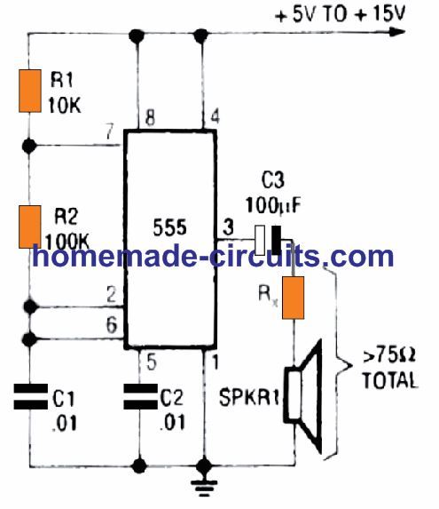
The speaker can have any impedance value, due to the presence of the current limiting resistance Rx. A safe value could be around 70 Ohms 1 watt.
For making a high power continuous tone alarm circuit we cam upgrade the above circuit through a power transistor driver Q1 and a more powerful loudspeaker, as shown below:
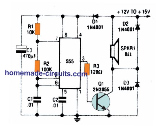
Since the design may produce a high level of ripple voltage, D1 and C3 are included to prevent the ripple interference with the IC 555 functioning.
Diodes D2 and D3 are included to neutralize the inductive switching spikes generated from the speaker coil, and to safeguard the transistor Q1 against damage.
Formulas and Calculations
Oscillation Frequency Formula:
The output frequency of the 555 timer in astable mode is given by:
f = 1.44 / ((R1 + 2 * R2) * C1)
Duty Cycle Formula:
Duty cycle (D) is the percentage of the high time (Thigh) with respect to the total period (T).
- Thigh = 0.693 * (R1 + R2) * C1
- Tlow = 0.693 * R2 * C1
- T = Thigh + Tlow
- D = (Thigh / T) × 100
Component Values:
- R1 = 10 kΩ
- R2 = 100 kΩ
- C1 = 0.01 µF
Frequency Calculation:
Substituting the values into the frequency formula:
- f = 1.44 / ((10 k + 2 * 100 k) 0.01 µF)
- = 1.44 / ((10,000 + 200,000) * 0.01 * 10⁻⁶)
- = 1.44 / (2.1 * 10⁻³)
- f = 685.7 Hz
The alarm tone frequency is approximately 686 Hz.
Duty Cycle Calculation:
High time (Thigh):
- Thigh = 0.693 * (R1 + R2) * C1
- = 0.693 * (10 k + 100 k) * 0.01 µF
- = 0.693 * 110,000 * 0.01 * 10⁻⁶
- Thigh = 0.0007623 s (or 762.3 µs)
Low time (Tlow):
- Tlow = 0.693 * R2 * C1
- = 0.693 * 100,000 * 0.01 * 10⁻⁶
- Tlow = 0.000693 s (or 693 µs)
Total time (T):
- T = Thigh + Tlow
- T = 0.0007623 + 0.000693
- T = 0.0014553 s
Duty cycle (D):
- D = (Thigh / T) * 100
- D = (0.0007623 / 0.0014553) * 100
- D = 52.37%
The duty cycle is approximately 52%.
2) Pulsed IC 555 Alarm Circuit
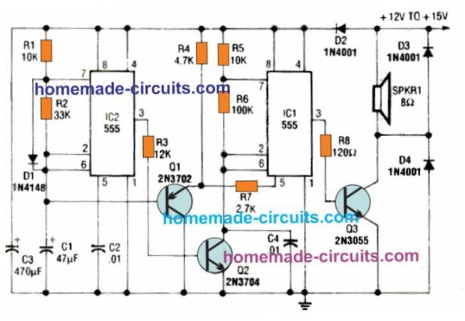
The previous 800 Hz monotone alarm could be converted into a more interesting pulsed 800 Hz alarm by adding another astable multivibrator with the tone generator circuit as shown in the second concept below.
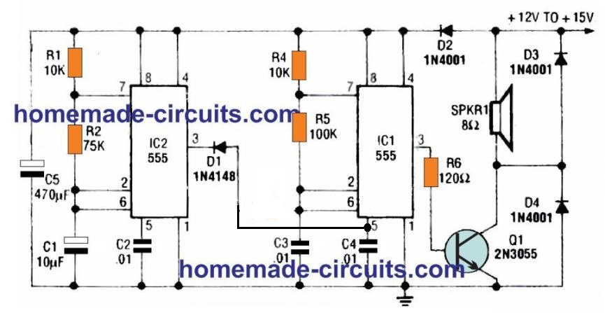
We have already studied how pin 5 can be used for controlling the pulse width of the IC 555.
Here IC 2 is configured as a 1 Hz oscillator circuit which causes pin 5 of IC 1 to alternately become low at a 1 Hz rate. This in turn causes pin 3 800 Hz pulse width to narrow to an extent which almost turns OFF Q1. This produces a 1Hz sharp pulsed alarm effect on the loudspeaker.
3) Warble He-Haw Alarm Siren Circuit
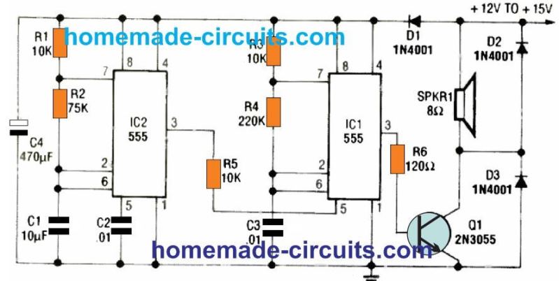
If you want to convert the previous design into an ear piercing warble alarm, you can do it by simply replacing the D1 diode with a 10 K resistor as revealed in the above diagram. Also known as he-haw alarm, these are commonly used in European emergency vehicles.
We know that pin 5 can be used with an external high/low signal for modulating the pin 3 output with a corresponding widening/narrowing pulse widths. The 1 Hz alternate high low supply at pin 5 of IC2 forces the output pin #3 voltage of IC 1 to generate a symmetrically changing frequency varying from 500 Hz to 440 Hz. This causes the speaker to generate the required sharp high volume warble alarm sound at 1 Hz rate.
Calculating the Part Values
IC2 Frequency Calculation (Slower Frequency Oscillator)
The frequency of an NE555 in astable mode is given by:
f = 1.44 / [(R1 + 2R2) * C1]
- R1 = 10 kΩ
- R2 = 75 kΩ
- C1 = 10 µF
Substitute the values:
f = 1.44 / [(10,000 + 2 * 75,000) * 10 * 10⁻⁶]
f = 1.44 / [160,000 * 10 * 10⁻⁶]
f = 1.44 / 1.6
f ≈ 0.9 Hz
So IC2 generates a frequency of approximately 0.9 Hz (a slower oscillation).
IC1 Frequency Calculation (Higher Frequency Oscillator)
The frequency for IC1 (another astable NE555) is calculated similarly:
f = 1.44 / [(R4 + 2R5) * C2]
- R4 = 220 kΩ
- R5 = 10 kΩ
- C2 = 0.01 µF
Substituting the values:
f = 1.44 / [(220,000 + 2 * 10,000) * 0.01 * 10⁻⁶]
f = 1.44 / [240,000 * 0.01 * 10⁻⁶]
f = 600 Hz
So IC1 generates a frequency of approximately 600 Hz.
Interaction Between IC2 and IC1
The output of IC1 (600 Hz) is modulated by the IC2 (0.9 Hz) to create the "he-haw" effect. This results in alternating bursts of sound.
Q1 Transistor and Speaker Driver
Q1 (2N3055) amplifies the modulated signal to drive the speaker. Its base current is determined by R6:
Ibase = (Vout - Vbe) / R6
Where:
- Vout ≈ 11V (NE555 high output)
- Vbe = 0.7V (base-emitter voltage of Q1)
- R6 = 120 Ω
Substituting the values:
Ibase = (11 - 0.7) / 120
Ibase ≈ 85 mA
The transistor amplifies this base current to supply sufficient current to the speaker.
Power Dissipation in Q1
The power dissipated in Q1 is given by:
P = VCE × IC
Where:
- VCE is the collector-emitter voltage.
- IC is the current through the speaker.
4) Making a Police Siren
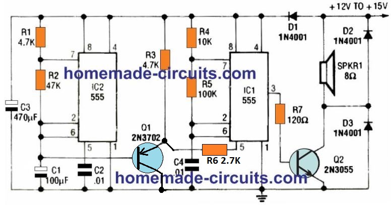
The IC 555 can be also used for making a perfectly imitating police siren circuit as demonstrated above.
This fourth circuit is designed to produce the typical wailing sound commonly heard in police sirens.
Here IC2 is connected as a low frequency oscillator with a frequency set at a 6 second ON OFF rate.
The slow exponential triangle wave ramp generated across its C1 is fed at the base of Q1 configured as an emitter follower.
The frequency of IC1 is set at 500 Hz which becomes its center frequency.
The slow rising and falling ramp at base of Q1 follows at its emitter and modulates pin 5 of IC1. The slow ramp causes alternate cycles of slow rising voltage for 3 seconds, and slow decaying voltage for the 3 seconds on pin 5. Due to this pin 3 frequency and PWM also modulates accordingly generating the wailing police siren sound effect.
Part Value Calculations for the Police Siren
IC2: Low-Frequency Oscillator
IC2 generates a low-frequency signal that modulates the second 555 timer (IC1).
Frequency Formula:
f = 1.44 / ((R1 + 2 * R2) * C1)
Given Values:
- R1 = 4.7 kOhms,
- R2 = 470 kOhms,
- C1 = 100 uF
Substituting we get:
- f = 1.44 / ((4.7 k + 2 * 470 k) * 100 uF)
- = 1.44 / ((4,700 + 940,000) * 100 * 10^-6)
- = 1.44 / 0.09447
- f ≈ 15.24 Hz
The low-frequency output from IC2 is approximately 15 Hz.
IC1: Audio Oscillator
IC1 generates the siren audio signal. Its frequency is modulated by the output of IC2.
Frequency Formula:
f = 1.44 / ((R4 + 2 * R5) * C2)
Given Values:
- R4 = 10 kOhms,
- R5 = 100 kOhms,
- C2 = 100 uF
Substituting we get:
- f = 1.44 / ((10 k + 2 * 100 k) * 100 uF)
- = 1.44 / ((10,000 + 200,000) * 100 * 10^-6)
- = 1.44 / 0.021
- f ≈ 68.57 Hz
The audio output frequency from IC1 is approximately 69 Hz which is modulated by the 15 Hz signal from IC2.
Speaker (SPKR1) and Output Power
SPKR1 = 8 Ohms (minimum load impedance).
The output voltage across the speaker is dependent on the supply voltage.
The current through the speaker can be approximated as:
I = V / Rspeaker where V is the peak voltage.
If V = 12 V:
I = 12 / 8 = 1.5 A
The power delivered to the speaker:
P = I2 * R
P = (1.5)2 * 8 = 18 W
5) Red Alert Star Trek Alarm Circuit
The fifth circuit in the list is another very interesting sound effect generator using the IC 555 astable. It is the red-alert alarm sound generator, also called the star trek siren due to its frequent use in the popular TV series star trek.
Typically, the red alert alarm sound initiates with a low frequency tone, that rises to a high frequency note within a quick span of around 1.15 seconds, and cuts off for 0.35 seconds, and again rises from a low to high frequency, and the cycle continues giving rise to the star trek red-alert alarm sound.
Just like the previous alarm and siren sound circuits, this circuit also keeps repeating the sequence as long as it remains powered.
The IC 2 here is configured as a non symmetrical oscillator circuit. The capacitor C1 is alternately charged through the elements R1 and D1, and is alternately discharged through R2.
This produces a quick rising and fading sawtooth pluses across the capacitor C1. This ramping signal is buffered by the emitter follower and applied as a modulating voltage to the control input pin 5 of IC1 via R7.
Due to the sawtooth nature this waveform causes the pin 3 output frequency of IC1 to gradually rise for the slow decaying portion of the waveform, and then quickly drops during the collapsing part of the waveform.
During each of the decaying section of the waveform cycle, the corresponding rectangular pulse from pin 3 of IC2 instantly switches OFF Q2, which in turn causes pin2 of IC2 to go low.
This interrupts the C2 output and the rising tone on the speaker, giving rise to the peculiar red alert star trek alarm sound effect.
6) Destroyer Whooper Siren
Have you seen those good old WWII navy movies, where you might have listened to that special "whoop-whoop-whoop" siren sound as a destroyer ship cruised through the ocean waves, with its firearms blasting, and all crew members screaming "battle stations!".
The IC 555 circuit below will create the same distinctive "whooper," siren sound effect and that might cause quite many heads turn.
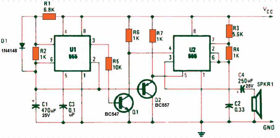
If you actually wish to draw attention of the folks, you can use an amplifier to boost the whooper sound effect. IC U1 is hooked up as a low-frequency asymmetrical oscillator.
Q1 inverts the output signal and supplies it to the reset terminal of U2 at pin 4. IC 555 U2 is wired as an audio oscillator and starts operating as soon as the UI 555 output goes low.
Since the U2 pin 5 constant potential constant, the circuit might only create a "bleeping." sound.
The voltage over capacitor C is applied to the transistor Q2 base, switching it on, which grounds the pin 5 of U2 555.
Once the pin4 reset signal frequency on pin 4 drops, causes the U2 output frequency to increase.
The of U2 555 then starts sounding like the "whoooop", which begins with low frequency tone, and gradually ends with a high ear piercing tone.
Whooper Siren Calculations
U1: Low-Frequency Oscillator (Modulator)
U1 operates in astable mode to generate a low-frequency signal.
Frequency formula for astable mode:
f = 1.44 / ((R1 + 2 * R2) * C1)
Given Values:
- R1 = 6.8 kOhms,
- R2 = 1 kOhm,
- C1 = 470 uF
Substituting we get:
- f = 1.44 / ((6.8 k + 2 * 1 k) * 470 uF)
- = 1.44 / ((6,800 + 2,000) * 470 * 10-6)
- = 1.44 / (8,800 * 470 * 10-6)
- f ≈ 0.34 Hz
The modulating frequency is approximately 0.34 Hz (about 3 seconds per cycle).
U2: Audio Oscillator
U2 also operates in astable mode and generates the audio tone modulated by U1.
Frequency formula for astable mode:
f = 1.44 / ((R3 + 2 * R4) * C2)
Given Values:
- R3 = 5.6 kOhms,
- R4 = 1 kOhm,
- C2 = 0.33 uF
Substituting we get:
- f = 1.44 / ((5.6 k + 2 * 1 k) * 0.33 uF)
- = 1.44 / ((5,600 + 2,000) * 0.33 * 10-6)
- = 1.44 / (7,600 * 0.33 * 10-6)
- f ≈ 579 Hz
The audio output frequency is approximately 579 Hz.
7) IC 555 Ambulance Siren Circuit
The sound produced resembles that of a Victorian-era ambulance siren and is intensified by incorporating components such as C2, C3, Q1, Q2, R1, and R2.
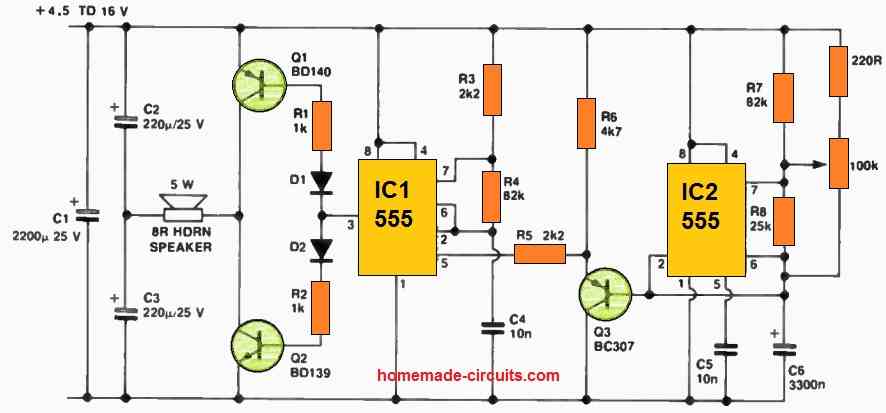
When operated with a 12-volt power source and one or two 8-ohm, 5-watt horn speakers, the output is incredibly loud at close proximity.
Besides the audio output, the only alterations made to the original circuit pertain to both timing sections of the IC 555 timers, which are responsible for generating the required frequency and modulation for the desired sound type.
For added sound modulation variety, R7 can be substituted with a 220-ohm resistor, and R8 can be replaced with a 100k trimpot, with its wiper connected to pin 7 of IC2, as illustrated.
This adjustment transforms the sound from a rapid 'whip-whip' effect in one direction to a 'wow wow' effect in the opposite direction.
The modulation ranges from approximately 6 to 7 Hz to just under 1 Hz before reaching the end of the wiper's travel.
Please note that if this alarm is intended to be used with two speakers and/or a power source exceeding 6 volts, it is crucial to equip Q1 and Q2 with moderate heatsinks.
When two speakers are employed with a power supply ranging from 9 to 16 volts, a more favorable outcome is achieved by replacing C2 and C3 with 470uF capacitors.
Here is a summary of the current consumption at different voltage levels when using 220 pF for C2 and C3, and a single 8-ohm speaker:
- 16 V: 420 mA
- 12 V: 320 mA
- 9 V: 250 mA
- 6 V: 160 mA
- 4.5 V: 100 mA
When two speakers are used, both the current draw and sound output nearly double.
Additionally, it's important to note that C1 is indispensable with any power source as it serves as a power storage element to accommodate the rapid fluctuations in current consumption.
Lastly, please exercise caution and consideration for others when testing and employing this alarm system.
Calculations for Ambulance Siren
IC1: Low-Frequency Oscillator
The frequency of oscillation for IC1 is determined by the components R3, R4, R5, and C4 using the standard astable 555 formula:
Frequency = 1.44 / ((R3 + 2 * R4) * C4)
Substituting the values:
- R3 = 2.2 kΩ
- R4 = 82 kΩ
- R5 = 2.2 kΩ (this has a negligible effect on frequency calculation)
- C4 = 10 nF = 0.01 µF
Frequency = 1.44 / ((2.2 k + 2 * 82 k) * 0.01 µF)
Frequency ≈ 1.44 / (166.2 k * 0.01 µF)
Frequency ≈ 1.44 / 1.662 ms ≈ 867 Hz
IC2: High-Frequency Oscillator
The frequency of oscillation for IC2 is determined by R7, R8, and C5 using the same formula:
Frequency = 1.44 / ((R7 + 2 * R8) * C5)
Substituting the values:
- R7 = 82 kΩ
- R8 = 25 kΩ (adjustable via the 100 kΩ potentiometer)
- C5 = 10 nF = 0.01 µF
For the maximum resistance (R8 = 25 kΩ): Frequency = 1.44 / ((82 k + 2 * 25 k) × 0.01 µF)
Frequency ≈ 1.44 / (132 k × 0.01 µF)
Frequency ≈ 1.44 / 1.32 ms ≈ 1.09 kHz
For the minimum resistance (R8 ≈ 0): Frequency = 1.44 / ((82 k + 0) * 0.01 µF)
Frequency ≈ 1.44 / (82 k * 0.01 µF)
Frequency ≈ 1.44 / 0.82 ms ≈ 1.76 kHz
Modulated Output
The output of IC1 modulates the frequency of IC2 creating an ambulance siren effect. IC1's low-frequency oscillation alternates IC2s pitch between its high and low-frequency limits.
Back to You
Well these were some hints regarding how to use IC 555 for creating useful alarm and siren circuits. Do you have any other interesting sound effect generator using IC 555?
If you do, please provide the details here, we will be most happy to include it in the above list.


Questions & Answers
I came to look for information about a learning circuit that doesn’t work for me; Thank you for your willingness to contribute your knowledge. It is difficult to just explain my circuit without the diagram, it would have to be a photo, I don’t know how to send this type of graphic information.
Sure, I will try to solve your problem….can you please upload your schematic on any online free image hosting site, or Google drive, and send me the link here?
Can I use a TIP120
You can use it…
I also noticed that my 2N3055 is slightly heating up
slightly heating is oK…
Or can we omit the transistor and add a 100uf capacitor in series with the pin 3 of IC1 and the speaker pin
You can do that, but the sound output would be very low.
So is it possible to use a BC547 instead of 2N3055
BC547 will burn if a speaker is used as a load, 2N3055 is good, or you can try TIP122 or TIP31 etc…
Readings are 589Hz. After that I found that the speaker was emitting a low sound, continuous tone and required 7.5V and 70mA. (The tone sounds like the tone of Monotone Alarm).
Yes it will be monotone, until you connect its pin#5 with the pin#3 of the other IC 555.
Adjust the tone to make it louder.
If it is not loud that means driver transistor is not working correctly.
For the variable capacitor??
Capacitor cannot be variable, instead you can try different fixed values…first try with the 22k pot and the existing capacitor.
What potentiometer and variable capacitor is best to use ???
You can try a 22k pot with a 1k series resistor.
Can I use a potentiometer to make a variable R3 and a variable capacitor to represent C3
Yes you can, just make sure R3 pot has a series 1k resistor with it.
If the calculated frequency is 600Hz, won’t it be the loudest possible sound.
That will need to be experimented, you can check the response practically with different output frequencies across the speaker, and check which one produces the loudest sound.
Can I measure the frequency of the output of the speaker, while adjusting R3 and C3 and stop when it reaches 600Hz
You can do that, but checking the sound output will be easier, since you can understand which audio tone sounds the best and the loudest
Now it measures between 61.85 Khz and 33 Khz
As per the calculations it should be 600 Hz, please try adjusting the R3, C3 values until you get an acceptable output tone on the speaker.
I first measured the Hz at the input of the speaker with a multimeter. Readings are oscillating between 49.95Hz and 61.33Hz. After that I found that the speaker was emitting a low sound, continuous tone and required 12.1V and 70mA. (The tone sounds like the tone of Monotone Alarm).After I removed R5 the tone still continued. When the speaker was connected to pin 3 and ground it didn’t emit any sound.
In the he-haw circuit, the IC1 frequency (on speaker) must be around 600 Hz as per the part values and the calculations. Please check it again.
I made the modification (replaced the R5 with a 1K resistor) and powered it through a LM7812.This time it doesn’t click when I give it power, but rather when I connect the 2N3055’s collector to the speaker pin connected with two diodes (Because it can’t be connected to a breadboard properly and I relied on touch contact). My multimeter readings on what power it takes in are 7.5V and 70mA when I connect the 2N3055’s collector to the speaker pin connected with two diodes and when I disconnect the 2N3055’s collector from the speaker pin connected with two diodes, the readings are 12.1V and 40mA
First we have to find out whether the two astables are oscillating or not.
Please disconnect the R5 end from the pin#3 of IC2, and check whether the speaker is generating an tone or not.
(If possible connect pin#5 of IC1 with ground through a 0.01uF capacitor, so that it works like a simple oscillator.)
After this you can also check whether IC2 is oscillating or not by connecting a speaker across its pin#3 and ground.
Sorry Swagatam, it looks like there was a mistake. I had a 30V source and used a cheap 15V Zener diode to regulate it to 15V, but it couldn’t give the needed 70mA to run the circuit. I later used a LM7815 and it works. But the Warble He-Haw Alarm Siren Circuit doesn’t work. The speaker just clicks once at the moment I give it power
No problem Anto,
However, I would recommend using a 12V for the above circuits, using 7812 IC.
In the He-haw circuit please try replacing the R5 resistor with aa 1k resistor, and check the response…
My circuit is not working (Pulsed Alarm Circuit). When I build the circuit and power the circuit with 15V DC, It immediately alerts me that there’s a short circuit even after there is no error in building it.
The circuit diagram is correct, there is no short circuit in the diagram.
I have a cheap decibel meter with a digital read-out and it can output a 5v dc signal for an external alarm. What is the best way to activate one of these circuits while the 5v signal is present? Thanks!
I am assuming the output terminal of your decibel meter has 0V or ground supply during the time it is not supplying the 5V DC, in that case you can try any of the above alarm circuits. Simply disconnect the pin#4 of the IC 555 from the positive line and connect it with your decibel meter’s 5V DC output, that’s all.
Make sure to use a 5V DC to power the IC 555 also.
Hi Sir.
I have two questions.
1) In scheme 2 what is the function of diode D1 and diode D4?
2) What power does transistor Q1 provide? Thank you
Hi Rosario,
D1 is used to ensure that pin#5 of IC1 gets only the ground signal from the IC2, and the positive voltage is blocked. D4 and D3 bypasses the high voltage spikes generated by the speaker and thus safeguards the ICs from the spikes.
Q1 can easily handle up to 20 watts of power
Many thanks
One last question if I may. I have found that making most of these circuits I could omit the loudspeaker and power transistor driver and output the sound across pin 3 of IC1 and ground and then to an amplifier. Are there any precautions I should take such as signal filtering? I also noticed the signal is too strong, can I attenuate it somehow? I would like to get the output signal to a “Line level” so that it can be connected to an audio mixer. Thank you.
Yes, the pin3 can be directly configured with a external amplifier without any issues or modifications. However, just make sure to have a capacitor in series with the pin3 line.
I’ve breadboarded all of these Siren Circuits and they work great, however, I can not for the life of me get that last one (Destroyer Whooper Siren) to work. I’ve tried building it multiple times and verified that all the parts and continuity between them work. If I disconnect Q1’s collector from pin 4 of IC2 then a high pitch wine is heard, otherwise just silence. Any suggestions most appreciated.
That’s amazing, glad you could build all of those successfully.
In the last circuit, probably IC1 keeps IC2 disabled until C1 changes to 2/3rd Vcc, after this IC2 becomes active. IC2 now supplies the intended audio frequency to the speaker….In the meantime as the C1 charge keeps dropping, it generates an exponentially decreasing voltage at pin#5 of IC2 causing the necessary modifications in the output tone, to generate a whoooop like sound.
This goes on until C1 charge drops below 1/3rd, when the IC1 yet again disables IC2 and the speaker shuts off.
Everything seems OK in the diagram, not sure what might be exactly the issue.
After looking it over very carefully, I found that I neglected to wire pin4 of IC1 to Vcc. I’ve been drawing the circuits out on note paper and formatting the schematic in such a way to better understand for myself. I guess some things get lost in translation. I can’t express how relived I am.
Glad you could solve the problem so quickly, such things are quite common while testing or building electronic circuits, and it helps us to learn more!
greetings,
Is it safe to assume that the values of C3 and C4 in the Star Trek circuit are in microfarads?
Thanks!
yes….C3 = 470uF, and C4 = 0.01uF
sorry, *C2, and C4.
yes those are also in uF