In this post we investigate a circuit, designed for implementing an automatic sliding gate or door action, and includes a set of features as specified in the request. The idea was suggested by Mr. Andreas.
Technical Specifications
Can you help me to design a simple sliding gate controller. How can work its like this...Press a switch and open the gate, after a minute the gate close again.
If during the closing someone passing in front of the gate then the gate opens again(with the help of infrared cell??).
Reaching at the end(Stopping) during opening and closing its made by magnetic or limit switch.. Note this system must work on 24V.
Many thanks,
Andreas Christodolou
The Design
The proposed automatic sliding gate controller circuit may be understood as explained in the following points:
Referring to the circuit below, it can be divided into three stages: the set-reset latch using T1/T2, the monostable timer using IC 4060 and the IR interceptor using T3/T5.
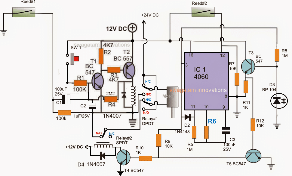
Note:
- Please disconnect the 100k below C1 from the ground, and connect it on C1 positive terminal, meaning the 100k should be connected right across C1 terminals and nowhere else.
- R6 needs to be calculated for getting a 1 minute delay before the gate initiates a reverse closing motion
Let's assume the gate to be in the "closed" position with Reed#2 actuated by the relevant gate magnet.
This ensures pin#12 of the IC 4060 to be rendered high and the IC stays inactive (pin#3 switched OFF).
In the above scenario, the relay#1 is already OFF, with its N/C position closed (because T1/T2 are OFF), and T4 is also OFF due to the absence of a base drive, which implies relay#2 is OFF and in the N/C position.
With relay#2 in N/C, the motor is switched off due to the absence of a positive link via the relay#2 N/O contact.
The entire circuit is thus in a switched OFF condition.
Now, as requested, the opening of the gate is initiated by pressing SW1 momentarily.
Pressing SW1 instantly latches T1/T2 via R4, toggling relay#1 such that its N/O contacts close, which in turn forces the motor to slide the gate towards the "open" direction.
As soon the gate slides away from its "close" position, reed#2 is released, which instantly enables the IC 4060 and it starts counting, with its pin#3 now with a logic zero.
The gate rolls on until it reaches the extreme end when the other relevant magnet fixed on the gate activates reed#1.
On activation, reed#1 pulls the base of T1 to ground via C1, breaking the latch, which in turn deactivates relay#1 and its contacts return to their N/C points.
However relay#2 still being in a switched OFF condition causes the motor to halt due to the absence of power through relay#2 (N/O) points.
In the meantime, IC 4060 completes its counting allowing a high to appear at its pin#3. (the IC now latches in this position via D2)
This immediately activates relay#2, enabling a reverse activation of the motor.
The motor starts sliding the gate towards the "close "position, and the moment it reaches the "close" end, reed#2 is activated yet again. At this position, the IC is again reset causing a no signal at its pin#3, deactivating relay#2 and....shutting off the motor. The circuit reverts to its original standby state.
Calculating the Time Delay
The universal equation for finding the timing component Rt and Ct values is:
f(osc) = 1 / 2.3 x Rt x Ct
2.3 is just a constant with regards to the ICs internal configuration.
Preventing Accidental Entry
As per the request, the circuit needs to respond to an accidental entry of an individual through the gate in the course of its closing process, in order to safeguard the individual and also the gate mechanism.
This is implemented using an infrared transmitter receiver assembly, as shown in the diagram.
D3 is a receiver IR photodiode which is kept switched ON through a perpendicular IR activated transmitter beam, focused on D3, the beam position is supposed to be in a straight line along the gate's sliding action.
As long as D3 stays actuated, T3/T5 are unable to conduct, however in the presence of an individual who may be trying to make a quick entry across the gate while its closing, would in the course obstruct the IR beam, triggering T3/T5 which in turn would conduct and disable T4, and relay#2.
With relay#2 disabled, the door would instantly stop its closing motion and halt on the spot until the individual has completely crossed the restricted line of action.
For the sake of simplicity, a momentary halting of the gate looks more appropriate, instead of enforcing a reverse opening action which might unnecessarily delay the process.
Using a Transistorized Timer Stage
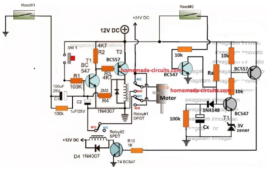
The above could be much simplified by replacing the IC 4060 timer stage with transistorized delay ON timer, and by removing the IR detector stage. The complete circuit diagram could be witnessed below:
The IR Transmitter Stage
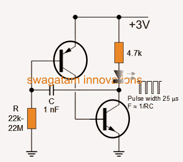
The IR transmitter which is supposed to focus a beam on D3 may be built using the following circuit:



Questions & Answers
sir,
In the first circuit below relay seems to be not connected with diode.
thanks manjunath, you are right, I'll do the correction soon
Dear Swagatam,
i have been waiting for the design of the sliding gate opener circuitry and im very pleased to see it posted today. Im also very glad you have some time for me and dispite your busy days you make it happen !!
Although i have some comments/corrections.
1. The motor its a 5A 220V a.c (Not a 24V d.c.) so i think it needs two relays one for the forward and another one for the reverse direction.
2. As for the IR detection there are ready made transmitter and receiver working either 12 or 24vdc and at the position of D3(BP104) diode can be used the receiver's relay output (have NO/NC) to trigger it instead.
Once again many thanks for your efforts and all the help on this blog.
Andreas
Thanks Andreas, I am glad you liked it.
I am afraid, reversing an AC motor could be a complex affair….so I think a DC motor should be preferred, the voltage rating is not an issue it can be any higher value than 24V.
yes, a ready made IR proximity sensor assembly can be used instead of building one as shown in the diagram
Thanks a lot Swagatam, reversing a single phase motor its the most easiest way, i have done this many times before. Single phace ac motors always have a capacitor with three leads. When you want to reverse its direction all you have to do its to change one of this wires. Then if your not sure refer to motor's connection box. Other than that this ac motor its allready installed and cannot change it.
Thanks Andreas, OK that means that above circuit can be used with an AC motor also, I'll leave this upto the readers to tweak the relay connections as per the motor specs and individual preferences.
hello sir…ANDREAS CHRS/SWAGATUM MAJUMDAR.. i really need your help on how to reverse a single phase ac motor…. i will be gratefully if u can provide to me the necessary circuit diagram.. greatchioce@gmail.com thanks alot
hello vincent, I think if you Google this question online you will be able to find many good answers with diagram….please try it.
Dear Swagatam,
Almost all circuit wiring pictures are posted by the owner of this blog. Can i post some for my self, how can i do that,which type of picture and how large should be?
Dear Andreas, you can use the form that's given on the top left sidebar and post your pics, I'll check it out
dear sir
i have a circuit which is attach
please guide me how to set relay trigger time for 20 to 30 second in this circuit
actually i want to set this circuit with my farm so we can't off it
please guide me asp
thanks in adevance
Attachments area
Preview attachment laser alarm.png
[Image]
dear samir, the image link is not working
sir please replay
dear sir
i want to build a circuit for my farm to prevent it from wild animals
using laser and ldr which is riggers relay for 20 to 30 seconds and automatically resets
i want to use automated solar battery charger
i was sent you my design using 555 which was starts relay properly but not stop itself
please sent me batter circuit or do needful changes in my circuit i am eagerly waiting for your answer
my farm and crop needs your help please do needful in urgent sir
Dear Samir,
I'll do it for you, but it might take a few days times….stay tuned please
ok but sir i was used try and error method and find out value of register and capacitor ar 47k variable and 25v 220 mfd and it works is it ok or not please replay
it works for 3 seconds to 20 seconds
is it harmful to my circuit?
and sir i want to use it in only night time with solar battery charger over charge protection so please suggest a required circuit
but you said that your circuit was not switching OFF after getting triggered…this was the issue with your circuit, right?
Hello Swagatam!
About this circuit, SW is a switch? Not pushbutton? Because if I want to open gate again from previous state, I have to SW to switch off first then SW to switch it on again to go for this automatic procedure open-timer-close.
Is it possible to modifie this circuit to combine in wireless opening (exmp. Remote car central locking system with remote controlers)? Also it can be added a small pwm circuits with separate timer to control speed of motor (two speeds, faster in first motion , and slower when gate is near limit switch in case of inertion force which can cause damage to limit switches). Thank you in advance!
Hello bursach,
SW is a push-to-ON switch…it's not an ON/OFF switch….it will connect only when pressed and disconnect the moment it's released.
yes it can be modified as per your mentioned requirement, however a central lock is supposed to be operated with a jerk, using a motorized solenoid…..so I could not understand how a PWM circuit and a sliding procedure would help for operating it.
Swagatam ,thank you for your fast response!
About central lock, sorry for confuse question. I meant only wireless control board with remonte control without central locking motors. Wireless control board has 4 relays, so when push the remote control button, one of these relays is On, so this could be a problem because SW is a pushbutton not a switch.
About PWM , I was thinking for slide gate 24vdc motor and its speed in decreasing for opening or closing, to reduce inertion force of the gate moving. For example, when gate is moving and waiting to proximity to one of the Reed switch, motor is in faster speed, when is it close to Reed*about 1 meter , or less which can be programabile), PWM is active and slow speed is active till gate is activate Reed switch. I hope you understand my toughts.
In the type of remote control that you are referring to, we have a feature in those where the relay can be configured to toggle only for a second, by appropriately tweaking the built-in selector switch, so that won't be a problem.
Do you mean to say that you want to control the gate with remote and PWM only…and eliminate the timer section? Yes it's possible if the timer section is removed
Because if the timer section is included then the PWM delay can interfere and cause unpredictable problems.
nice one
No, I would like to control gate with addition to remote control with your circuit. Your circuit will not be removed. Only PWM circuit is separate from this ciruit and its part is to control motor speed when is necessery. We can add a another small timer circuit it will be on when motor is started and its purpose is only for making slow speed when it is needed (timer determine).
I will try to make a circuit what I mean, but also need a this feature of toggling a relay for a second you mentioned.
the above circuit is restricted to work with a definite time interval, if a PWM is used and the gate movement is made too slow (with PWM) then it might interfere with the timer set period and the gate might reverse in the middle of its sliding procedure without reaching the fully open position.
Correct, that would be a problem. But if we increase a time counting for closing it will be possible in some way…..
again that would be a problem because if the PWM was high then the gate would reach the end quickly and wait for the timer for too long until closed
one way to solve this is perhaps by ensuring that the timer begins counting only once reed#1 closes, that is when the gate reaches the fully open end
Swagatam, sorry for annoyance, this T3 transistor suppose it is NPN? Because its mark is BC557 and it is PNP. And that resistor without a value, below C1 in the diagram, should it be there ?
Yes T3 is an NPN, and by mistake it's indicated as BC557…actually it should be BC547…i'll correct it soon
resistor below C1 is required…it could be a 100k resistor
Ok, thanks!
Dear sir what's value of R6
it decides the time delay for the gate return from the other end.
needs to calculated as per requirement.
Hello Swagatam, one last question about the circuit. C3 condenser is it electrolytic? If it is, where is minus? To pin 9 or to R6?
Thanks in advance!
Hello bursach, C3 should be a non-polar…sorry, the 100uF is wrongly printed actually it can be a 1uF capacitor
Ok Swagatam,thanks!
hi swagatam, plz, can you help me to design a simple circuit as a switch to operate a door automatically using two gates, OR-gate and AND-gate?
Hi Khalid, please explain your requirement and the operations elaborately…if it is feasible I'll try to help
Sorry Swagatam, I have to notice something in this circuit. I have made this circuit but there is a mistake I think. NO contact of Relay #2, should not to be connected to minus 12V directly as circuit shows. It has to be connected to minus of C2, and C2 should not be connected to minus 12V. In this case as circuit shows, and I made according to it, when I apply 12V plus and minus supply, motor starts immediatelly. Without pushbutton pressed. Please correct me if I am wrong.
Sorry Swagatam, there is some mistakes in my previous message. Finally I got this circuit work! The circuit should be taken as there is gate in "close" position as a first state. Minus 12V should be connected to the NO position of Relay #2, but in the circuit it shows as it is in NC position by switch, not by remark(NO=NC). Because of that, I get my motor run always without pushbutton pressed. Correction is that minus 12V should be connected to NO, and NC is not connected (stays free).I hope you will correct the circuit. Kind regards.
Hi Bursach, the negative is connected to N/O of relay#2 and is N/C is free and open, please enlarge the diagram to see the details correctly.
and please remember that you must ensure the correct polarity of the motor wire to the relays initially, so that the motor supply orientation becomes correctly aligned and it moves as per the relay switching specifications.
Sir,
Can you please provide the design of the components in this circuit.
Ajmal, please click on the diagram, and copy all the part numbers as shown, if you show this part number to the shopkeeper he will be able to understand and provide you all the components as per the specs.
resistors are all 1/4 watt rated
Sir, I meant how you got the value of resistors and capacitors like 100k….Have you designed the value of resistors or just put it up with your experience
I got the values by judging the current and voltage parameters across the different positions, It is possible only once you thoroughly know how each parts functions and their technical specifications…
Good day sir if I wanted this circuit to work with a 12v supply and motor, what changes would i have to make to it?
Finally, if i wanted to eliminate the timer and allow only that single push button to open,stop and close the gate just as how a garage door push button operates, how could I this?
Regards
Mario
Hi
good day sir i tried the link given for the garage door control using single push-button, but it doesn’t seem to be working.
Mario,
You can try the following basic design
The remote relay can be attached parallel with the push button for enabling remote controlled operations.
The circuit does not include limit switches, and may require modifications across the output pinout configuration for implementing this.
sorry, the diagram has a mistake I’ll correct it shortly and replace the link with the updated one.
I have updated the new link, you can check it out now….
ok sir, thank you for your hasty response!
Hi Swagatam,
I would like to design a control circuit for a louver system at home. This auto gate circuit could do the job with some changes.
I would like to use one switch to open the louvers from the closed position but would like to be able to stop louvers at any point between the limit switches, so press open button once to open and press again to stop if the open button is pressed again it would just continue to the max open limit switch same for the close button, press it once and the louvers start to close press again and it stops, I am surer you understand what I mean. the motor that I would like to use is a 12vdc motor with a current draw of about 10Amps. I hope you can help me with this project.