In this article I have explained how to make a low cost yet fully automatic hand sanitizer dispenser circuit which will allow a touch-free or contactless dispensing of the sanitizing liquid on the user's hands.
This contactless hand sanitizer circuit facilitates the user to access the sanitizing liquid on hands automatically without the need of operating or touching the sanitizer bottle pump manually. The feature ensures that viruses have no chance of spreading through physical touching of the sanitizer bottle and its operating parts.
However, to be automatic, the system will require some kind of sensor to detect the presence of a human, or a human hand under the dispenser unit.
For this we employ the most basic human sensor unit which is the PIR, or a passive infrared device.
Basic Working Details
A PIR is designed to detect the infrared heat from human body and produce a corresponding electrical pulse at its output pin.
This pulse is used for activating a one-shot timer based relay driver stage which activates the relay momentarily, and powers a spring loaded solenoid.
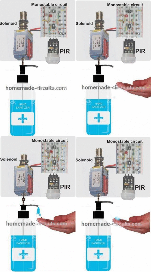
The solenoid pushes the pump shaft of a sanitizer bottle to dispense the liquid in the hands of the user. The concept can be visualized in the following image.
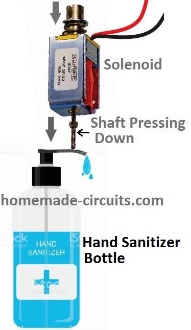
The solenoid in the above image is connected to the output of a monostable circuit.
A monostable circuit is a configuration which causes a momentary high output in response to a momentary input trigger. The output stays high for a predetermined fixed period regardless of the input trigger duration.
In this automatic sanitizer dispenser circuit the monostable is triggered by a PIR as soon as an approaching human hand is detected by the PIR.
The monostable in turn activates the solenoid for some moment of time as determined by its RC timing components.
The activation of the solenoid causes its central spindle to quickly push and pull in the vertical direction, pressing the pump handle of the sanitizer bottle once.
This eventually causes the bottle to dispense the sanitizing liquid into the hand of the user.
Once the user withdraws his hand from the system, the PIR shuts down, and the monostable also deactivates the whole system, until another user brings his hand in the range of the PIR to repeat the procedure.
The monostable triggering circuit for the proposed automatic hand sanitizer dispensing unit can be designed using transistorized monostable or through a popular IC 555 based monostable circuit.
We will discuss both the variants in the following discussions:
Transistorized Hand Sanitizer Dispenser Circuit
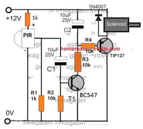
The transistorized version of the circuit looks very straightforward. When the PIR device detects a human intervention, it conducts and sends a pulse to the base of T1 via C1.
The current through C1 instantly activates T1, which in turn activates T2 and also the solenoid pump.
In the meantime, C1 quickly charges and prevents the entry of any further current to the base of T1, thus blocking the repeat DC pulses from the PIR output. This ensures that the system works only momentarily for each detection, and then shuts down until the hand is removed and a fresh cycle is initiated.
This one-shot activation of T1/T2 ensures that the connected solenoid load activates to generate a single push-pull action on its magnetic spindle.
The spindle operates the sanitizer pump handle to dispense a single dose of the sanitizing liquid on the user's hand.
You can notice that the solenoid is connected at the emitter side of the transistor, instead of the regular collector side. The emitter connection actually ensures that the solenoid activates with a gentle soft-start pushing in response to the charging of the 10uF capacitor C2.
If it is connected at the collector side would result in the solenoid being pushed with a sudden thrust, which might not look very impressive.
Simplifying the above Design
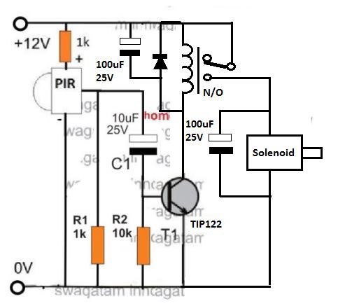
The above transistorized contacless hand sanitizer could be further simplified by using a relay as shown in the following design:
Using IC 555
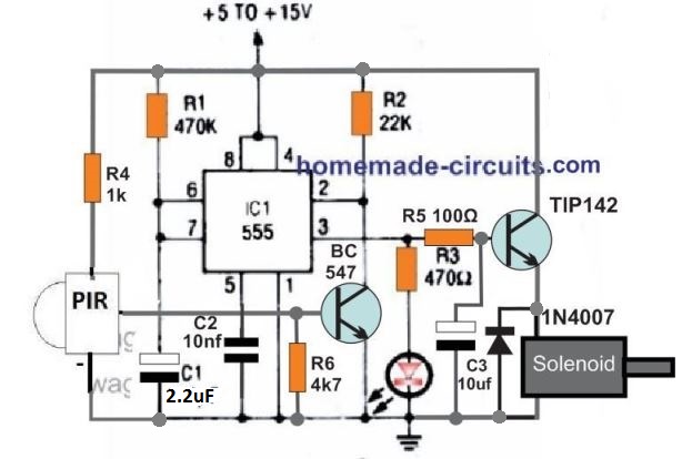
The figure above shows a standard IC 555 monostable circuit. Here, when pin2 is grounded, causes the output pin3 to go high for a period decided by the R1, C1 values or their product.
In this automatic sanitizer dispenser design the R1, C1 is calculated to produce an approximately 1 second output high, in response to a low signal at pin2.
When the PIR detects a human hand, it conducts and switches ON the BC547 transistor which in turn triggers the pin2 of the IC.
This instantly causes the pin3 to go high and activates the TIP142 transistor and the connected solenoid, generating a 1 second long push and then a shut down pull-up on the solenoid shaft.The pull is generated by the attached spring tension on the solenoid shaft.
Again, in this version also the solenoid can be seen connected at the emitter side of the transistor in order to enable a soft thrust on the solenoid shaft depending on the charging response of C3.
An animated view of the whole system can be visualized in the following GIF image.
Infrared Reflective Sensor TCRT5000
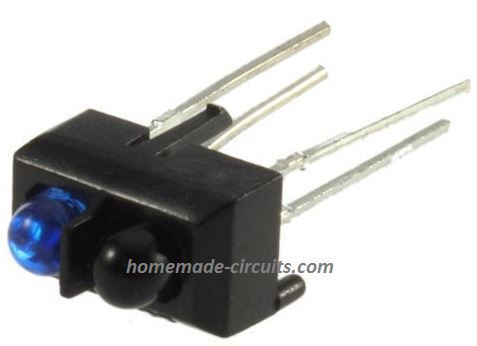
Since PIR is a relatively expensive sensor, a cheaper alternative for making an automatic hand sanitizer could be by using the IR reflective sensor TCRT5000.
The sensor is a simple combination of an IR photodiode transmitter and IR photo receiver packed side by side, inside a single package as shown below:
The characteristics of this proximity IR sensor module can be understood from the following data:
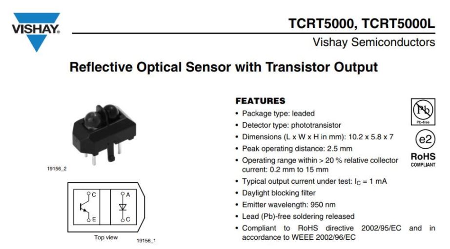
From the internal layout diagram of the sensor we can clearly see that the module consist of a photodiode which emits the IR signal towards the target, and an adjoining phototransistor receiver which is positioned to receive the reflected IR signal from the target.
To adapt the sensor in an automatic hand sanitizer machine, we can yet again implement our work horse IC 555 based monostable, a shown below:
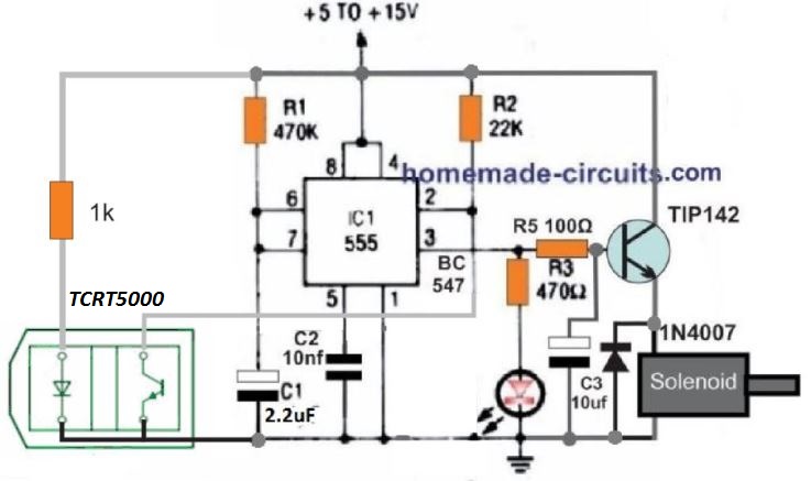
The circuit is quite self explanatory, but if you have problems understanding the details, you can always feel free to use the comment box below for initiating a discussion.
Using HC-SR04 and IC555
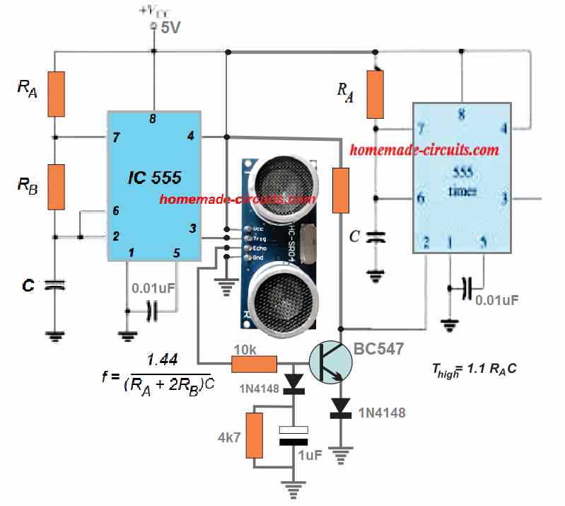
The circuit shown above can be used for implementing an automatic sanitizer dispenser through the ultrasonic proximity detector module, HC-SR04, and a couple of IC 555 circuits.
The left side IC 555 is configured as an astable multivibrator while the right side IC 555 circuit is wired as a monostable multivibtator.
The astable RA, RB, C components values must be calculated to enable a 10us ON and 60us OFF PWM from pin3 of this IC.
The RA and C timing components of the monostable must be adjusted to produce a 1 second high one-shot output from pin3 of this stage.
This output could be used for powering the dispensing pump, motor, solenoid etc as per the requirement of the design.



Questions & Answers
Hello Sir. I’m designing an automatic hand washing dispenser with detergent, water and drier. I’ve used three IR sensor modules on three op-amps of the LM324. My concern is this: Is there a way I can use only one sensor and a timer, such that the detergent, water and drier will work at different times hence allowing a user soap, wash and dry their hands? I’ve sent you the circuit diagram.
Hello Jedidiah,
How do you want the 3 items to operate at different times with a single sensor? Please explain the working, I will try to help.
I will do the necessary changes in your circuit diagram accordingly…
Thank you Sir.
So the arrangement is: Soap 》Water 》Drier. When one arrives at the soap nozzle, the soap is automatically dispensed and after a predetermined time the water is also automatically dispensed and the user washes and rinses their hands and after that the drier come ON to dry the hand. So the user should operate on time.
Jedidiah,
that’s possible.
We can use a 4017/555 based circuit for the sequential operation of the 3 items, by configuring it with the following circuit. The solenoid can be removed in the following circuit:
https://www.homemade-circuits.com/wp-content/uploads/2020/05/hand-sanitizer-using-TCRT5000.jpg
Alright Sir. Thank youso much
You are most welcome Jedidiah, let me know if you have any issues with the concept.
Hello, I want to repair a liquid soap dispenser that uses 3 alkaline batteries of 1.5V. Do you have a diagram of the first (transistorized) circuit for those 4.5V or preferably 3.7V?
Hi, you can use the first transistorized PIR based dispenser circuit with a 4.5V or a 3.7V cell also. Nothing will need to be changed except the 1k resistor at the PIR positive, which might need to be reduced a little, maybe to 330 ohms or so.
Ing. Many thanks for the help you give, it is a unique page. You always answer and give the best solution.
I need the following:
1. a simple transistorized circuit or with 555.
2. Function: to use the bathroom when the person enters, it is activated while they are in the bathroom, then when leaving it is deactivated… turning off the light.
3. I have a broken PIR, I could use its sensor, could you send me the modifications.
Thank you Felix, I am always glad to help!
You can try the 2) concept from this article:
https://www.homemade-circuits.com/pir-motion-activated-relay-circuit/
You can replace the relay contacts with 220V AC mains and a series 220V LED bulb for the lamp.
Hi, your website is very good. How can I modify the 555/tcrt5000 circuit so that after activating the circuit for 30 seconds it does not activate again? the activation would only be possible after the reset. Thank you!!!!
Hi, activation for 30 seconds?, Do you mean solenoid should be ON for 30 seconds?
Exactly, when the tcrt5000 activates the 555, the solenoid is activated for 30 seconds. This can probably be done by changing the value of some resistor. But the most important thing is that after 30 seconds the circuit does not reset automatically but stops working until it is manually reset, turning off and on again. Thank you so much.
That can be probably done by connecting an SCR parallel to the LED of the TCRT5000, and the gate of the SCR connected to the emitter of TIP142 through a series diode and resistor. As soon as the TIP142 conducts it will switch ON the SCR. The SCR will latch and keep the sensor disabled, until the SCR is reset again.
The 30 second delay can be adjusted by increasing the value of c1 appropriately.
Thank you so much!!!!
Trying to simulate a circuit in NI MultiSim. I am currently unable to find a proximity sensor for my circuit simulation. Any help will be deeply appreciated.
Can’t suggest much, since I have never used simulators for my experiments!
Thank you very much for your help and advice really appreciate it.
You are welcome!
Just want ti find out. I want to connect 4 × 18650 lithium battries. They rated 3.6v each so 4 will give me 14.4v. See in your diagram you showed 5v connected to pin 8. Can i connect 14.4 to pin 8? Then the diagram on the right see you show RA is that a kind of resistor? And where you show C is it a potentiometer? And last of all the grounds can they all be connected to same place?
Thanks
The ultrasonic module requires 5V supply according to me, so if you use 14V for the 555s, the UC module will need a 5V regulator, and the trigger input will also need to be protected with a 1K series resistor and a 5 V zener across ground.
All the orange rectangles are resistor…C are capacitors.
All grounds should be connected in common.
So what would be better to use then? Arduino pro mini or 555 timer? Is there a big diffrence on battery consumption between the two?
Arduino is the right way to go! Battery consumption will be more for the arduino, but it is the accuracy of the result that really matters
How do you connect 555 timer with hc-sr04 ultrasonic sensor with 3-6v brushless pump with NO Arduino? For automatic hand sanitizer. Diagrams will be appreciated
Thanks Gary
You can do it with the following following steps:
Create a 555 based astable with a 10us ON time and 60ms off time output PWM. This pulse is applied to the trigger of the HC-SR04.
Configure the ECHO pin of the HC-SR04 with a transistorized monostable which requires at least 0.5 second duration pulse from the ECHO pin to switch ON the solenoid for around 0.5 second.
Thank you for the reply you dont perhaps have a diagram? Im still very new to all of the electronic stuff so need to see a diagram so i have an idea what you talking about.
At the moment im using hc-sr04 ultrasonic sensor with 3-6v brushless pump on Arduino uno R3. Want to swap out the Arduino uno R3 it uses far to much power on battries. Want to put a 555 timer in instead of uno. How would i do that plus diagram
Thanks
No problem, I have added the circuit diagram at the end of the above article.
can i get circuit using ultra sonic sesor HC SR 04 , using 555 ic,
sensing-pump on-delay 2 sec-pump off(inspite of sensor on or off).
with regards
Brijesh
I will try to publish it soon and let you know.
Thanks for sharing this. But these doesnt work in outdoor, am i correct, i mean under sunlight,
can you make one with works in outdoor by using sensors like TSOP, ultrsonic sensor etc…..
You can use the LM567 versions explained in the following article, for making the the system immune to sunlight
https://www.homemade-circuits.com/simple-proximity-sensor-circuit/
Thank you. Let me try
Hi sir,
Instead of PIR sensor , can i connect TSOP1738 sensor on 3rd circuit. If yes mean what modification i have to do on 3rd circuit.
Because PIR based ciruit is not working properly in outdoor area
Kindly advice
Hi Prasanth, it is possible but TSOP1738 can be too sensitive and has a long range of detection, so it can detect the surface even a meter away and keep circuit ON all the time.
You can use photodiodes instead….
Hi sir,
I’m going to build 3rd circuit, my doubt is as per your 3rd drawing can i give direct 12v with 1k resistor to TRCT5000 sensor or i have to include any voltage regulator between the main power to resistor to sensor. Kindly advise.
Hi Prasanth, In the last diagram or the 4rth diagram, no regulator is required for the opto, the 1k resistor will not allow the current (If) to exceed 60 mA through the LED of the opto coupler at 12 V, so the LED will be safe.
Hi sir, I’m an Mechanical engineer and im new to this electronics field. I’m having one doubt on 3rd circuit. I’m going to use 12v power to powerup the 3rd circuit .my doubt is How many watts resistor i have to select.
Hi Prasanth, in the 3rd circuit all the resistors are 1/4 watt rated
Hi sir , thanks for your valauvable reply. In last circuit (4th circuit drawing) also we can go ahead with 1/4 watts resistor!!! Am i right sir.
Hi Prasanth, yes all the circuits shown above can work with 1/4 watt resistors
Hi sir,
Question on Circuit no 3 – BC547 transistor is not required for 3rd Circuit? Can you please explain to get better understanding on 3rd circuit.
Prasanth, the TIP122 should be actually a BC547, the diagram is wrongly showing the relay driver transistor as TIP122, please correct it in your circuit
Hi sir , your article is very use full to us to get more knowledge on electronic circuits.
I’m having 2doubts in above circuit.
1. In your 3rd circuit , we have to use TRCT5000 sensor or TRCT5000 Sensor module.
2.can i use normally closed solinoid valve (RO water solinoid device) for the above circuit.
Dear sir,
Thanks for your valuable reply. I’m planning to go with 12v dc power for 3rd circuit , my doubt is how many amps required to drive the solinoid valve for 3rd circuit. Kindly suggest the suitable dc power adapter specification. This helps me to do this project.
Hello Prashant, the current will depend on the solenoid rating that you want to use. The adapter current will be according to the solenoid rating.
Hi Prasanth, I have provided all the details in the diagram, and the adjoining datasheet of the sensor. You have to use exactly as suggested in those diagrams.
You can use type of solenoid, and adjust the shaft accordingly with the sanitizer bottle mechanism