In this post we investigate a circuit, designed for implementing an automatic sliding gate or door action, and includes a set of features as specified in the request. The idea was suggested by Mr. Andreas.
Technical Specifications
Can you help me to design a simple sliding gate controller. How can work its like this...Press a switch and open the gate, after a minute the gate close again.
If during the closing someone passing in front of the gate then the gate opens again(with the help of infrared cell??).
Reaching at the end(Stopping) during opening and closing its made by magnetic or limit switch.. Note this system must work on 24V.
Many thanks,
Andreas Christodolou
The Design
The proposed automatic sliding gate controller circuit may be understood as explained in the following points:
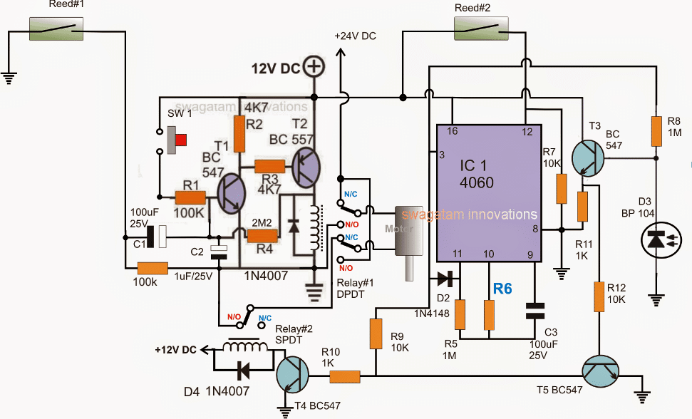
Referring to the circuit below, it can be divided into three stages: the set-reset latch using T1/T2, the monostable timer using IC 4060 and the IR interceptor using T3/T5.
Note:
- Please disconnect the 100k below C1 from the ground, and connect it on C1 positive terminal, meaning the 100k should be connected right across C1 terminals and nowhere else.
- R6 needs to be calculated for getting a 1 minute delay before the gate initiates a reverse closing motion
Let's assume the gate to be in the "closed" position with Reed#2 actuated by the relevant gate magnet.
This ensures pin#12 of the IC 4060 to be rendered high and the IC stays inactive (pin#3 switched OFF).
In the above scenario, the relay#1 is already OFF, with its N/C position closed (because T1/T2 are OFF), and T4 is also OFF due to the absence of a base drive, which implies relay#2 is OFF and in the N/C position.
With relay#2 in N/C, the motor is switched off due to the absence of a positive link via the relay#2 N/O contact.
The entire circuit is thus in a switched OFF condition.
Now, as requested, the opening of the gate is initiated by pressing SW1 momentarily.
Pressing SW1 instantly latches T1/T2 via R4, toggling relay#1 such that its N/O contacts close, which in turn forces the motor to slide the gate towards the "open" direction.
As soon the gate slides away from its "close" position, reed#2 is released, which instantly enables the IC 4060 and it starts counting, with its pin#3 now with a logic zero.
The gate rolls on until it reaches the extreme end when the other relevant magnet fixed on the gate activates reed#1.
On activation, reed#1 pulls the base of T1 to ground via C1, breaking the latch, which in turn deactivates relay#1 and its contacts return to their N/C points.
However relay#2 still being in a switched OFF condition causes the motor to halt due to the absence of power through relay#2 (N/O) points.
In the meantime, IC 4060 completes its counting allowing a high to appear at its pin#3. (the IC now latches in this position via D2)
This immediately activates relay#2, enabling a reverse activation of the motor.
The motor starts sliding the gate towards the "close "position, and the moment it reaches the "close" end, reed#2 is activated yet again. At this position, the IC is again reset causing a no signal at its pin#3, deactivating relay#2 and....shutting off the motor. The circuit reverts to its original standby state.
Calculating the Time Delay
The universal equation for finding the timing component Rt and Ct values is:
f(osc) = 1 / 2.3 x Rt x Ct
2.3 is just a constant with regards to the ICs internal configuration.
Preventing Accidental Entry
As per the request, the circuit needs to respond to an accidental entry of an individual through the gate in the course of its closing process, in order to safeguard the individual and also the gate mechanism.
This is implemented using an infrared transmitter receiver assembly, as shown in the diagram.
D3 is a receiver IR photodiode which is kept switched ON through a perpendicular IR activated transmitter beam, focused on D3, the beam position is supposed to be in a straight line along the gate's sliding action.
As long as D3 stays actuated, T3/T5 are unable to conduct, however in the presence of an individual who may be trying to make a quick entry across the gate while its closing, would in the course obstruct the IR beam, triggering T3/T5 which in turn would conduct and disable T4, and relay#2.
With relay#2 disabled, the door would instantly stop its closing motion and halt on the spot until the individual has completely crossed the restricted line of action.
For the sake of simplicity, a momentary halting of the gate looks more appropriate, instead of enforcing a reverse opening action which might unnecessarily delay the process.
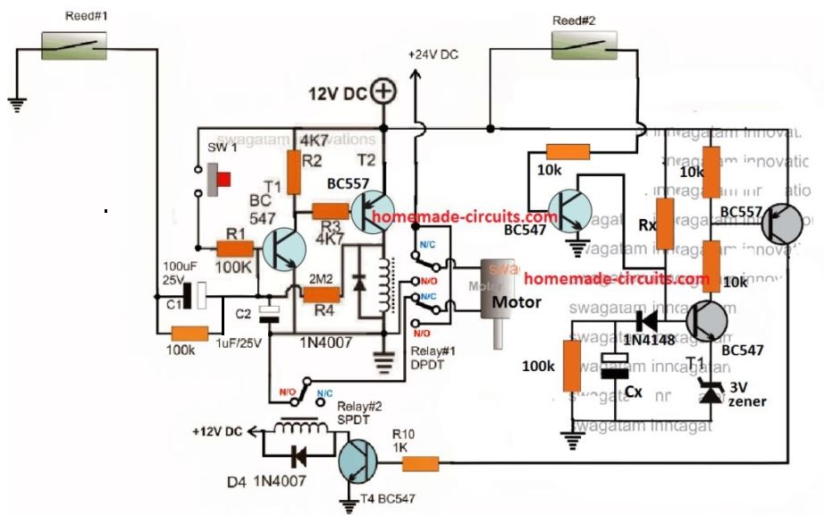
Using a Transistorized Timer Stage
The above could be much simplified by replacing the IC 4060 timer stage with transistorized delay ON timer, and by removing the IR detector stage. The complete circuit diagram could be witnessed below:
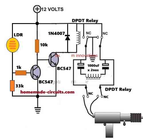
The IR Transmitter Stage
The IR transmitter which is supposed to focus a beam on D3 may be built using the following circuit:


Comments
HELLO SWAGATAM, im a 2nd year college student, I have a project that is the making a sliding door that uses only 9 volt, I also have a servo motor if this can help
Hello Radg, can you please provide the complete operational specifications of your requirement…I will try to help!
Hi SWAGATAM, this is a similar problem to one I am trying to solve. However I am using Wifi enabled home automation. In addition I have an existing gate controller with safety IR reverse.
The challenge I have is that the gate controller has two separate inputs for externally controlled open and close control. The open control or the close control are actuated with a momentary closed circuit. However the WiFi remote unit I have only has one set of contacts. It expects the controller to handle press once for open…. press again for close…. It would seem to me to be solved by a simple flip flop design. But my electronics experience is a little scratchy since it is >30 years ago. Do you have a recommended design to break this single momentary contact into two separate contacts with alternating action? and if possible have the timing of the momentary closure of the single contact be exactly reflected by each of the alternating dual contacts. i.e. if I set the momentary contact timing for the single contact to 1 sec via the WiFi control app, I would like each of the alternating contacts to be closed for 1 sec. Likewise if I alter the timing on the app to 2 secs, I would want the alternating contacts to be at 2 secs each.
Hi Rob,
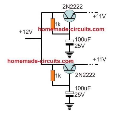
The following circuit should do the job for you. The timing can be adjusted by adjusting the values of the 10uF and 2.2K parts, however the timing cannot be synchronized with your WiFi timing… it will need to be done externally and manually. Additionally you can add a 1K across the junction of 10uF/2.2K and ground for better timing control.
https://www.homemade-circuits.com/wp-content/uploads/2022/12/flip-flop-trigger.jpg
I should have mentioned this is powered by USB 5V supply.
Thanks so much in advance.
Rob
hello very interesting circuit could some improvements be made?
1 when it stops from the infrared stop to turn back;
2 to be done with 220V AC?
3 or r6 to be a trimmer?
thanks
Hi, Thank you!
The first one can be difficult to add since it could make the circuit more complex.
2) is possible if the circuit is powered from a 12V AC to DC adapter
3) R6 can be a trimmer with a 1K resistor.
Good day Sir.
I am a first year engineering student and I need to make a similar circuit as the one discussed in the article(automatic gate, should close after 10 seconds and should stop automatically if a person steps in front of the motor gate whilst it is closing) however it needs to be controlled by a push-button and the circuit should be done on Simulink. It should be a simple circuit and microcontrollers are not allowed. Please may you assist urgently? Thanks so much
Hello, sorry designing the circuit using simulink may not be possible!
Ok thanks. What type of software did you use to design this circuit ?
I don’t use any software, I use my knowledge and mind simulation.
Good day,Swagatan .
In the above circuit description, you kept on mentioning Reed #2 without mentioning reed#1 please when is Reed 1&2 deactivated, actuated or released?
Thanks for all your efforts.
Thank you for pointing out the mistake, I have corrected the relevant sentences in which reed#1 was wrongly mentioned as reed#2.
Hi,
Thanks again for the circuit. I have solved the problems I was having with the circuits. A 0.22uf cap across pin12 of IC4060 and the positive rail fixed the issue.
I have two of these circuits to open a pair of gates that will run off a 12 volt battery. While they work fine when attached separately to the battery, they have issues when they share the same power supply.
Is there a way of creating two independent supplies from a 12 Volt battery.
Thanks for your help.
Cheers
Hi, that sounds great! Glad you could solve it simply with a capacitor. You can probably try isolating the common positive as shown in this diagram.
use this only for the IC 4060
here’s a more effective way of implementing the same:
Hello and thank you for designing this circuit.
I have made the circuit but removed the section relating to T3 and T5 as I did not wish to have a sensor present.
I am having a problem with the circuit though, and am seeking your advice.
The circuit works fine to open the gate. When, though, the counter reaches the time to close the gate, it triggers the relay but only momentarily and then restarts counting. If I remove the connections that control the earth to the motor, it works as it should. As soon as I reconnect the earth to the motor and pass current through the relay terminals it does not work properly.
The relay is capable of switching up to 5A and the motor is drawing about 2A.
Can you please offer a suggestion as to what is wrong? I would like to make it work and have spent many hours on the project.
Thank you in advance for your help.
Cheers,
Gary
Hi, I checked the circuit again and I found nothing wrong in it as far as the operation sequence is concerned. Did you connect the diode D2 correctly? please confirm that it is connected correctly across pin3 and pin 11 with the shown polarity.
Also please connect the 100k below C1 as suggested under the diagram.
Hello again,
Thank you for the quick reply.
I’ve checked and rechecked solder joints and components etc. I have used pin 15 not pin 3 for the timing sequence as I did not believe it would impact the circuit. Am I wrong? The resistors and cap I have used give a 40 second pulse at pin 15.
The circuit works properly if there is nothing connected to the poles of Relay#2. At the programmed time relay#2 latches and counting stops until the circuit is reset. As soon as the relay switches with the motor connecting to earth and current passes through the poles, there appears to be a pulse through the circuit and IC#1 resets and begins counting again. This cycle will continue for 5 to 10 minutes then the relay will latch and the motor runs to the gate closed position.
If I then press S#1 to open the gate, the motor will run to until Reed#1 closes. The motor stops and then at the appropriate time the relay will try to latch and close. Sadly the problem appears again and the multiple cycles of R#2 latching and immediately unlatching begins until at some time later it eventually latches and the motor runs.
To minimise pulses through the circuit, I have put a 0.1uF bypass capacitor on pin16 of IC#1 but that made no difference.
It is very confusing.
I had the gates working with the simple gate opening circuit you published, but as I wanted them to close automatically I decided to use this circuit. If I cannot make this circuit work, is there a way to use a timer to replace S#2 on that circuit?
Thanks again for the reply and your help.
Cheers,
Gary
Hi, if it is happening due to motor spike then you can first try conforming this by operating the IC 4060 from a separate power supply. Just isolate pin16 of the IC and the positive side of reed#2 and connect them to an external +12V, make sure to connect the ground line of this power supply with the negative of the motor circuit. If this works then we can go ahead and try adding stabilizing agents like diode, resistor and capacitor across the IC supply pins until the problem is solved…
Hi,
I found a web site and noted the placement of a capacitor close to pin#12 if the IC. I also noted that they recommend a relay with an internal resistance of at least 280ohms (which mine were not).
So I placed a 220nf cap in the circuit as they described and put an additional 200 ohms across the relay contacts.
So far it is stable on the bench so we’ll see how it progresses.
With respect to a transistor based timer circuit, if you could email or post it online just as a backup that would be greatly appreciated.
Thank you again for your patience and all the best.
Cheers
Hi, I have updated the transistorized version in the above article, you can check it out….
Hi, yes pin12 being the reset pin can be vulnerable to auto resetting due to a spike. The relay coil voltage is related to the contact current rating. Relays designed to switch heavy current load will need to have heavier coil specs and therefore lower resistance. This cannot be a fixed standard value, so suggesting a 280 ohms is incorrect, however the driver transistor must be appropriately rated depending on the relay coil, otherwise the transistor may burn, due to high coil current.
I’ll try to update the transistorized design soon…
Hi and sorry this is becoming a saga,
I did as you suggested but with no luck, the relay kept resetting itself. I disconnected the relay and wired up another one but left it free and not mounted on the board. This relay acted the same, interestingly though if I disconnected the motor earth from the relay it behaved properly but if I touched the relay it triggered a reset, so the static in my fingers was enough to disturb the circuit.
Does this shed more light on the problem.
Cheers,
Gary
Hi again and thank you for your patience,
Agreed, if I cannot make the circuit work with the motor connected then it is useless.
I’ll try to hook up the motor as you’ve suggested with a diode and cap across the power supply and see what happens.
If I have Relay#2 send power to a third relay that is connected to the motor, the circuit works fine. Obviously the spike of the contacts closing is triggering something when the motor is connected to Relay#2.
Very strange but if I can only make it work this way then that is the best solution.
Cheers
Hi, no problem, if still the spike problem does not solve then I will replace the IC section with a transistorized timer circuit, which should be free from these issues.
Hi,
Checked everything and all works fine without the earth to the motor connected.
Timer is operating correctly and all pins on the 4060 are pulsing as it counts.
Interestingly though, the voltage on Pin #15 of the 4060 (the output I’m using) shows 12 volts when it latches but on the base of T4 it is only 0.8 Volts. Should it be this low or should it show 12V?
Apart from that it all looks fine until the relay switches the motor on.
Cheers
Hi, If you remove the earth connections from the relay contacts then how will the motor move? Please clarify this point. Alternatively you can try connecting the all the ground connections from the re;ay directly with the main ground of the power supply through separate thick wires. And also connect a reverse diode and a capacitor right across the motor terminals, and see if that helps!
You can refer to the following diagram for the motor diode and capacitor connections:
https://www.homemade-circuits.com/wp-content/uploads/2012/05/pwm-motor.jpg
Hi, IC 4060 is a highly reliable IC and the spike problem cannot affect it if it is operated from a separate power supply. Please check the timer response separately without the motor circuit isolating pin12 from the reed2 positive. Doing this must switch ON the pin3 of the IC high after a predetermined time, and this situation should get latched permanently until pin12 is touched with a positive potential again. You can connect an LED with 1k resistor across pin3 and ground to verify this. Further you may change the C3 value to check changes in the output time intervals…..C3 should be non-polar.
Also please put an LED in series with T4 base to know how the timer output is triggering T4. Make R9 1K so that the LED lights up brightly
Disconnecting motor earth will not allow the motor to reverse, so that isn’t an option.
Hi Swagatam,
I would like to design a control circuit for a louver system at home. This auto gate circuit could do the job with some changes.
I would like to use one switch to open the louvers from the closed position but would like to be able to stop louvers at any point between the limit switches, so press open button once to open and press again to stop if the open button is pressed again it would just continue to the max open limit switch same for the close button, press it once and the louvers start to close press again and it stops, I am surer you understand what I mean. the motor that I would like to use is a 12vdc motor with a current draw of about 10Amps. I hope you can help me with this project.
Hi Swag,
Thank you very much for the reply, I will have a look at the circuit to see if it would do the job.
I will let you know if I could figure it out or not but will definitely reply with more information regarding this project.
No problem!
Hi Paul,
you can use the concepts explained in the following article:
https://www.homemade-circuits.com/simple-touch-sensor-switch-circuit/
the relay is not erquired, so it can be eliminated. Connect the collector of the BC547 with the base of the T4 of the gate controller circuit.
I have updated the new link, you can check it out now….
ok sir, thank you for your hasty response!
Mario,
You can try the following basic design
https://www.homemade-circuits.com/wp-content/uploads/2018/05/remote-gate-control.jpg
The remote relay can be attached parallel with the push button for enabling remote controlled operations.
The circuit does not include limit switches, and may require modifications across the output pinout configuration for implementing this.
sorry, the diagram has a mistake I’ll correct it shortly and replace the link with the updated one.
Good day sir if I wanted this circuit to work with a 12v supply and motor, what changes would i have to make to it?
Finally, if i wanted to eliminate the timer and allow only that single push button to open,stop and close the gate just as how a garage door push button operates, how could I this?
Regards
Mario
Hi
good day sir i tried the link given for the garage door control using single push-button, but it doesn’t seem to be working.
Sir,
Can you please provide the design of the components in this circuit.
Ajmal, please click on the diagram, and copy all the part numbers as shown, if you show this part number to the shopkeeper he will be able to understand and provide you all the components as per the specs.
resistors are all 1/4 watt rated
Sir, I meant how you got the value of resistors and capacitors like 100k….Have you designed the value of resistors or just put it up with your experience
I got the values by judging the current and voltage parameters across the different positions, It is possible only once you thoroughly know how each parts functions and their technical specifications…
Sorry Swagatam, there is some mistakes in my previous message. Finally I got this circuit work! The circuit should be taken as there is gate in "close" position as a first state. Minus 12V should be connected to the NO position of Relay #2, but in the circuit it shows as it is in NC position by switch, not by remark(NO=NC). Because of that, I get my motor run always without pushbutton pressed. Correction is that minus 12V should be connected to NO, and NC is not connected (stays free).I hope you will correct the circuit. Kind regards.
Hi Bursach, the negative is connected to N/O of relay#2 and is N/C is free and open, please enlarge the diagram to see the details correctly.
and please remember that you must ensure the correct polarity of the motor wire to the relays initially, so that the motor supply orientation becomes correctly aligned and it moves as per the relay switching specifications.
Sorry Swagatam, I have to notice something in this circuit. I have made this circuit but there is a mistake I think. NO contact of Relay #2, should not to be connected to minus 12V directly as circuit shows. It has to be connected to minus of C2, and C2 should not be connected to minus 12V. In this case as circuit shows, and I made according to it, when I apply 12V plus and minus supply, motor starts immediatelly. Without pushbutton pressed. Please correct me if I am wrong.
nice one
hello vincent, I think if you Google this question online you will be able to find many good answers with diagram….please try it.
hello sir…ANDREAS CHRS/SWAGATUM MAJUMDAR.. i really need your help on how to reverse a single phase ac motor…. i will be gratefully if u can provide to me the necessary circuit diagram.. greatchioce@gmail.com thanks alot
Hi Khalid, please explain your requirement and the operations elaborately…if it is feasible I'll try to help