I have been put forth with this question many times in this blog, how do we add a changeover selector switch for automatically toggling of an inverter when AC mains is present and vice versa.
And also the system must enable automatic switching of the battery charger such that when AC mains is present the inverter battery gets charged and when AC mains fails, the battery gets connected with the inverter for supplying AC to the load.
Circuit Objective
The configuration should be such that everything takes place automatically and the appliances are never switched OFF, just reverted from inverter AC to Mains AC and vice versa during mains power failures and restorations.
So here I am with a couple of simple yet very efficient little relay assembly module which will do all the above functions without letting you know about the implementations, everything is done automatically, silently and with great fluency.
1) Inverter Battery Changeover
Looking at the diagram we can see that the unit requires two relays, however one of them is a DPDT relay while the other one is an ordinary SPDT relay.
The shown position of the relays are in the N/C directions, meaning the relays are not powered, which will obviously be in the absence of the mains AC input.
At this position if we look at the DPDT relay, we find it to be connecting the inverter AC output to the appliances through its N/C contacts.
The lower SPDT relay is also in a deactivated position and is shown to be connecting the battery with the inverter so that the inverter remains operative.
Now let's assume that AC mains is restored, this will instantly power the battery charger which now becomes operative and supplies power to the relay coil.
The relays instantly become active and switch from N/C to N/O, which initiates the following actions:
The battery charger gets connected with the battery and the battery starts charging.
The battery gets cut OFF from the inverter and therefore the inverter becomes inactive and stops functioning.
The connected appliances are instantly diverted from the inverter AC to the mains AC within a split second such that the appliances doesn't even blink, giving an impression that nothing had happened and the are kept operative continuously without any interruptions.
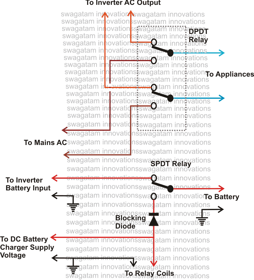
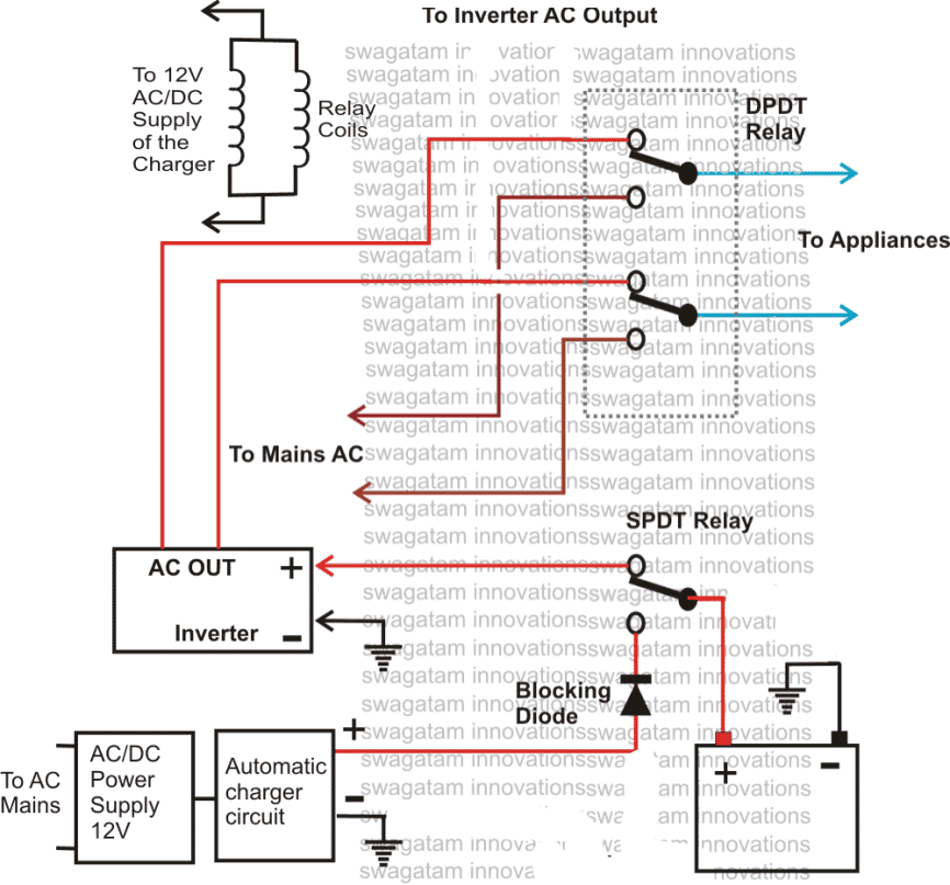
A comprehensive version of the above can be witnessed below:
2) 10KVA Solar-Grid Inverter Changeover Circuit with Low Battery Protection
In the second concept below I have explained how to build a 10kva solar grid inverter changeover circuit which also includes a low battery protection feature. The idea was requested by Mr. Chandan Parashar.
Circuit Objectives and Requirements
- I have a solar panel system with 24 Panels of 24V and 250W connected to generate a output of 192V, 6000W and 24A. It is connected to 10KVA, 180V inverter which delivers the output to drive my appliances during daytime. During night the appliances and inverter run on grid supply.
- I request you to kindly design a circuit which will change the inverter input from grid to solar power once panel start generating the power and should again revert the input from solar to grid once darkness falls and solar power generation falls.
- Kindly design another circuit which will sense the batter.
- I request you to kindly make a circuit which will sense that battery is getting discharged below certain threshold value say 180V (esp during rainy season) and should switch the input from solar to grid even though some amount of solar power is being generated.
Designing the Circuit
The 10kva solar/grid automatic inverter changeover circuit with low battery protection which is requested above can be built using the concept presented in the following figure:
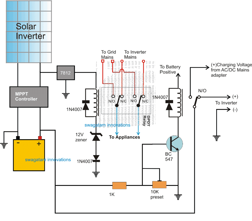
In this design which may be slightly different to the requested one, we can see a battery being charged by a solar panel though an MPPT controller circuit.
The solar MPPT controller charges the battery and also operates a connected inverter through an SPDT relay for facilitating the user with a free electricity supply during day time.
This SPDT relay shown at the extreme right side monitors the over-discharge condition or the low voltage situation of the battery and disconnects the inverter and the load from the battery whenever it reaches the lower threshold.
The low voltage situation could mostly take place during night when there's no solar supply available, and therefore N/C of the SPDT relay is linked with a AC/DC adapter supply source so that in an event of a low battery during night the battery could be charged for the time being through the mains supply.
A DPDT relay can be also witnessed attached with the solar panel, and this relay takes care of the mains supply changeover for the appliances.
During day time when the solar supply is present, the DPDT activates and connects the appliances with the inverter supply, while at night it reverts the supply to grid supply in order to save the battery for a mains failure back up situation.
UPS Relay Changeover Circuit
The next concept makes an attempt to create a simple relay changeover circuit with zero crossing detector which may be used in inverter or UPS changeover applications.
This could be used for switching-over the output from AC mains to inverter mains during inappropriate voltage conditions. The idea was requested by Mr. Deepak.
Technical Specifications
I am looking for circuit comprising of the comparator (LM 324) to drive a relay. The objective of this circuit is to:
1. Sense AC supply and switch relay 'ON' when voltage is in between 180-250V.
2. Relay should turned 'ON' after 5 seconds
3. Relay should turned 'ON' after zero voltage detection of supplied AC (Zero voltage detector). This is to minimize arching in the relay contacts.
4. Finally and most importantly, the relay switchover time should be less than 5 ms as a normal off-line UPS does.
5. LED indicator to indicate the state of relay.
The above functionality can be found in UPS circuit which is bit complex to understanding since UPS has many other functional circuit beside this. So am looking for a separate simpler circuit which only works as mentioned above. Kindly help me to build the circuit.
Component available and other details:
AC mains = 220V
Battery = 12 V
Comparator = LM 324 or something similar
Transistor = BC 548 or BC 547
All type of Zener are available
All types of resistor are available
Thanks and Best regards,
Deepak
The Design
Referring to the simple UPS relay changeover circuit, the functioning of the various stages may be understood as follows:
T1 forms the sole zero detector component and triggers only when the AC mains half cycles are near to crossover points that's either below 0.6V or above -0.6V.
The AC half cycles are basically extracted from the bridge output and applied to the base of T1.
A1 and A2 are arranged as comparators for detecting the lower mains voltage threshold and the higher mains threshold respectively.
Under normal voltage conditions the outputs of A1 and A2 produce a low logic keeping T2 switched Off and T3 switched ON. This allows the relay to remain switched ON powering the connected appliances through mains voltage.
P1 is set such that voltage at the inverting input of A1 becomes just lower that the non-inverting input set by R2/R3, in case the mains voltage falls below the specified 180V.
When this happens, the output of A1 reverts from low to high triggering the relay driver stage and switching off the relay for the intended changeover from mains to inverter mode.
However this becomes possible only when the R2/R3 network receives the required positive potential from T1 which in turn takes place only during the zero crossings of the AC signals.
R4 makes sure that A1 does not stutter at the threshold point when the mains voltage goes below 180V or the set mark.
A2 is identically configured as A1, but it's positioned for detecting the higher cut-of limit of the mains voltage which is 250V.
Again the relay switch over implementation is executed only during the zero crossings of the mains AC with the help of T1.
Here R8 does the momentary latching job for ensuring a smooth transition of the switching.
C2 and C3 provides the required time lag before T2 can conduct fully and switch ON the relay. The values may be appropriately selected for achieving the desired delay lengths.
Circuit Diagram
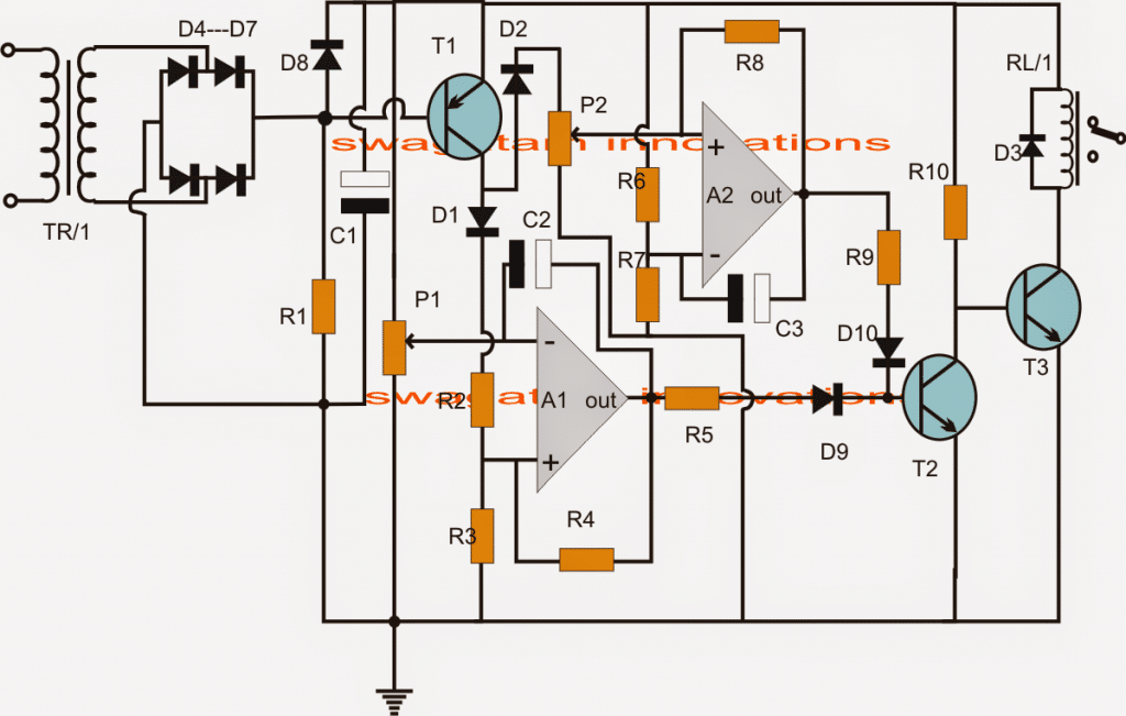
Parts list for the zero crossing UPS relay changeover circuit
- R1 = 1k
- R2,R3,R4,R6,R7,R8 = 100K
- P1,P2 = 10K PRESET
- R5, R9 = 10K
- D3,D4---D10 = 1N4007
- C1,C2 = 1000uF/25V
- T1 = BC557
- T2 =BC547
- Z1= 3V ZENER
- A1/A2 = 1/2 IC LM324
- RL/1 = 12V, SPSDT RELAY
- TR/1 = 0-12V STEP DOWN TRASFORMER



Questions & Answers
1)Inverter AC is the AC generated by the inverter.
2)appliance refers to the household load
3)Inverter battery input refers to the supply points of the inverter (+) and (-)
4)"To battery" means to battery which is being used for operating the inverter.
5)DPDT and SPDT both relays will have it's own separate coils, connect them together in parallel to the points indicated as "to relay coils"
yes that's correct.
The relay coils are not connected with the battery, it's connected with the AC/DC charger output.
so as long as AC mains is present the charger will keep the relays energized.
Here the charger should a separate DC unit and the over charge relay must be wired with the battery positive, this will enable the over charge feature to activate separately only for the battery, other solutions can also be figured out, there's plenty of options open.
I have already comprehensively explained it in the above article, you can use the above explained design for your application, it's exactly as per your needs.
hello sir,
i think i may have found a solution to this slight problem i told you about last year.
The problem was that since the battery charger supplies power to both relay coils and being that the battery charger is an automatic one this means that once the voltage is cut off because the battery has been fully charged it will automatically switch off the relays forcing them to switch back to inverter even with AC mains present.
The simple solution would be that both relays are powered from a separate divider/bridge rectifier network which the appropriate voltage so that even when the battery charger cuts off voltage to the battery both relays will still be powered on and this means that the battery still remains cut off from the inverter and the appliances are still powered from AC mains.
micheal
Thanks Michael,
But it's been already solved above as shown in the second diagram.
We can see that it's done by powering the relay coils directly from the AC/DC main power supply while the battery is being charged through a separate cut off stage.
Sir me bhanu how can i send a E-mail to you.
I have a simple mobile charging circuit I have already assembled this circuit but i am not getting the desired output so I need help from u………….plz sir give me a e mail id…Thank you
bhanu, you can send it to hitman2008(at)live.in
Dear sir! The DPDT relay coil is energized by AC or DC.
Dear Yasir,
all relay coils are connected with the AC/DC adapter power supply output, meaning with a DC acquired from mains AC.
hi bro.any harm to operate a relay with higher voltage than its rating?? i mean can i give a 13.7 v to a 12 v relay??
hi bro, a couple of volts higher won't harm the relay .. but would dissipate and waste a few tens of milliamps
good day sir, i want make a pure or modified sine wave inverter of exactly 1.2Kva that will have battery charging section with couple of only SPST relays to make it fully automatic as described in this post, please i want you to fully guide me on this. thanks
pls i am sorry for the mistake in the earlier post i want to use only SPDT relays not SPST be
Hi Muhammed you can try the following design:
https://www.homemade-circuits.com/2012/02/how-to-make-mini-homemade.html
Sir, the relay coil of the DPDT is shown clearly connected to the 12V DC charger, where is the relay coil of the SPDT connected?
The DPDT and the SPDT have singles coils…both are shown connected to the charger supply.
sir, can i use solar panel instead of AC main supply to charge the battery? another thing is that i want to use a 10W light as load for this project so can i use a 6V 4.5AH battery?
Dipto, yes that's possible, you can go ahead as per your mentioned plans.
Thank you sir for your reply.
I have another question is it possible to make a triple changeover? For example if one battery is empty then another battery would give backup by switching automatically. I am interested to add solar & hydro generator with the main supply for my project.
Dipto, it is possible to get a split battery changeover actions, you can refer to the following articles for more info:
https://www.homemade-circuits.com/2014/05/twin-or-split-battery-charger-circuit.html
https://www.homemade-circuits.com/2013/08/automatic-dual-battery-charger-with.html
Thank you sir for your reply. The 'split battery charger circuit' you mentioned is exactly what I required. I'll be using solar and hydro to charge the battery 1 & battery 2 respectively, hopefully it turns out well. I will inform you about the outcome.
Sir I have bought DPDT relay from the shop however it has two COM (common) pins what should I do with those pins? The relay has total of 8 pins.
please show me its pic I'll help you to identify the pins
The relay looks like this (the link given below).
https://drive.google.com/file/d/0ByOP1BiJWDUaWk51dDJReUtPUEE/view?usp=sharing
OK, the common terminals are the poles of the relay shown as black contacts in the above diagram, the N/C are the upper white circles, while the N/O are the lower white circles in the relay contact diagram
Hello Sir, can you tell me which software did you use to make this circuit diagram? I want to use it for my project.
Hello Dipto, I did not use any software, I designed it myself.
What I meant was which software did you use to draw them?
CorelDraw
pls i have not been able to connect my 3pole contactor? how do i make the connections cox the contactor has L1, L2, L3 in one side and at the other has T
1L1 3L2 5L3
2T1 4T2 6T3
then it has also
13 NO 21 NC A1
14 NO 22 NC A2
pls how can i make the connections on this because my main power grid is single phase and my generator also is single phase. how can i use it so as to b a changeover?
please use schematic and circuit diagram and symbol to illustrate and explain please
I am sorry I don't have much idea about the contactor's operational details so won't be able to explain the connections
Hi Swagatam,
Cool came across so many changeover ckts … This one is very interesting. I have one question though.
Can i use SPDT replacing the DPDT one? by connecting the nuteral lines of alternator and main together and only connecting the phase line to SPDT relay and toggling it. Here again, can i use 7 amps relay for switching AC mains? If not what is the suggested amps rating of the relay coil?
Thanks Sham, if the generator also has a neutral identical to the mains then you can make them common and use a SPDT switch, however if the generator neutral is not a permanent neutral and keeps alternating from live to neutral then SPDT will not do.
7 amp relay contacts will do, if the max wattage of the load is not above 1000 watts
Hi Swagatam,
Thats good. So i dont have to spend on DPDT since i have lot of SPDT ones. I am not using generator here. Its UPS( using as inverter ) so my neutral will always be constant. Inverter supports Max load of 600W so no issues with inverter. But when running on mains i think it can go beyond 1000W. So i will use 20 amps relay instead.
Will update you once its done. Thanks again.
Hi Sham,
are you your inverter has a constant neutral? confirm it first and then go for the SPDT version, otherwise you might burn the switch or the inverter fuse..
Yes Swagatam, output of UPS will have constant nuetral terminal… Otherwise phase and neutral will toggle in home AC mains
OK, then it's fine to use a SPDT switch…
Hi Swagatm,
I have rigged up the circuit. Its working fine as per my requirement. I have used single SPDT of 20 A for this purpose. Tested for 15 days.Running smoothly. But only thing is it takes a second to switch over and in the mean time lights goes OFF and ON.
Thanks for your suggestions.
Hi Sham,
A relay will never take a "second" to operate, it will operate in milliseconds I think the DC input has a capacitor which might be keeping the relay switched ON even after the mains failure….this capacitor value needs to be reduced….or a transistor driver could be introduced for making the response instant.
Pls sir, is it advisable for me to connect the coils of a 12v 10amp relay to 14v 1amp dc source and connect its two pole to load and it's two no to mains with it's two nc to inverter will it burn the relay(it's a dpdt relay)
why do you think it would burn the relay??…your wiring is correct and as per the shown diagram above so definitely it will work but only as long as the load does not exceed 5 amp or 6 amp max
you can reduce the 14V to 12V by adding 3nos of 1N4007 diodes in series with the relay coil
Swagatam:
I would like to replace the SPDT relay with 2 scr's. Would you consider a circuit to replace that relay?
I believe a relay would need to handle 60 amps to be effective for the inverter side… and a smaller SCR for the Charger side.
Many thanks for the great work you do.
Thanks Musicgirl, the concept looks useful, I'll try to design it soon and will publish it in my site as a new article.
Hello. I only have one question: the SPDT relay disconnects the inverter under load. This creates a big shock on the MOSFETs from the inverter (not to say a possible arc in the relay, depending on the load of the inverter). I cut the DC connection to my inverner under load once (I put a smaller fuse than necessary on the battery wire) and half of the MOSFETs blew up.
Wouldn't be much better if you transfer the load first and later cut the DC power to the inverter ?
you can use freewheeling diodes across the mosfet drain and source to rectify this issue….or to implement your idea you can simply add a high value capacitor across the SPDT relay coil and keep it isolated from the DPDT relay coil through a diode….but the first option looks more logical to me
Hello. I only have one question: the SPDT relay disconnects the inverter under load. This creates a big shock on the MOSFETs from the inverter (not to say a possible arc in the relay, depending on the load of the inverter). I cut the DC connection to my inverner under load once (I put a smaller fuse than necessary on the battery wire) and half of the MOSFETs blew up.
Wouldn't be much better if you transfer the load first and later cut the DC power to the inverter ?
You must use a flywheel diode with relay in order to prevent this. This is caused by the back emf of the relay coil. And diode protects the circuit driving that relay from its back emf. You can use general purpose diode like 1n4007 or 1n4148. Read about Flywheel diode or freewheel diode.
Helo Mr swagatam! I am a fan to your skills. I want to ask; Does this design implies that the same inverter tranfo is used for charging the battery or do I need a separate transformer for that? And if so, can I get a design on how to do this? Thanks a lot sir
Thanks Odion, same trafo cannot is not used here for charging/inverting, the diagram suggests only the changeover section from mains to inverter and vice versa, the charger section utilizes a separate power supply which may be a trafo based or an SMPS based.
Sir please! I need to work with one transformer to minimize costs of production. Any design to work this out? I have done some personal design but they are not promising. I need a charging section that is not done by the inverter mosfets sir but both must use one tranfo
odion, I have explained one such concept below
https://www.homemade-circuits.com/2012/12/single-transformer-inverterchargerchang.html
however inverter mosfet is not used for charging in the above link
Odion, you can also use this design. And you can modify it to have more power.
https://www.homemade-circuits.com/2016/10/transistor-ups-circuit-with-charger.html
Thanks Syed!!
And sir! Can I get a design of smps that can handle current up to 60Amps?…..thanks alot
you can try the following design
https://www.homemade-circuits.com/2014/07/adjustable-0-100v-50-amp-smps-circuit.html
Sir! I am thinking of using the centre-tap and one part of the 12v as ac supply into the separate charging section for charging the batteries during supply from mains. Can I get a design to match this!? I hope to meet you someday
Odion, a couple of links were suggested under your previous comments, please go through those links, they seem to closely match your simulation of a single trafo inverter/charger design
Please for my charging circuit the AC mains Live is through the relay so anytime the the battery is full the relay will open which means there will be no live to power the changeover relays which will make inverter trigger ON in the presence of AC mains. Please can this be solved using multiple trafo with different 12V rectified to the relay coils? If not please help me out..
Congratulations on the new look of your site
thank u so much for the circuit it work for me and you are in deed my hero in electronic please keep the good work going and may Almighty reward you greatly
Please i have one request can u please give me a good filter circuit i want to use it for my sg3524 inverter i build here is my email faithjumbolives@gmail.com
Thanks and best regards
Thanks Faith, I am glad you liked my site’s new look…
I am sorry I do not have a tested filter circuit, but you can easily make one through some trial and error, begin with a single LC first at the output side of the trafo
Hello sir Swagatam,
I want to design an inverter that utilizes the same transfo for charging the batteries through the MOSFETs. The transfo will have a separate winding that produces (14.5-0-14.5V) at the input when mains is applied there. Could you please suggest a changeover switch that I can use? Also I’ll like to add a battery monitor that will stop the charging as soon as battery is fully charged. Please kindly help me with the two schematics or how to go about designing it. Thank you sir.
Godson, designing a relay changeover is not difficult. you can try the following steps:
1) connect a bridge rectifier/capacitor with the charger winding.
2) connect the coil of a 30 amp relay with the output of this bridge.
3) make an automatic charger circuit and attach it with the bridge output.
4) connect the pole of the relay with the battery positive.
5) connect the N/O of the relay with relay output from the automatic charger circuit
6) connect the N/C of the relay with the inverter supply positive.
Thank you so much for the reply sir. I do appreciate it. My problem/fear of using a relay changeover has always been the huge amps drain from the battery during inverter operation because i cant get a relay around me that will be able to handle such current. But from your explanation above, it appears that i don’t need to tamper with the center-tap of the transfo that is connected to the battery positive. All the 30A relay will simply do is to connect/disconnect the inverter positive supply (driver section) and the automatic charger to/from the battery positive. Is that right sir?
Can a 30A relay be able to handle the charging of a 200Ah battery?
Godson, that will do, you can use the relay to toggle the IC section which will in turn control the mosfet switching as per the changeover actions.
However the relay has to handle the charging current which could be also pretty high, the ideal minimum being at 1/10th of the battery rating, for 200 AH battery this would be equal to 20amps
Oh, very well then. That means that a 30A relay will handle the charging comfortably. One more question sir, do i need another relay to connect/disconnect the negative terminal of the bridge rectifier or should i just connect it to the negative terminal of the battery?
Please kindly provide me with the link of an automatic charger designed by you. Thank you very much sir.
Godson, Another relay will not be required, the ground can be connected in common with everything.
you can try one of the circuits explained in the following article
https://www.homemade-circuits.com/2016/05/opamp-low-high-battery-charger.html
Hello sir Swagatam,
I have a challenge. It’s very difficult to get a DPDT relay (for this application) in my location. So that leaves me with no other option than to use three SPDT relays for the circuit.
1. In order to cut cost, is it advisable to use two relays for the circuit, one for the battery and one for the inverter mains changeover, while connecting the neutral from mains permanently to 0V from inverter output?
2. Supposing the automatic battery charger is for 36V, 48V (and higher) battery, what should I use to get a 12V supply to the relay coils from the bridge rectifier since even the voltage regulators have their own maximum supply voltage?
Hi Godson,
you can work with 3 SPDTs but not with two, and using common neutral is strictly not recommended, and eliminating one relay will not save anything substantial, so it is better to go with 3 relays for a correct implementation.
for the relays I would recommend using a separate 0-12V/500mA trafo, if the charger is intended to be used then make sure the supply is taken from the trafo secondary directly, and not from the automatic cut off supply of the charger….in order to drop the output to 12V you can use a BJT emitter follower circuit as shown in the following article
https://www.homemade-circuits.com/2015/05/3v-5v-from-9v-using-diodes.html
replace the preset with a 12V zener
Wow! Thank you so much for the reply sir! I really appreciate it. I’ve learnt what I didnt know before. I think the best option for me here is to use a separate 0-12V/500mA transfo as recommended by you (with its own bridge rectifier) to power the three relays. I really appreciate you sir!
Thank you Godson, wish you all the best!!
Please sir can you give me sample diagram of a good filter i still having problems with it below is my email faithjumbolives@gmail.com
Faith, presently I do not have a correctly calculated filter circuit with me, you might have to do it by some trial and error…however if I happen to find one will surely update it here..
Okay sir thanks i will be expecting but for the mean time im building a 20kva inverter using center tap transformer with sg3524 ic and i want to use igbt for it can you please give me a good driver circuit to drive the igbt thanks best regards
OK, that will do, as far as IGBT is concerned you can connect it directly with the SG outputs through appropriate resistors, driver is not mandatory because IGBTs are extremely efficient devices and can work without any external hassles.
What I’m using is the block module type of igbt. and again the output of the SG enters a transistor bc557 can the output from the bc557 open the gate of the igbt since it below 9v thanks and best regards
you can connect the IGBT gate directly with the IC outputs through a small value resistor, no need of any BJT driver
Ok sir thanks for your assistance I’m really grateful
You are welcome!
Hello sir Swagatam,
Can I use 1N4007 diode as the “blocking diode” in the schematic for all battery voltages? If no, kindy suggest the diode part number that I can use that will be able to handle all voltages. Thank you sir.
Godson, it must rated much higher than the charging current coming out from the charger.If this diode is already present inside the charger then no need of connecting an external one.
Is it work for household invertes? How much current it will handle?
It will work for all types of inverters. Power capacity will depend on the relay contact rating
Hi,thank you so much for sharing this.I am doing a project where the battery is now charged from both mains and solar cells.How can I implement a similar changeover?
Thanks, glad it helped you! What is the load that you are using, is it an inverter, in that case you can try one of these:
https://www.homemade-circuits.com/?s=solar+changeover
Yes the load is an inverter.Thank you for the link.One more question, must the current rating of my battery charger, solar charge controller and inverter all be the same?
The output from the battery charger and the solar charger must be identical as per the battery specifications. Meaning if the battery charging current specification is 10 amps, then both the controllers must offer 10 amp regulation at their respective outputs
please sir, i was asked to build a simple changeover circuit for a 12v specified inverter that intend to use 2 12v 100amp baterries. it should be design that inverter use battery (a) while at the same time charging battery (b), when the voltage becoming low for battery (a) to power the inverter, then it automatically by means of the circuit changeover to battery (b) and vice visa.
Sorry Yomi, an inverter should not operate while the battery is charging…I think there’s some problem in your specifications, please revise it…
Good evening boss, i read about automatic change over few days ago and they talked about rating (i think they rated it 100A), pls am confused about the current rating, what determines the rating and what do we use in rating it(like Is it done using a particular component?).
Thanks
Hi Onyeka, to modify the current rating of a changeover circuit, you just have to upgrade the relay with higher amp rating for the contacts.
Oh! So the relay rated 30amps cannot allow more than 30amps to pass to the load??
yes otherwise the contacts will fuse and burn.
I’m looking at the first example, with the two relays. If I have a 12v dc battery and a charger which is rated at 4A, what diode would be required as a blocking diode? How do I know if my charger (it is new…I don’t have it yet) has a blocking diode?
The diode is not necessary actually, so you can ignore it.
Thanks .. this is very nice idea .. but because of capasitors in battery charger relay take about 0.5 sec to switch .. that lead to disconnect in currint and i have to restart my led tv … how to accelerate the relay to nake my led tv work continously?….
Try connecting the relay coils through a 9V zener diode, this may ensure quicker changeovers
Well done, great article, please how can I test if the house electrical is in order, because neutral/ live error affected an expensive Inverter. Because I discovered a bridge in live/neutral in house wiring not contacts but cross wiring of the wires each time it wants to changeover.
Hi Adeyemi, You can use a line tester device, and check the home AC sockets. The right side slot must show the LIVE or an illuminated neon inside the line tester screwdriver
Hi, your site is amazing…especially your willingness to help others !
I have a small sailboat .. and no electrical training. For years I have done my own DC wiring.. AC challenges me.
In your write/up, your objective is “how do we add a changeover selector switch for automatically toggling of an inverter when AC mains is present and vice versa”
I have a samlex 2000 PSW inverter/no bells and whistles…just on/off function/ two 110v outlets –
and a Batt Chrg (true charge 20amp)
I hard wired the output end of the Inverter to one Double Pole breaker on the AC panel. The adjoining DP breaker controls Ac from Shore pwr. A plastic slide switch prevents both from being ON simutaneously.
The Batt Chrg has its own breaker as well.
Now… I want my Batt Chrg (true charge 20amp) to ONLY come on when shore pwr is connected -most of the time … it will reani On when boat is at dock, but I still want to be able to manually turn it off at the breaker when I want.
Can I piggyback the Batt Chrgr to the AC Shore pwr Hot wire at the AC breaker ?
If so… how ?
Thank you kindly, in advance.
Miguel
Hi, Thanks for liking my site. Yes you can do that if the shore power output is as per the input specifications of the charger, meaning if for example the battery charger input requires 220 V AC, and the shore power also offers a 220 V AC then the two can be integrated across the AC breaker.
I do like your site ! You are a true hero for so many.
I live in So. Calif 110v
Ok, I am glad I can go that route the breaker panel is blue Sea( standard product used in boats)
I know this is all too basic for you.. and for so many others who write comments… last question please
To eliminate any possible goof up on my end..
Connect a wire from Hot on line side of AC of DP breaker »»»» to Line side of Batt Charger breaker »» then the Load side of the breaker is wired to the battery charger HOT wire
Is that it ?
of course… I am not including the neutral and ground wires in my question…those will fall into place logically on the respective Buss bars
Yes it looks quite basic, still I think I will be good if you could send me the schematic of the circuit breaker connections with your shore power, it will save us from any confusions.
You can upload the schematic to any free image hosting site or to your Google drive and sent the link to me here, I’ll check it out and try to solve it for you.
Thanks,
here is the link
https://1drv.ms/p/s!Avv6fAJmGvAShutwsXaC0ahkbWIkdA
It is a PowerPoint schematic…
Actually i wanted to see only the circuit breaker contact drawing. I had imagined it to be in the following manner:
maybe this wiring diagram of a DP breaker gives you the schematic you need
http://assets.bluesea.com/files/resources/instructions/9603.pdf
The only thing missing is the separate Breaker for the battery charger- as per my prev diagram
Let me know if this helps…was hoping I could wire the thing up like this.
Do you see a problem ?
OK, that looks quite basic, seems to be a simple changeover selector switch for manually selecting between the shore AC and the inverter AC.
So the output can be easily connected with your battery charger AC input as shown below:
hi there can you make design for me for automatic change over for battery charger for example i have battery charger of 42 volts dc and i have 2 seperate battery 36 volts when the 1st battery is full it will automatic to charge the second battery and vice versa thank you.
Hi, You can try the last concept explained in the following article:
https://www.homemade-circuits.com/automatic-dual-battery-charger-with/
Good day sir, thanks for your article, I designed a change over system for my inverter, everything works well, I used rectified DC to power the relay coils, but my challenge is when ever mains comes in and the relay switches state I notice AC voltage on my battery terminals and sometimes causes small shocks, plus what’s the reason. thanks
Daniel, all the circuits presented use an AC to DC isolated adapter, so there shouldn’t be any AC leakage into the relay circuit. Make sure your AC/DC adapter charger is perfectly isolated from the AC mains.
Good Day Mr. Swagatam,
Sir, I have below circuit employed at my home.
Automatic changeover relay idea is from your website and works very well.
Since I used 2 way wiring between relay and manual switch, during power failure I face problem of Lamp turning On or Off depending on switch position.
Out of 4 positions of two way switches 2 are working fine and other 2 are working opposite.
Please help me with some circuits preferably using relays and/or switches to overcome this problem during power failure.
UPS takes over without any issues but SPDT relay loses power from mains, changing contacts thereby switching the lamp.
Since the space is limited, kindly give me some idea.
Hello Kumaran, Please specify the purpose of the two way switch, since there’s only one lamp involved in the circuit?
Sir, two way switch and spdt relay are connected in staircase wiring to operate the lamp from home automation system and also by local two way switch. During power failure as spdt relay loses power, lamp is toggled. I want to keep the state of lamp even after power failure. Pls help
Kumaran, the state of the lamp will depend on the manual switch position. You should remove the manual two way switch to ensure that the lamp always lights up when the mains fails.
Sir, relay and manual switch is staircase wired to operate the lamp both from home automation and also local manual switch. If I remove manual switch, local control of lamp will be disturbed, and to operate a lamp people at home will be looking for a mobile phone to operate home automation relay. Sir pls help if I can add a relay or a switch (DPDT,SPDT) somewhere to keep the state of lamp even after mains power failure.
Kumaran, you can try the following DPDT switch arrangement, it should solve the problem for you:
Sir, I simulated the suggested circuit by adding a DPDT relay connected to mains.
If power fails relay trips and power available relay poles goes to NO.
Out of 4 positions only 2 are working as expected. Other 2 positions inverts the lamp condition.
I have attached the picture left hand side is power available condition and right hand condition is power failure condition
During power failure relay changes its contacts, also added DPDT relay also changes over, switch remains the same.
Attached picture with all conditions are added.
Sir pls review and suggest me some ideas.
Kumaran, for a four position it can be difficult to suggest a solution, I tried to solve it for the 2 way switch as per your initial schematic.
The suggested DPDT in my diagram is a switch, it is not a relay. It has to be toggled manually to change the state of the lamp
Thank you sir, for all your suggestions. I want to keep this circuit fully automatic during power off
without any human intervention. Thanks
You are welcome Kumaran, I assume that the requirement is, the lamp to be operated with the SPDT relay from home, and also manually using the two switch, regardless of the mains/inverter relay position. So if the lamp is ON, it has to stay ON regardless of the mains/inverter relay position.
If this switched ON lamp needs to be switched OFF then it could be done using home automation SPDT or manually using the two way switch? Same will be true, if the lamp is OFF and needs to be switched ON.
If the above is correct, you can modify the previous original diagram by disconnecting the pin30 of the home SPDT relay, and connect it to the neutral line, and disconnect the lamp from the neutral and connect it with the pin30 of the mains/inverter relay
Sir, Your said logic is exactly the same what I wanted. But even if I modify the neutral line, when the power is lost home automation relay when in ON position will always go to OFF due to power failure, thereby changing the state of lamp.
Sir attached pls find the logic diagram.

Sir, is it possible to add some discrete components circuit (1bit non volatile memory) to hold the state of relay until the UPS takes over?. My UPS take over time is approx. 35secs
Please suggest.
Kumaran, in that case there’s only one solution, that is to operate the relay with a chargeable battery, and switch.
relay requires significant power to hold which can be delivered only with a battery. A couple of li-ion cells in series will do the job.
Good Day Sir, I finally powered my Home automation relay board through UPS. Lot of rewiring, better than implementing new circuit.
Hi Sir, am busy with a DIY power back up system for my small house & i can use your help… am using government electricity and in most cases there’s load Shedding. so i have created a back up system, i want it to automatically switch on when there’s load shedding & automatically Switch Off when the main Power Comes back.. what kind of Switch or Relay can i use?
hi Godfrey, it seems you are trying to make an offline UPS system.
You can do it by using any ordinary set of relays whose contact AMP ratings are appropriately matched with the load AMPs.
so if your load is 20 watts then the contact rating must be also rated at least 1.5 times above this value, and no way less.
My generator can’t carry my air conditioners at home, so when ever the general public power outage, and I switch to generator. I want the air conditioners to automatically go off. Pls sir what relay or device should I use.
Hi Nelson, You can use a small 12V AC to DC adapter, and connect a 12V relay with it. The relay will switch ON and OFF in response to the AC power input condition. You can use the contacts of this relay to switch your air conditioner accordingly.
A google search brought me here while looking for a solution. Thank you for taking the time to share this!
I’d appreciate your thoughts on my idea.
UPS units are expensive per unit of capacity/runtime. I have a 120VAC UPS protecting my home LAN where each protected device uses a 12VDC power supply – the same as my UPS battery. Some of the runtime is wasted on the inverter/rectifier. Is it worth figuring something out or should I just buy a bigger UPS? I can’t find anything that can concurrently maintain a battery and support a 12VDC load during normal operation, so failover must be switched.
My idea: Get a large capacity 12V battery, a smart/trickle charger, 12VDC relay, and a large AC/DC 12V power supply. Relay coil connects to the power supply. Relay contacts switch the load between (NO) the power supply output and (NC) the battery. Add a buck converter for 5V devices. Add low battery protection as you described above.
Benefit: 12VDC UPS capacity that is greater, less expensive, and more efficient.
Thoughts?
Your idea looks perfect and efficient for the specified application. Therefore you can perhaps go ahead with this idea.
More related stuff can be found in this article:
3 Simple DC UPS Circuits for Modem/Router
Dear Sir, is this process going to work for such;
remote communication site powered by diesel generator. To save cost and time, generator is running and powered the equipment, at same time it also charging the battery. Once battery fully charge, it automatically cuts off generator and equipment now is powered by battery for period of time until it cuts off again from battery and switch on to generator with battery now on its charging status.
Hello Songat, yes the mentioned process is possible using a changeover relay.
Hello Sir, I may require a schematic wiring diagram in regards to my previous query if possible.
Thanks
Hello Songat, switching ON a generator is a relatively complex process, I do not have a suitable idea for a generator starter.
Noted with thanks, am about to figure out something. I will give it a trial.
????????????
Cheers
Sure, no problem….
Sir will the no of Spdt relay connected to + of inverter card make reverse current flow in dpdt relay of grid mains connected to no
Dweep, no that can never happen, because all the relay contacts are isolated from each other
Easy Automatic Inverter/Mains AC Changeover Circuits
Good Morning Swagatam very interested in this type.
I have a chicken egg incubator but the mains power is always going on loadshedding, so I need to be able to automatically change from Mains to 12V inverter power when the Mains goes off.
I note the unit requires two relays, however one of them is a DPDT relay while the other one is an ordinary SPDT relay. I have looked online for these relays but there are so many different types of these relays. Can you please advise which DPDT and SPDT relays to buy.
Many Thanks
John
Thank you John,
Basically an SPDT relay will have 5 pins (two for the coils), and a DPDT relay will have 8 pins (two for coils). You an use any 10 amp relay such as the following which is a DPDT relay:
You can use the same type of relay for SPDT also by using one set of pinouts and keeping the other set unconnected.
Thanks for your help
Good Afternoon
(1) You say that I can use any DPDT and SPDT 10amp relays but when I look for on the internet they are 10amp but also refer coils of differing voltages, this is confusing me ?
(2) The diagrams shows reference to COILS ?
Thanks
John
Hi, All relays require a coil voltage to operate. This coil voltage rating is selected according to the supply voltage of the circuit. If 12V supply is available then the relay coil must be also rated at 12V. If the supply voltage is 5V, then the relay coil must be rated at 5V and so on.
In the diagram, the relay coils are activated using the DC output from the battery charger. If the battery charger is for charging 12V battery, then its max output will be 14.1V. So in this case the relay coil voltage can be 12V. Alternatively if you don’t want to use the battery charger DC for activating the relay coils you an use a separate 12V AC to DC adapter and use its output DC to activate the relays.
I think that I have been looking the wrong type of changeover, the following is what I need to do.
I have a chick egg incubator which has 2 separate circuits.
(1) 220v AC input which powers 220v AC heater and fan.
(2) 12v DC input which powers 12v DC heater and fan.
So the incubator can use either 220v AC Mains supply or 12v DC supply from a 12v battery.
Normally I run the incubator using the 220v but during one of numerous mains power outages I switch off the mains and switch on the 12v supply.
The problem in having to manually switch over from 220v to 12v .
Therefore I am looking for a automatic changeover that senses when the 220v goes off and switches it to the 12v supply and can then switch back to the 220v when the mains supply comes back on.
Can you kindly assist how to do this.
Thanks John
Sure, I can help.
You can try the following DPDT relay diagram, it will do the job for you.
The positive of the 12V which is supplied to the relay coil must go to the cathode of the 1N4007 diode and the 12V negative should go to the anode of the diode.
Good Afternoon Many thanks I will make this.
I bought the 1N4007 Diode but the relays found at the electronics shop are abit different design, they have the pins layout in a circle and plug into a base socket that then clips into the DNS rail.
I can get :-
11 pin with 220v coil
and
8 pin with 12vdc coil.
Please confirm these can work for me.
They look similar to the following
https://www.amazon.co.uk/General-Purpose-LY2N-J-HH62P-L-JQX-13F/dp/B09X1BSF6B/ref=sr_1_7?keywords=12v+dpdt+relay&qid=1660651570&sr=8-7
Thanks John
Yes this relay will work. In fact any 12V relay will work which includes two sets of pole, N/C and N/O contacts. A 12V version should be more preferable, since it can work with a 12V DC which is easier to configure than 220V AC.
Thank you I have now bought relays
I have a query regarding the position of the 1N4007 Diode
You said :- The positive of the 12V which is supplied to the relay coil must go to the cathode of the 1N4007 diode and the 12V negative should go to the anode of the diode.
Can you please indicate on the diagram the position where to make the connection ?
Many many thanks.
John
You are welcome John! Inside the relay you will see that it has a coil whose ends terminate to a couple external terminals. You will have to connect the diodes across these terminals. You can connect the diode across these terminals any way round, and then make sure that the positive supply goes to the cathode terminal and the negative supply goes to the anode terminal.
Good Afternoon
I have bought 2 relays 1 x 220v, 1 x 12Vdc both have 11 pins
I have identified the pins as
1 Power in
2 Coil
3 N/O
4 N/C
5 N/O
6 Common
7 N/C
8 N/C
9 N/O
10 Coil
11 Power In
I understand you regarding the diode – should go between pins 2 & 10
But following your diagram I am confused ?
I wire up the 220V relay
I wire up the 12 Vdc relay
But I do not know if and how these 2 relays are interconnected ?
If they are not interconnected how will it know which supply 220v or 12v is live ?
Thanks John
Hi, you must use a single 12V relay, a 220V relay is absolutely not required. Why do you want to use a relay with a 220V coil??
So please purchase a 12V DPDT relay which must have only 8 pins in all.
2 for the coils, 2 for the poles (common), and 4 for the respective N/C and N/O contacts.
Thanks for your reply, I am now totally confused, I had thought that as I am wanting to automatically switch between 220v and 12vdc supply. Hence I bought the 2 relays.
You say to purchase a 12V DPDT relay which must have only 8 pins.
I think that I am correct to think that the power IN should go to pins 1 and 11 ? but how can I be connecting both 220v and 12vdc together to pins 1 and 11, surely this will blow up.
Also can 220v be connected to the relay with a 12vdc coil ?
You say the relay must have only 8 pins, so I cannot use the 11pin 12vdc coil that I bought ?
I am sorry for keep bothering you.
Thanks John
For a 12V relay, the coil is supposed to be operated through 12V DC, not through a 220V. This 12V DC is derived from a 12V AC/DC power supply unit
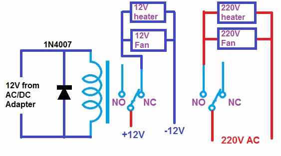
The switching of the 12V DC and the 220V AC is done separately by the two sets of N/O and N/C contacts.
Please refer to my previous diagram again. It clearly shows how the two sets of contacts are used for switching the 12V DC and the 220V AC separately for the separate heaters and fans, as required by you.
Let me know if you have more doubts.
I have been looking for an automatic transfer switch for a 2 kW solar system, which switches a load of max 3kVA from inverter to mains voltage once the batteries are low, and re-connects the inverter once the batteries are fully charged, thus giving the battery bank a healthy charge cycle before re-engaging. I have found the ideal switch on ebay
A friend suspected, that because of the very short switching time the magnetic field of a motor could not drop sufficiently and, should the inverter and mains phases not be in sequence, the motor could be damaged due to back rmf voltages. This does not mean much to me. Therefore, could you pleae enlighten me and tell me wheteher my friend’s concerns are justified? mmany thanks, Volker
Yes, that’s correct. The phase sequence should be perfectly matched between the inverter AC output and the mains AC output
Please draw an automatic ac dc changeover circuit