In this post I have explained how to generate sine wave pulse-width-modulation or SPWM through Arduino, which can be used for making a pure sine wave inverter circuit or similar gadgets.
The Arduino code is developed by me, and it is my first Arduino code, ...and it looks pretty good 🙂
What is SPWM
I have already explained how to generate SPWM using opamps in one of my earlier articles, you could go through it for understanding how it can be created using discrete components and regarding its importance.
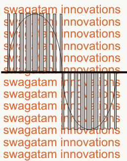
Basically, SPWM which stands for sine wave pulse width modulation, is a type of pulse modulation where the pulses are modulated to simulate a sinusoidal waveform, so that the modulation is able to attain properties of a pure sine wave.
To implement a SPWM the pulses are modulated with an initial narrower widths which gradually get broader at the center of the cycle, and finally end being narrower at the end to finish the cycle.
To be more precise, the pulses begin with narrowest widths which gradually get broader with each subsequent pulses, and gets broadest at the center pulse, after this, the sequence continues on but with an opposite modulation, that is the pulses now gradually begin getting narrower until the cycle finishes.
Video Demo
This constitutes one SPWM cycle, and this repeats throughout at a particular rate as determined by the application frequency (usually 50Hz or 60Hz). Typically, SPWM is used for driving power devices such as mosfets or BJTs in inverters or converters.
This special modulation pattern ensures that the frequency cycles are executed with a gradually changing average voltage value (also called the RMS value) , instead of throwing sudden Hi/low voltage spikes as normally witnessed in flat square wave cycles.
This gradually modifying PWMs in a SPWM is purposely enforced so that it closely replicates the exponentially rising/falling pattern of a standard sinewaves or sinusoidal waveform, hence the name sinewave PWM or SPWM.
Generating SPWM with Arduino
The above explained SPWM can be easily implemented using a few discrete parts, and also using Arduino which will probably enable you to get more accuracy with the waveform periods.
The following Arduino code can be used for implementing the intended SPWM for a given application.
Gosh!! that looks too big, if you know how to shorten it, you may certainly feel free to do it at your end.
UPDATE: Get this Improved Arduino SPWM Code
// By Swagatam (my first Arduino Code)
 void setup(){
 pinMode(8, OUTPUT);
 pinMode(9, OUTPUT);
 }
 void loop(){
 digitalWrite(8, HIGH);
 delayMicroseconds(500);
 digitalWrite(8, LOW);
 delayMicroseconds(500);
 digitalWrite(8, HIGH);
 delayMicroseconds(750);
 digitalWrite(8, LOW);
 delayMicroseconds(500);
 digitalWrite(8, HIGH);
 delayMicroseconds(1250);
 digitalWrite(8, LOW);
 delayMicroseconds(500);
 digitalWrite(8, HIGH);
 delayMicroseconds(2000);
 digitalWrite(8, LOW);
 delayMicroseconds(500);
 digitalWrite(8, HIGH);
 delayMicroseconds(1250);
 digitalWrite(8, LOW);
 delayMicroseconds(500);
 digitalWrite(8, HIGH);
 delayMicroseconds(750);
 digitalWrite(8, LOW);
 delayMicroseconds(500);
 digitalWrite(8, HIGH);
 delayMicroseconds(500);
 digitalWrite(8, LOW);
 //......
 digitalWrite(9, HIGH);
 delayMicroseconds(500);
 digitalWrite(9, LOW);
 delayMicroseconds(500);
 digitalWrite(9, HIGH);
 delayMicroseconds(750);
 digitalWrite(9, LOW);
 delayMicroseconds(500);
 digitalWrite(9, HIGH);
 delayMicroseconds(1250);
 digitalWrite(9, LOW);
 delayMicroseconds(500);
 digitalWrite(9, HIGH);
 delayMicroseconds(2000);
 digitalWrite(9, LOW);
 delayMicroseconds(500);
 digitalWrite(9, HIGH);
 delayMicroseconds(1250);
 digitalWrite(9, LOW);
 delayMicroseconds(500);
 digitalWrite(9, HIGH);
 delayMicroseconds(750);
 digitalWrite(9, LOW);
 delayMicroseconds(500);
 digitalWrite(9, HIGH);
 delayMicroseconds(500);
 digitalWrite(9, LOW);
 }
 //-------------------------------------//
How the Code Works
So here in this Arduino program, we are making SPWM which is sinusoidal pulse width modulation. We do this to create a kind of waveform that looks like a sine wave but is made using square pulses of different widths.
We start with the setup part like this:
void setup(){

pinMode(8, OUTPUT);

pinMode(9, OUTPUT);

}
This above code is just saying to Arduino that pin 8 and pin 9 both will be output pins. We will send HIGH and LOW signals from them. This setup runs only one time when Arduino starts.
Then we move to the loop part. Loop means everything inside it will run again and again forever.
void loop(){Now inside this loop, first we start giving SPWM pulses from pin 8. The idea is to start with small pulses, increase them step by step to peak value and then reduce again to small.
We do this:
digitalWrite(8, HIGH);

delayMicroseconds(500);

digitalWrite(8, LOW);

delayMicroseconds(500);
This gives a thin pulse of 500 microsecond ON and 500 microsecond OFF. It is like sine wave just starting from zero.
Then:
digitalWrite(8, HIGH);

delayMicroseconds(750);

digitalWrite(8, LOW);

delayMicroseconds(500);
This one is fatter than before meaning sine wave is going higher.
Then:
digitalWrite(8, HIGH);

delayMicroseconds(1250);

digitalWrite(8, LOW);

delayMicroseconds(500);
Now pulse is even more fat. So sine wave is now rising more.
Then this:
digitalWrite(8, HIGH);

delayMicroseconds(2000);

digitalWrite(8, LOW);

delayMicroseconds(500);
This is the maximum peak pulse. So we are at top of sine wave.
After this we begin going down.
digitalWrite(8, HIGH);

delayMicroseconds(1250);

digitalWrite(8, LOW);

delayMicroseconds(500);
Then:
digitalWrite(8, HIGH);

delayMicroseconds(750);

digitalWrite(8, LOW);

delayMicroseconds(500);
And finally:
digitalWrite(8, HIGH);

delayMicroseconds(500);

digitalWrite(8, LOW);
So this above series of HIGH and LOW signals from pin 8 makes one full sine cycle using pulse widths. This is one full SPWM cycle for pin 8.
Now we do the exact same thing for pin 9, like this:
digitalWrite(9, HIGH);

delayMicroseconds(500);

digitalWrite(9, LOW);

delayMicroseconds(500);

digitalWrite(9, HIGH);

delayMicroseconds(750);

digitalWrite(9, LOW);

delayMicroseconds(500);

digitalWrite(9, HIGH);

delayMicroseconds(1250);

digitalWrite(9, LOW);

delayMicroseconds(500);

digitalWrite(9, HIGH);

delayMicroseconds(2000);

digitalWrite(9, LOW);

delayMicroseconds(500);

digitalWrite(9, HIGH);

delayMicroseconds(1250);

digitalWrite(9, LOW);

delayMicroseconds(500);

digitalWrite(9, HIGH);

delayMicroseconds(750);

digitalWrite(9, LOW);

delayMicroseconds(500);

digitalWrite(9, HIGH);

delayMicroseconds(500);

digitalWrite(9, LOW);

}
So finally, this whole thing is a simple way to generate sine wave shaped signals using Arduino and square wave pulses of changing width.
In the next post I'll explain how to use the above Arduino based SPWM generator to make a pure sinewave inverter circuit....keep reading!


Questions & Answers
Hello sir,
Thank you for such wonderful information. Can you please help me with generating 3phase SPWM waveforms having control over frequency from 10Hz to 800Hz
Thank you Rishi,
You can try the last circuit from the following article. You can customize the frequencies by appropriately adjusting the timing components of the IC 556.
https://www.homemade-circuits.com/how-to-generate-sinewave-pwm/
Thank you sir for your reply
I have tried above article but i need to use arduino to generate 3 phase SPWM waveforms what modification do i need to make in code given in this article. And how can i have control over frequency of this waveforms. Can you please help me with it and to create proteus simulation. I will be very thankfull
Hi Rishi, sorry, I don’t have a 3 phase spwm generator circuit, however I have some idea how to chop the low side mosfets of a normal 3 phase inverter with spwm to generate a 3 phase sine waveform at the inverter output.
good job welldon
Good day
this is my first post.
Thanks so much for all the work that has been done with this Arduino project.
I was wondering about the pins to connect to the oscilloscope for checking the pattern.
It seems that I get the best pettern from pin 8 for the original sketch, but the improved sketch seems to be pin 9.
Kind regards.
JB
You are most welcome!
I my code you can connect either pin8 or pin9 both will give similar SPWM waveform since both have have identical set of codes.
I am not sure about the code written by Atton
arduino inverter with 4 mosfet transistor battery 12v dc output 220 v ac
give me the simulation in proteus with code if you can with pleasure…
thanks.
hello engr. Swagatam!
I really appreciate this post. But I have a question regarding soft-start functionality.
is there any available code for implementing soft-start functionality to control the ontime switching of the SPWM ?
Please i will be very glad if this can be included with the code.
Thank you.
Thank you Kingsley, I really wish I could help, however I do not have much idea regarding how to implement a soft start on the PWMs. I think you can take this issue to Arduino.cc forums and ask them for a solution…. they might help you!
Hi Mr. Swagatam,
is that posibble to apply your code for 3 phase SPWM with small changes? I mean, by adding new pwm pins to the code, like pin 11, pin 6, pin 5, and pin 3. So there is 6 sPWMpin for 3 phase SPWM inverter. Is that possible? I’ve found an article that mentioned Arduino Uno can’t generate 6 pwm signal because one pin is used for interrupt .
Hi Fitrah, If you generate them with proper 120 degrees separation then it will work, however I am not sure exactly which Arduino board would be able to implement this.
Thanks for your reply, Mr. Swagatam.
So about the 120 degrees phase shift, an article mentioned that to get 120 degrees phase shift, the second signal must start 6.66 ms after the first signal, and the third signal must start 6.66 ms after the second signal. So, should i put some delay into the code? Or could you show me the better way?
Best Regards.
yes that’s right, but I don’t remember the calculations for the frequency delay across the the 3 phase waves, if you are sure you can try implementing the mentioned amount of delay and check the response.
Thank You Mr. Swagatam.
I appreciate your help, thank you very much. I’ll try the method. And soon i’ll post the code through the comments to make sure the program is correct or not, so you or the readers can improve it to better code.
You are welcome Fitrah!
Hi Swag.
i just try to upload your code to my arduino UNO. in the lcd i can get on full black digits only. this code is correct or it has to modify?
regards.
Hi Paaker, all Arduino codes published in this website are perfect and tested….however since the author of the above circuit is not associated at the moment so troubleshooting your issue will be difficult for me….but you can put this question in any online Arduino forum….they might help to solve it for you….
Thanks Swag.
Compacted code:
/* This code was based on Swagatam SPWM code with changes made to remove errors. Use this code as you would use any other Swagatam’s works.
Atton Risk 2017 + Yves.Hacha @ tresco.eu, 22/6/2018: more compacte code */
// choose 1 of the SPWM tables below:
const int sPWMArray[] = {500,500,750,500,1250,500,2000,500,1250,500,750,500,500}; // this is the array with the 50Hz SPWM values; change them at will
// const int sPWMArray[] = {416,416,625,416,1041,416,1666,416,1041,416,625,416,416,7}; // use this table to obtain 60Hz
// const int sPWMArray[] = {124,464,245,349,359,244,463,153,552,80,630,29,1880,29,630,80,552,153,463,244,359,349,245,464,124,586}; // more detailed 50Hz SPWM
const int sPWMArrayValues = sizeof(sPWMArray)/sizeof(sPWMArray[0]);
// The pins
const int sPWMpin1 = 10;
const int sPWMpin2 = 9;
void setup()
{
pinMode(sPWMpin1, OUTPUT);
pinMode(sPWMpin2, OUTPUT);
}
void loop()
{
const int pinArray[] = {sPWMpin1,sPWMpin2};
for (int pin(0); pin<2; pin++)
{
bool sPWMpinStatus = true;
for(int i(0); i<sPWMArrayValues; i++)
{
digitalWrite(pinArray[pin], (sPWMpinStatus)?HIGH:LOW);
delayMicroseconds(sPWMArray[i]);
sPWMpinStatus = !sPWMpinStatus;
}
digitalWrite(pinArray[pin], LOW);
}
}
Thank you Yves, I would appreciate if you could tell us regarding the errors that you have removed in your code.
1. offer 3 separate tables to choose from
2. automatically get the correct PWM table size
3. reuse the first half sinewave loop code also for the second half sinewave loop
4. make sure each output pin stays low during the time that the other pin is ‘pulsing’
(I’m sorry to see that the indentation of the code got lost while pasting…)
OK Great thanks very much! And will the indentation issue cause any compiling errors?
No, not at all!
OK great!
Use
const int sPWMArrayValues = sizeof(sPWMArray)/sizeof(sPWMArray[0])
to automatically get the table size, in stead of
const int sPWMArrayValues = 13; // You need this since C doesn’t give you the length of an Array
thank you for the suggestion Yves, appreciate it very much!
Hi sir,
im using 14V dc supply. By using your code, is it possible to get 230V or 240V?
Hi Uthaya, You can get any desired output voltage depending on your transformer specification, Here the primary must be selected by calculating the ON time from the Arduino, check ratio of HIGH and LOW outputs across each channel from the Arduino, divide the total numbers of Highs + Lows in the code with number of Highs, now divide the battery voltage with this result to get the transformer primary voltage spec.
sir im using your code in H bridge, mosfet irf520. my out is very less. how to solve?
Please provide all the details, schematic diagram, transformer rating, battery specs…etc
Circuit is H bridge design, using 4 mosfet. Mosfet model are irf520. Transformer 12/240V 3A. Input is 14Vdc. Currently im supplying input from dc supply not a battery.
I only getting output around 5V before connect to transformer.
Can I get your email. So i can send my circuit diagram and some details
hi, can you make the code that can change the frequency ( 0 – 50Hz), shift, triangular wave, and modulation. thanks
Hi, getting customized codes is presently a premium offer, and you may have to pay for it.
Yes, I think that the array count on each waveform cycle should be an even number.
I’ve had some more thoughts on this, and I now feel that there should be a slight delay between the 2 halves of the waveform, so I suggest the following:
sPWMArray[] = {496,500,750,500,1250,500,2000,500,1250,500,750,500,496,8}
As you can see, I have reduced the start and end ON times by 4uS to provide an 8uS guard band, so that there is no chance of both transistors being on at the same time.
When I have built the full inverter, I will experiment further with the delay in order to optimise the sine wave shape.
Incidentally, if a 60Hz version is required, scaling the numbers gives the following:
sPWMArray[] = {416,416,625,416,1041,416,1666,416,1041,416,625,416,416,7}
OK, that makes sense, I indeed appreciate your modifications and inputs.
however according to me the number of arrays which form the “PWM pillars” across the AC cycle waveforms, will actually not affect the sinewave outcome by much, if their’s any other adverse effect, then I am not sure about it.
and as far as the the “dead time” is concerned, you will see that the code on each channel ends with a “low” to be precise with this value: digitalWrite(8, LOW)
so the “low” makes sure that during the transition both the devices are completely OFF, although the delay on this value can be perhaps increased to some higher level to ensure a better dead time delay…this is what I have assumed while designing the code, not sure whether this will be effective during the actual implementation or not 🙂
Having built a low power version of the inverter, I found that it was difficult to filter the AC output. So after more research I have come up with a version using more pulses (use in the sketch above):
const int sPWMArray[] = {124,464,245,349,359,244,463,153,552,80,630,29,1880,29,630,80,552,153,463,244,359,349,245,464,124,586}; // This is the array with the SPWM values
const int sPWMArrayValues = 26; // You need this since C doesn’t give you the length of an Array
You’ll notice that this varies the delays as well as pulse widths. Also note the much longer delay at the end of the sequence to provide a long OFF time at the polarity switchover. The sequence was derived using Don Lancaster’s Guru’s Lair Magic Sinewaves Library:
I’m currently using a series 100uH inductor on the transformer output and a 1uF X2 capacitor. This helps, but I think it needs a bigger inductor, so I have ordered a 560uH.
thank you so much for your time and work! great job
you are welcome!
Thank you very much Andy, I appreciate your research, hope the other readers will find this useful, and please keep us updated as you move deeper with this project
Swagatam, thanks for your work on this project. Your code at the top of this page produces the correct waveform; whereas the “enhanced performance” version below it does not. Unfortunately I’m not sufficiently proficient with Arduino coding to see how to fix it. But as your less elegant solution takes up so little space, I’m happy to use that.
By experimentation, I found that by adding a ,0 to the end of the sPWMArray and changing the sPWMArrayValues to 14, the code worked as it should. I suspect that the problem was that each loop increments by 2 (1 HIGH, 1 LOW), so having an odd number in the array caused it to go out of step.
Thank you Andy, I am glad I could help!
Can you please explain a little more regarding the “odd number” issue, do you mean to say the array count on each waveform cycle should be ideally an even number?
Thanks for visiting my site and enlightening us all.
Nice work one Swagatem, you have officially made it to my Top 5 911 Engineering List, I appreciate all your hard work to this blog.
I have 2 questions:
1. Will the circuit give regulated VAC output constantly?
2. How can i better the circuit to carry things like fan etc?
Thanks again
Thanks Miebaka, I am so glad you liked my site!
Since the PWM delays would be constant from the Arduino or may be tweaked as per the users preference and transformer winding rating, the output can be expected to be very accurate and no external regulator would be required for fixing the RMS.
as for the fan operation, a properly calculated filter circuit at the output of the trafo will be quite sufficient to allow you to operate inductive loads efficiently.