This article explains a simple pure sine wave inverter circuit using Arduino, which could be upgraded to achieve any desired power output as per the user's preference.
Circuit Operation
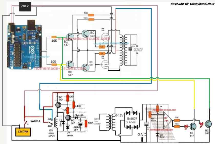
In the last article I have explained how to generate sine wave pulse width modulation or SPWM though Arduino, we are going to use the same Arduino board to make the proposed simple pure sine wave inverter circuit. The design is actually extremely straightforward, as shown in the following figure.
You just have to program the arduino board with the SPWM code as explained in the previous article, and hook it up with some of the external devices.
You may also want to read: H-Bridge Sine Wave Inverter Circuit
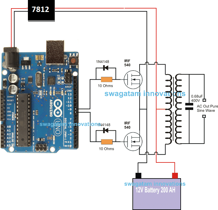
Pin#8 and pin#9 generate the SPWMs alternately and switch the relevant mosfets with the same SPWM pattern.
The mosfst in turn induce the transformer with high current SPWM waveform using the battery power, causing the secondary of the trafo to generate an identical waveform but at the mains AC level.
The proposed Arduino inverter circuit could be upgraded to any preferred higher wattage level, simply by upgrading the mosfets and the trafo rating accordingly, alternatively you can also convert this into a full bridge or an H-bridge sine wave inverter
Powering the Arduino Board
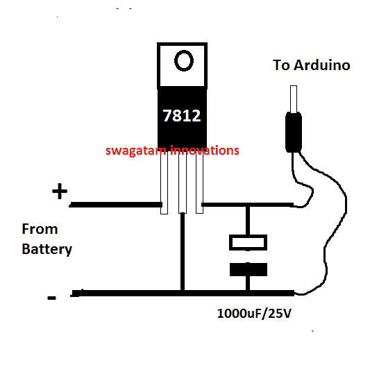
In the diagram the Arduino board could be seen supplied from a 7812 IC circuit, this could be built by wiring a standard 7812 IC in the following manner. The IC will ensure that the input to the Arduino never exceeds the 12V mark, although this might not be absolutely critical, unless the battery is rated over 18V.
If you have any questions regarding the above SPWM inverter circuit using a programmed Arduino, please feel free to ask them through your valuable comments.
Waveform Images for Arduino SPWM
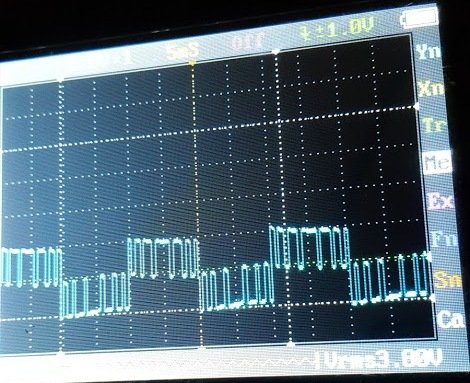
Image of SPWM waveform as obtained from the above Arduino inverter design (Tested and Submitted By Mr. Ainsworth Lynch)
UPDATE:
Using BJT Buffer Stage as Level Shifter
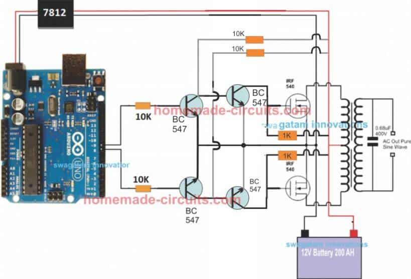
Since an Arduino board will produce a 5V output, it may not be an ideal value for driving mosfets directly.
Therefore an intermediate BJT level shifter stage may be required for raising the gate level to 12V so that the mosfets are able to operate correctly without causing unnecessary heating up of the devices,. The updated diagram (recommended) can be witnessed below:
UPDATE: Get this Improved Arduino SPWM Code
Program Code for the above Arduino Sine Wave Inverter Circuit
// By Swagatam
void setup(){
pinMode(8, OUTPUT);
pinMode(9, OUTPUT);
}
void loop(){
digitalWrite(8, HIGH);
delayMicroseconds(500);
digitalWrite(8, LOW);
delayMicroseconds(500);
digitalWrite(8, HIGH);
delayMicroseconds(750);
digitalWrite(8, LOW);
delayMicroseconds(500);
digitalWrite(8, HIGH);
delayMicroseconds(1250);
digitalWrite(8, LOW);
delayMicroseconds(500);
digitalWrite(8, HIGH);
delayMicroseconds(2000);
digitalWrite(8, LOW);
delayMicroseconds(500);
digitalWrite(8, HIGH);
delayMicroseconds(1250);
digitalWrite(8, LOW);
delayMicroseconds(500);
digitalWrite(8, HIGH);
delayMicroseconds(750);
digitalWrite(8, LOW);
delayMicroseconds(500);
digitalWrite(8, HIGH);
delayMicroseconds(500);
digitalWrite(8, LOW);
//......
digitalWrite(9, HIGH);
delayMicroseconds(500);
digitalWrite(9, LOW);
delayMicroseconds(500);
digitalWrite(9, HIGH);
delayMicroseconds(750);
digitalWrite(9, LOW);
delayMicroseconds(500);
digitalWrite(9, HIGH);
delayMicroseconds(1250);
digitalWrite(9, LOW);
delayMicroseconds(500);
digitalWrite(9, HIGH);
delayMicroseconds(2000);
digitalWrite(9, LOW);
delayMicroseconds(500);
digitalWrite(9, HIGH);
delayMicroseconds(1250);
digitalWrite(9, LOW);
delayMicroseconds(500);
digitalWrite(9, HIGH);
delayMicroseconds(750);
digitalWrite(9, LOW);
delayMicroseconds(500);
digitalWrite(9, HIGH);
delayMicroseconds(500);
digitalWrite(9, LOW);
}
//-------------------------------------//
Video Clip
Parts List
All resistors are 1/4 watt, 5% CFR
- 10K = 4
- 1K = 2
- BC547 = 4nos
- Mosfets IRF540 = 2nos
- Arduino UNO = 1
- Transformer = 9-0-9V/220V/120V current as per requirement.
- Battery = 12V, Ah value as per requirement
Delay Effect
To ensure that the mosfet stages initiate with a delay during the Arduino booting or start up, you may modify left side BC547 transistors into delay ON stages, as shown below. This will safeguard the mosfets and prevent them from burning during power switch ON Arduino booting.
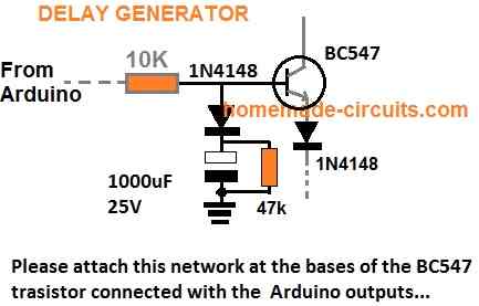
FOR INCREASING THE DELAY YOU CAN INCREASE THE 10K VALUE TO 100K
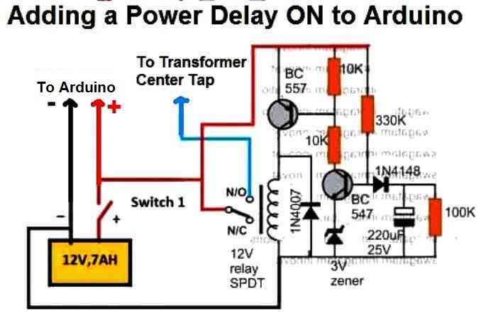
A More Reliable Delay ON Timer
If you are not comfortable with the response of the above passive delay ON timer circuit, you can employ the following configuration using BJTs and a relay. This design is extremely reliable and will effectively protect your Arduino and the inverter from burning due to a malfunctioning delay effect.
Just add this to the above inverter configuration.
Adding an Automatic Voltage Regulator
Just like any other inverter the output from this design can rise to unsafe limits when the battery is fully charged.
To control this an automatic voltage regulator could be employed as shown below.
The BC547 collectors should be connected to the bases of the left side BC547 pair, which are connected to the Arduino via 10K resistors.
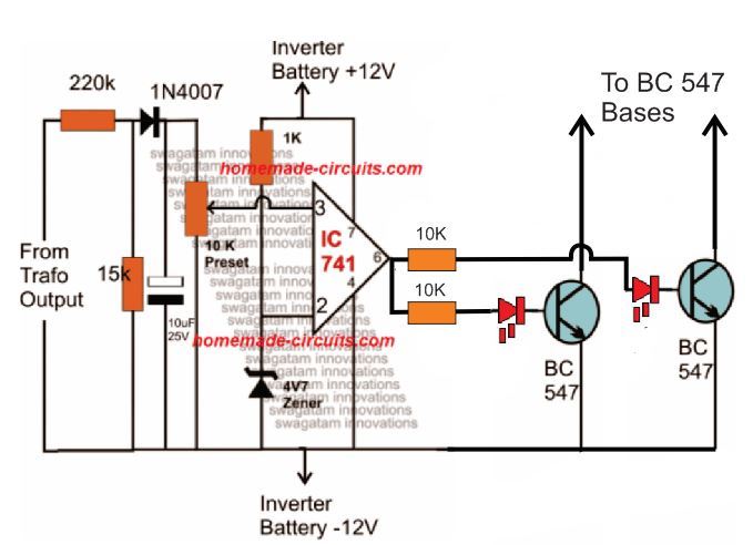
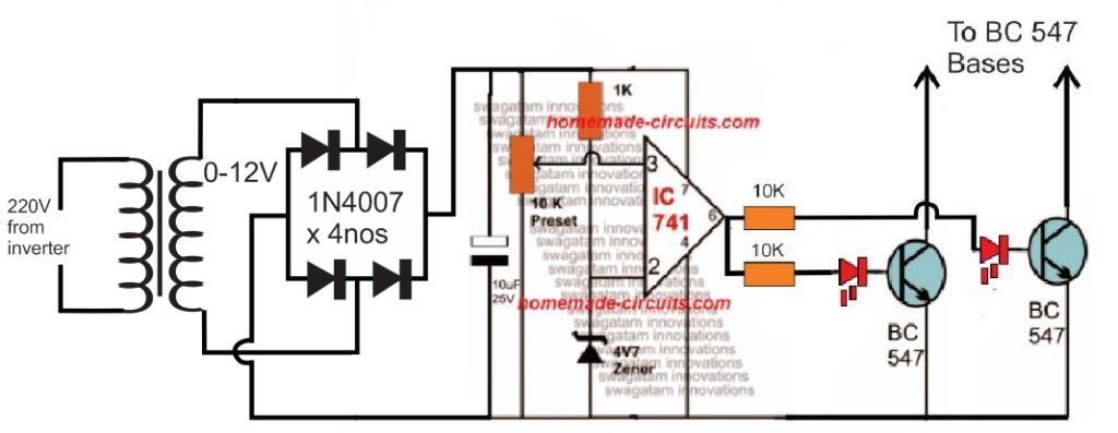
For an isolated version of voltage correction circuit we can modify the above circuit with a transformer, as shown below:
How to Setup
To set up the automatic voltage correction circuit, feed a stable 230V or 110V as per your inverter specs to the input side of the circuit.
Next, adjust the 10k preset carefully such that the red LEDs just light up. That's all, seal the preset and connect the circuit with the above Arduino board for implementing the intended automatic output voltage regulation.
The Complete Circuit Diagram
The complete diagram using the automatic voltage regulator and the delay ON timer would look like this:


Questions & Answers
Hello engineer. I hope God gives you absolute health for providing such practical tools without your expectations. Thank you
engineer. I wanted to see if it was possible to design and build a practical circuit for detecting a fault. Thank you.
Thanks Shahin, actually your digital multimeter and oscilloscope are the best gadgets for detecting faults in a circuit…
Or you can explain me what type of circuit are you referring to?
thans but ineed a circuit that can charge spiro battery
Hello, don’t be shy, Mr. Engineer, thank you for your quick response. I think the multimeter you mentioned is a good solution. Thank you. I wanted to know if you are also working on metal detector projects. If so, is it possible for you to post a schematic of a practical and accurate metal detector? Thank you again for all your efforts.
Thank you Shahin, for your feedback….I already have a few good article on metal detectors, you can check them out here:
https://www.homemade-circuits.com/vehicle-body-metal-detector-circuit/
https://www.homemade-circuits.com/how-to-make-simple-metal-detector/
https://www.homemade-circuits.com/stud-finder-circuit-find-hidden-metals-inside-walls/
Hi.
Well, I am an old user of your site and visiting you after a long time and happy to see you are still serving humanity.
I have both a 48v and 12v, iron core transformers salvaged from old UPS (imported and sinewave, APC) but never used. Now intend to build a pure sinewave inverter and want to connect it with a 585w, 48v solar plate however I have certain problems:
1). The voltage of Solar plate can be between 36v to 60v (rated 48v, passing clouds etc.), so the inverter’s input can accommodate such voltage fluctuations.
2). I intend to directly attach inverter with Solar plate
3). Presently my load is about a total of 120 watts for two BLDC based electric fans, 220v (assumed to safe electricity, these fans have an electronic circuit attached above, which seems to convert AC to pulse mode DC and has remove controls to operate at 7 deifferent speeds). However, I intend to use a pc computer (450w) as well, in future so total watts can be around 600w or more.
4). The inverter can shutdown safely if input voltage is below a certain voltage i.e. 36v
5). The inverter also shutdowns safely if overloaded, load greater than a “preset” watt consumption i.e. greater then 200 or 500 watts.
6). Output needs to pure sinewave.
7). A simple way to calculate and accommodate, if I need to change the input voltage later on i.e. 12v or 24v etc.
8). Power FET’s can be used as low-cost variants, so build is cheaper.
9). The 12v transformer seems to be center tapped but other is not. So please suggest how to use transformers in either case i.e. a center tapped and without one or two wires only.
Please suggest me some circuits in light of above. If circuits are already tested then it shall be better otherwise, I may experiment. Moreover, using latest tech i.e. Arduino etc. if circuit can be reduced then it’s much better. Lower troubleshooting, and may have a chance to work first time. Moreover, I don’t need batteries (very expensive), just to utilize day light to save some grid electricity billing.
I have experience building a lot of analog circuits and also knows programming though never created a digital electronic circuit before.
Regards
Hi, I think you can start the project with the circuit design as explained in the following article.
However for the transformer you will have to go with an iron cored toroidal transformer, rated at 0-36V 10 amps.
https://www.homemade-circuits.com/making-an-egs002-equivalent-board-using-arduino/
To change the 12V/24V voltage rating you will have to change the transformer accordingly.
If you want a ferrite based design then you may have to do some calculations. I can help with that also…
Hi, thanks for your detailed explanation about the project…I am currently working on your project and it may take sometime to finish the basic design, which we can later on modify according to your specifications…I will let you know once it is done…
Please do raspberry pi pico own for us.
Sure, thank you, I will try to include raspberry pi pico projects also in this blog soon
Please I am still waiting in eagerness
Thank you for your request, Actually currently I am busy doing youtube videos so not getting time for your projects, but I have noted it and I will try to start it posting soon…
Hello,
Can I use this circuit for a 110W fan? (inductive load)
I have a transformer 2x9v – 160VA
Thanks
Sure, you can operate a 220V fan, but after adding an LC filter at the output of the transformer…and also make sure to add snubbers across the MOSFET gates…
Hi Swagatam, When we compare the above ardunio waveform with the ideal AC waveform, do you think that Ardunio output is exactly the equivalent? I will use this for the combi boiler. So is it possible to say that they are compatible in the aspect of the waveform since the boiler circuits may be sensitive?
Hi Suat, yes the microseconds are dimensioned precisely to match a standard mains AC waveform, however for more accurate structure you can take the help of the following calculator:
https://www.homemade-circuits.com/sine-table-calculator-for-spwm-arduino-code/
plse help me Hex file of Aduino puresine inverter ,i havent skils for convert codes to Hex file
Here’s the HEX conversion for the Arduino code:
:100000000C945C000C9479000C9479000C947900A9
:100010000C9479000C9479000C9479000C9479007C
:100020000C9479000C9479000C9479000C948C0158
:100030000C9479000C9479000C9479000C9479005C
:100040000C9442010C9479000C9479000C94790082
:100050000C9479000C9479000C9479000C9479003C
:100060000C9479000C947900000000080002010053
:100070000003040700000000000000000000000072
:10008000250028002B0000000000240027002A0083
:10009000040404040404040402020202020203032E
:1000A0000303030301020408102040800102040836
:1000B000102001020408102011241FBECFEFD8E049
:1000C000DEBFCDBF11E0A0E0B1E0E4ECF4E002C09F
:1000D00005900D92A631B107D9F721E0A6E1B1E074
:1000E00001C01D92A232B207E1F70E94F7010C9401
:1000F00060020C94000090E0FC01EC55FF4F24914D
:1001000080579F4FFC018491882399F090E0880FDD
:10011000991FFC01EA57FF4FA591B491FC01E458E7
:10012000FF4F859194918FB7F894EC91E22BEC936B
:100130008FBF089590E0FC01E859FF4F2491FC0126
:10014000EC55FF4F3491FC01E057FF4FE491EE2353
:10015000C9F0222339F0233001F1A8F4213019F13C
:10016000223029F1F0E0EE0FFF1FE458FF4FA59178
:10017000B4918FB7F894EC91611126C030953E236D
:100180003C938FBF08952730A9F02830C9F0243060
:1001900049F7809180008F7D03C0809180008F7728
:1001A00080938000DFCF84B58F7784BDDBCF84B5AB
:1001B0008F7DFBCF8091B0008F778093B000D2CF3E
:1001C0008091B0008F7DF9CF3E2BDACF1F93CF9374
:1001D000DF93182FEB010E947B00209739F460E039
:1001E000812FDF91CF911F910C949A00CF3FD105C1
:1001F00011F461E0F5CFE12FF0E0E859FF4FE49111
:10020000E33031F140F4E130B1F0E230E1F0C038F8
:10021000D1057CF7E4CFE73029F1E83059F1E4303B
:10022000B1F780918000806280938000D0938B0032
:10023000C0938A0004C084B5806884BDC7BDDF91C7
:10024000CF911F91089584B5806284BDC8BDF7CF5A
:1002500080918000806880938000D0938900C09353
:100260008800EDCF8091B00080688093B000C0938B
:10027000B300E5CF8091B00080628093B000C0935E
:10028000B400DDCF1F920F920FB60F9211242F935F
:100290003F938F939F93AF93BF9380911E01909153
:1002A0001F01A0912001B091210130911D0123E097
:1002B000230F2D3758F50196A11DB11D20931D0167
:1002C00080931E0190931F01A0932001B093210100
:1002D0008091190190911A01A0911B01B0911C010C
:1002E0000196A11DB11D8093190190931A01A0934D
:1002F0001B01B0931C01BF91AF919F918F913F91D2
:100300002F910F900FBE0F901F90189526E8230F86
:100310000296A11DB11DD2CF1F920F920FB60F9260
:1003200011242F933F934F935F936F937F938F93FA
:100330009F93AF93BF93EF93FF9370E060E089E0EA
:100340000E94E60070E060E08AE00E94E60083EC34
:1003500090E00197F1F78091180181113AC0E09186
:100360001601F0911701E050FF4F608170E089E0C5
:100370000E94E60070E060E08AE00E94E600809162
:100380001601909117010196909317018093160121
:100390008091160190911701459754F01092170122
:1003A000109216018091180191E08927809318011D
:1003B000FF91EF91BF91AF919F918F917F916F913D
:1003C0005F914F913F912F910F900FBE0F901F9013
:1003D000189570E060E089E00E94E600E091160167
:1003E000F0911701E050FF4F608170E0C5CF789425
:1003F00084B5826084BD84B5816084BD85B582602A
:1004000085BD85B5816085BD80916E0081608093DA
:100410006E00109281008091810082608093810043
:100420008091810081608093810080918000816053
:10043000809380008091B10084608093B1008091AE
:10044000B00081608093B00080917A0084608093D6
:100450007A0080917A00826080937A0080917A009D
:10046000816080937A0080917A00806880937A001E
:100470001092C10089E00E947B008AE00E947B000C
:10048000109280001092810088EB93E09093890095
:1004900080938800809181008860809381008091A2
:1004A000810082608093810080916F0082608093E0
:1004B0006F00C0E0D0E02097F1F30E940000FBCF76
:0404C000F894FFCFDE
:1004C4008093A7B9CADAE7F1F9FDFFFDF9F1E7DA9C
:0604D400CAB9A7938000E5
:00000001FF
at 12v input my output voltage is not going above 80-90volts . when I increased the input voltage around 30v my drain to source diode burned (i was using 4148 diode 😐 ) , can I use uf4007 as a flyback diode . I am using a push pull diver with pnp and npn for gate driving . I have used your gate driving method too , but my output never goes over 90volts . I have also tried a different transformer but same problem . not added the feedback circuit yet . can you help me please . I also tried using a 12v zener to protect the gate .
If you have used the second diagram with 4 BJTs, exactly as shown in the above article, then definitely it is the problem of your transformer.
Make sure the transformer primary is rated around 7-0-7V or 9-0-9V, and not 12-0-12V.
You can use freewheeling diodes across the transformer winding, between center tap and the outer taps. UF4007 is OK.
Please try with a 12v supply only, do not increase it.
sir thank you for the response . sir I have tried using a 9-0-9 transformer according to you but the results are same . can you please help me with this , I have to submit this projects within a week .
Akash, that means something may be wrong either with your transformer or your meter. I think you should test it with an oscilloscope.
As you can see everything worked perfectly for my prototype. The 100 watt bulb illuminated fully, without dropping any output voltage.
Are you testing it with an output load or without load? What is the Ah rating of your battery, and current ratings of your transformer?
sir without load i am getting 100volts and with load its dropping . I am using a 3ampere power supply . sir I have seen people using a higher ampere transformer . should I go for that ? or should I go for higher amp power supply ?
Akash, Please try the following design and let me know the results, if you still see the same problem, then certainly your transformer could be the culprit:

Hi Bro
Thanks for sharing your experiences.
I’m really keen to know about 3 phases and the codes.
you mean 3 phases, but with how much votage?
110V or 380V
Thanks Bro, the voltage will depend on your choice, you can feed any desired DC voltage across the MOSFETs as per the load specifications…
1. anda menggunakan transformator jenis apa ? (inti besi, ferit, toroid) yang mana.
2. ideal waktu PWM berapa bagusnya ?
e-mail : fadhlyyy@yahoo.com
Iron core transformer is used in the above article.
For a ferrite core trafo you can use a pwm as high as 100kHz or above…
may you please explain the Arduino UNO code sir which used in it …….
Hello Anishka, you can refer to the following article for the full explanation:
https://www.homemade-circuits.com/arduino-spwm-generator-circuit/
sir maybe I supply Arduino from laptop ??
Yes, you can use the 5V from laptop USB to power your Arduino…
sir is that IRFZ44N mosfet use kar sakte ??
Yes, you can use IRFZ44 MOSFETs in the suggested design.