This article explains a simple pure sine wave inverter circuit using Arduino, which could be upgraded to achieve any desired power output as per the user's preference.
Circuit Operation
In the last article I have explained how to generate sine wave pulse width modulation or SPWM though Arduino, we are going to use the same Arduino board to make the proposed simple pure sine wave inverter circuit. The design is actually extremely straightforward, as shown in the following figure.
You just have to program the arduino board with the SPWM code as explained in the previous article, and hook it up with some of the external devices.
You may also want to read: H-Bridge Sine Wave Inverter Circuit
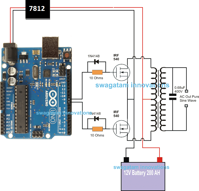
Pin#8 and pin#9 generate the SPWMs alternately and switch the relevant mosfets with the same SPWM pattern.
The mosfst in turn induce the transformer with high current SPWM waveform using the battery power, causing the secondary of the trafo to generate an identical waveform but at the mains AC level.
The proposed Arduino inverter circuit could be upgraded to any preferred higher wattage level, simply by upgrading the mosfets and the trafo rating accordingly, alternatively you can also convert this into a full bridge or an H-bridge sine wave inverter
Powering the Arduino Board
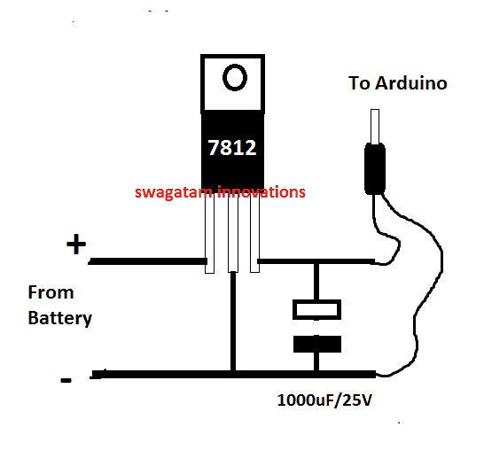
In the diagram the Arduino board could be seen supplied from a 7812 IC circuit, this could be built by wiring a standard 7812 IC in the following manner. The IC will ensure that the input to the Arduino never exceeds the 12V mark, although this might not be absolutely critical, unless the battery is rated over 18V.
If you have any questions regarding the above SPWM inverter circuit using a programmed Arduino, please feel free to ask them through your valuable comments.
Waveform Images for Arduino SPWM
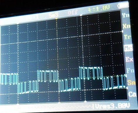
Image of SPWM waveform as obtained from the above Arduino inverter design (Tested and Submitted By Mr. Ainsworth Lynch)
UPDATE:
Using BJT Buffer Stage as Level Shifter
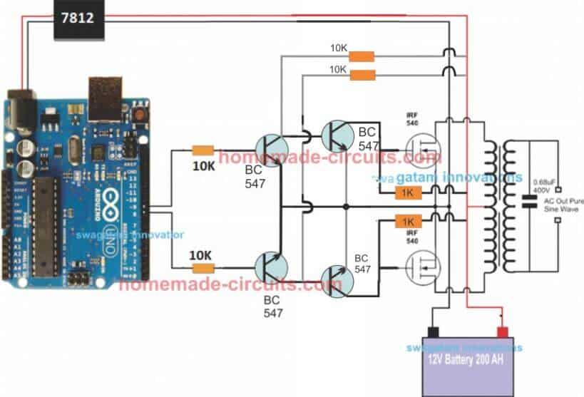
Since an Arduino board will produce a 5V output, it may not be an ideal value for driving mosfets directly.
Therefore an intermediate BJT level shifter stage may be required for raising the gate level to 12V so that the mosfets are able to operate correctly without causing unnecessary heating up of the devices,. The updated diagram (recommended) can be witnessed below:
UPDATE: Get this Improved Arduino SPWM Code
Program Code for the above Arduino Sine Wave Inverter Circuit
// By Swagatam
void setup(){
pinMode(8, OUTPUT);
pinMode(9, OUTPUT);
}
void loop(){
digitalWrite(8, HIGH);
delayMicroseconds(500);
digitalWrite(8, LOW);
delayMicroseconds(500);
digitalWrite(8, HIGH);
delayMicroseconds(750);
digitalWrite(8, LOW);
delayMicroseconds(500);
digitalWrite(8, HIGH);
delayMicroseconds(1250);
digitalWrite(8, LOW);
delayMicroseconds(500);
digitalWrite(8, HIGH);
delayMicroseconds(2000);
digitalWrite(8, LOW);
delayMicroseconds(500);
digitalWrite(8, HIGH);
delayMicroseconds(1250);
digitalWrite(8, LOW);
delayMicroseconds(500);
digitalWrite(8, HIGH);
delayMicroseconds(750);
digitalWrite(8, LOW);
delayMicroseconds(500);
digitalWrite(8, HIGH);
delayMicroseconds(500);
digitalWrite(8, LOW);
//......
digitalWrite(9, HIGH);
delayMicroseconds(500);
digitalWrite(9, LOW);
delayMicroseconds(500);
digitalWrite(9, HIGH);
delayMicroseconds(750);
digitalWrite(9, LOW);
delayMicroseconds(500);
digitalWrite(9, HIGH);
delayMicroseconds(1250);
digitalWrite(9, LOW);
delayMicroseconds(500);
digitalWrite(9, HIGH);
delayMicroseconds(2000);
digitalWrite(9, LOW);
delayMicroseconds(500);
digitalWrite(9, HIGH);
delayMicroseconds(1250);
digitalWrite(9, LOW);
delayMicroseconds(500);
digitalWrite(9, HIGH);
delayMicroseconds(750);
digitalWrite(9, LOW);
delayMicroseconds(500);
digitalWrite(9, HIGH);
delayMicroseconds(500);
digitalWrite(9, LOW);
}
//-------------------------------------//
Video Clip
Parts List
All resistors are 1/4 watt, 5% CFR
- 10K = 4
- 1K = 2
- BC547 = 4nos
- Mosfets IRF540 = 2nos
- Arduino UNO = 1
- Transformer = 9-0-9V/220V/120V current as per requirement.
- Battery = 12V, Ah value as per requirement
Delay Effect
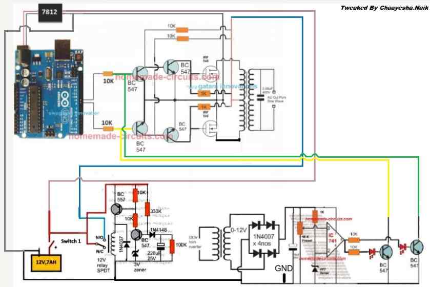
To ensure that the mosfet stages initiate with a delay during the Arduino booting or start up, you may modify left side BC547 transistors into delay ON stages, as shown below. This will safeguard the mosfets and prevent them from burning during power switch ON Arduino booting.
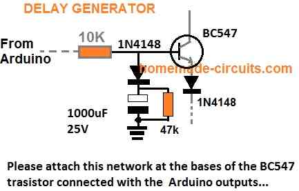
FOR INCREASING THE DELAY YOU CAN INCREASE THE 10K VALUE TO 100K
A More Reliable Delay ON Timer
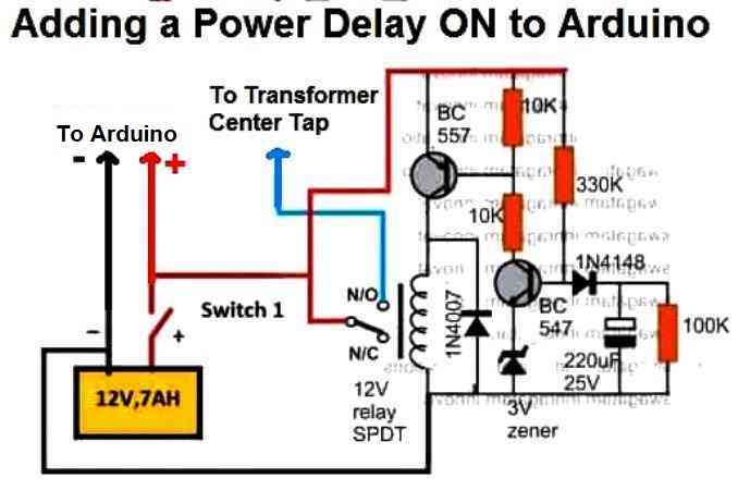
If you are not comfortable with the response of the above passive delay ON timer circuit, you can employ the following configuration using BJTs and a relay. This design is extremely reliable and will effectively protect your Arduino and the inverter from burning due to a malfunctioning delay effect.
Just add this to the above inverter configuration.
Adding an Automatic Voltage Regulator
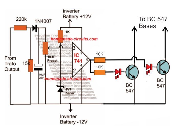
Just like any other inverter the output from this design can rise to unsafe limits when the battery is fully charged.
To control this an automatic voltage regulator could be employed as shown below.
The BC547 collectors should be connected to the bases of the left side BC547 pair, which are connected to the Arduino via 10K resistors.
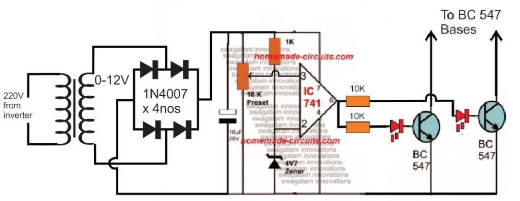
For an isolated version of voltage correction circuit we can modify the above circuit with a transformer, as shown below:
How to Setup
To set up the automatic voltage correction circuit, feed a stable 230V or 110V as per your inverter specs to the input side of the circuit.
Next, adjust the 10k preset carefully such that the red LEDs just light up. That's all, seal the preset and connect the circuit with the above Arduino board for implementing the intended automatic output voltage regulation.
The Complete Circuit Diagram
The complete diagram using the automatic voltage regulator and the delay ON timer would look like this:


Questions & Answers
Sir, what of feedback, isn't that and essential part in inverter operation?
Oluwole, feedback is not an essential part for an inverter, it's just an added feature.
If you have your transformer correctly matched with the battery then feedback won't be necessary
Hi Swagatam,
I have tried PWM charge controller using arduino and it is successful. Iam using it in my home generating 80 watts of power from 200 watts panel. I know its very poor.
BTW, I admire your works and I keep looking at your blogs very often.
I came across this very interesting circuit and I want to try this inverter.
Just to be sure, I have few 4905 PNP mosfets lying around from previous project, Can i use the same in your circuit? Source of mosfet connecting to Battery -ve and Drain of mosfet to transformer?
2. Transformer rating: secondary 12v-0-12v/15A, primary 220V. What will be my output power? is it 12×15=180 Watts? So if i increase the transformer rating to 30A can i get 360 watts of power? ofcourse with some 10-15% losses…
Hi Sham, if you are using an Arduino based controller and getting 80 watts from 200watts, then it's not worth using…or may be you haven't built it correctly, a linear IC circuit would give much better results than this.
as for the above Arduino sinewave inverter, yes it's indeed an interesting and handy little inverter which will give you pure sinewave just by hooking up a couple of fets and a trafo.
Pchannel mosftes might not work correctly here since the design is meant for N channel mosfets, so you will have to replace your p channels with N channels and then test the results.
your watt calculation is quite correct, but for a 12V battery you may have to employ a 9-0-9V trafo
Sham, I checked the link you sent, but I could not go through the diagrams since it everything quite elaborate….
one thing i can say, if PWM is used without a buck or boost converter then it's meaningless…it will simply block the excess power from the panel and indirectly waste power. In that case its' better to use a LM338 based circuit, or simply use a panel having a nearby specs to that of battery.
When you are using Arduino based design the outcome should be highly advanced and efficient, otherwise it's pointless.
if you need an MPPT circuit you can check out the first two articles from this website
Hi Swagatam, Appreciate your quick response. I am using Arduino for doing multiple tasks, like auto change over to AC/Battery, solar energy monitoring etc… as u said it looks like something is wrong.. My 100w x2 panels are generating appx 7-9 amps peak. But inside ckt it's getting down to 6.8 amps max. ��. I need your help in solving this. After reading ur article, am thinking of some issue in calculating the duty cycle fed to P channel MOSFET. Let me check that and update you.
I will purchase 9-0-9v trafo, N channel MOSFET and try the ckt. Here I need to control the amount of power used and alert me when solar power generated is less than power consumed. I hope I will succeed in this.
Hi Sham, what kind of circuit are you using for the controller, is it a buck converter? also specify the V and I of the panel.
duty cycle for the above circuit is 50% for the positive negative halves, and the individual phases are SPWMs with varying duty cycle.
Wow Swagatam.. xlent link. Thank you. I will to go through them one by one.
Yes.. now I am realizing the necessity of Buck converter. In one of your article you had mentioned about both Buck and boost.. I had not understood at that time.. I will go thru again.
Btw, to my understanding, I should use Buck converter with 10 amps rating for my work right? Bcos panel amp rating is 10 amps.
You are welcome Sham,
if you wish to use a buck converter with a 10amp pnel, then it should be rated higher than 10amps, because when the panel voltage is reduced by the buck converter it is supposed to convert the unused voltage into current…therefore current would go above 10 amps.
you can find it dividing the solar panel wattage by the battery voltage.
Hi Swagatam,
I want to make an inverter to drive some gauges that require approximately 2 amps at 115v AC @400Hz, using a 28v DC imput. The Arduino seems like the right tool. Would you be kind enough to make up a circuit diagram?
Regards,
Mark
Hi Mark,
you can try the same design which is published in the above article….just assemble it, and start using it for your specific need.
the transformer will need to be a 24-0-24V 10amps/120V for your mentioned application
Gud work sir
Gud work sir
Thanks Hassan…
you are wonderful Mr. Swagatam Majumdar, please how many can i make 500Watt inverter of arduino
thanks alex, you can achieve that by using 600 watt mosfets and a 600watt trafo….and a 24V 150AH battery
Using a 12v battery I can use a 12v transformer for this circuit?
I tried a 12v transformer, I was getting 57v, I used irfz44n and they burnt up 2 times, while running they weren't hot, I think they burnt up because of of constantly adjust alegator clips on battery terminals to get a better connection.
But since the voltage was that low and the frequency is so high I was wondering if you tested this circuit.
mosfets can burn due to many reasons, and definitely not due to frequency issues because mosfets are designed to handle very high frequencies.
it's a Pwm circuit and the transformer cannot be 12V for a 12V supply, it has to be 6-0-6V or some other value as pert the calculations, I think this issue has been discussed countless number of times in this website…
the above design is a an obvious circuit and will work without fail.
I have tested it with LEDs with a slow delay effect and it behaved perfectly as per my brain simulation.
once this was confirmed, I simply reduced the delays so that the sequence corresponded a 50 Hz frequency across the two channels with 7 varying SPWM pillars for each cycle,
anybody can easily interpret this.
you can verify the pattern on an oscilloscope if you have doubts.
Also how could I stop diodes from getting damaged?
which diodes are you referring to??
Sorry I should have said Fet instead of Diodes.
But since my transformation is a 12v transformer then that explains why I was getting 57v.
I asked that question time after time but never actually got a reply. So let me get it straight just this once.
If my battery source on an inverter is 12v that means the transformer should be 6-0-6v and if it's a 24v battery source then the transformer will have to be 12-0-12v ect.
And that's the case for all your inverters? If any exception could you send me the link to the exception and im not refering to something like your cascade design.
Please show me where you have asked this question, and did not get the reply?
when you use PWM it cuts off a portion of the actual waveform and this results in a reduced average voltage or the RMS value of the waveform, to compensate this the transformer needs to be lower with its primary V specs, so that the reduced PWM waveform matches the reduced value of the trafo.
for example if the PWM waveform average value is 7V for a 12V peak, then the trafo should be 6V/220V which will yield approximately 230V.
instead if we applied 7V PWM waveform to a 12V trafo that would proportionately reduce the output to:
7/12 = x/220
12x = 7 x 220
x = 128V at the output
it applicable only for PWM chopped sinewave inverters, NOT for all inverters….
In this case it's a spwm so it's applicable here. So my battery is 12v so I need to use a 6-0-6v transformer then
yes that's correct
I checked the video which you sent, I am afraid the results are not correct.
the code of the Arduino cannot be wrong because it contains simple delays in the form of ON/OFF periods…and these ON/OFF periods must produce PWM kind of waveform in the oscilloscope, your scope waveform looks weird.
secondly, if you add all the delay periods in the code, it comes to 10000 microseconds that's equal to 10ms…so 10ms on each cycle gives 20ms on the two channels…dividing 1 second with 20ms, gives 50 Hz, and that should eb the frequency…how can it be 600Hz??
Hi sir i am planing to make an inverter of 48v to 240v pure sine wave. I try to search here and i didnt find a pure sine wave 48 v circuit.. My inv transformer is 48v – 0v 12amps & secondary is 240v.. Sir please help me.. My mail id is vineethhari@ymail.com
Hi Vineeth,
you can convert any of my 12V sine wave inverter cirucits into 48V, simply by applying 48V to the center tap of the transformer, and then step down the 48V to 12V for the DC circuit stages, because the involved DC circuits cannot work with 48V…..you can drop the 48V into 12V by using the principle as shown the following design. see the BC546 section
https://www.homemade-circuits.com/2014/11/48-v-inverter-circuit.html
What do you think would be causing me to get high frequency?
it's the 6 pillars on each cycle which might be confusing the scope…you can add a capacitor at the trafo output and see the difference…
This is the waveform coming from public 8 and 9.
https://goo.gl/photos/8HG4xR4dtD5dZTxe7
that looks perfect, and quite similar should appear at the trafo output, which should get transformed into a perfect sinusoidal waveform with the addition of a capacitor (0.33uF/400V) and possibly an inductor, as shown in this example circuit
4.bp.blogspot.com/-khKat0UA8Jw/UITpCnNd7yI/AAAAAAAAA_A/8x-KAD2aHLE/s1600/simplest60+Hz+Inverter+circuit+diagram.jpg
Thanks, swagatam,
Can we use F3415s Mosfet in this ckt.
thanks, the mosfet rating will depend on your power requirement, and it must be N channel type…
Can we used dc booster to step up voltage to avoid transformer
a booster will also involve a transformer…
But it will be less weight. what is your opinion if we used dc booster in Pure sine wave inverter. we will be thank full if you have any Diagram.
Secondly in pure sine wave 3K Inverter which one will be very effective to give us pure sine wave Arduino or IC 4047 with 555.
Hello sir niceone… Can one use an l293d motor driver IC instead of the MOSFETs, with a 12-0-12 transformer and a 12v battery?
thanks…yes that's possible, you can use it..
Hello sir , can one achieve a pure sine wave if it he uses pins 8 and 9 of the arduino but this time with an l293d IC instead of MOSFET, 12-0-12 transformer, 12v battery?
Hello obenobe, yes you can use the L293 with the above Arduino for controlling a motor, but I am not sure about a trafo operation….I think that may be possible too.
Thanks
Hi Swagatam,
I need to build 48vDC to 220vAC 5000KVA Pure Sine wave Inverter. Can you please share schematic and number of power transistors or mosfets and transformer specifications. I also need to know battaries specifications. thanks
Hi Saqib,
you can first try building the following design successfully, then I'll tell you how to proceed and make the sine wave integration
https://www.homemade-circuits.com/2014/11/48-v-inverter-circuit.html
adding to my previous question. do you have any kind of pure sine wave inverter schematic that can power on a 1 to 1.5 ton Air Conditioner. Actually I bought a land for fish farming and wanting to power up things in my sitting area there with inverter because of lack of electricity there.
Saqib, you can try the following design
https://www.homemade-circuits.com/2016/04/solar-inverter-circuit-for-15-ton-ac.html
Great. one more thing Can this be used with batteries? because I wanted to run this in night as well. Also solar panel isn't possible for me due to low space around sitting area and placing panels to any other area isn't affordable for me. what is the idea behind is that I will use two sets of battery banks one online and one offline on charging stat. inverter should be smart enough to detect low battery and switch input to secondary battery bank and start charging the first one while should run at least 1 ton Air Conditioner thats why I was thinking of 5kva inverter. if there any possibility then please write an article on this as soon as you can. I can buy this from market but you better know what we ask, we don't get. better to make it ourselves as per our requirements and have fun of electronics.