This Arduino basics discusses the method of implementing a code through which the ON or OFF state of an external push-button could be read or monitored within the Arduino.
Digital Read Serial
Here I have explained through an example how to monitor the state of a switch by performing serial communication across your Arduino and your PC via USB.
In excess to your Arduino Board, you would require the following fundamental items:
Hardware
A momentary switch, button, or a push-to-ON switch
10k, 1/4 watt ohm resistor
breadboard
hook-up or jumper wire links.
Circuit Operation
The operation may be done with the following steps:
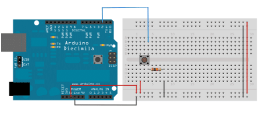
Take 3 pieces of jumper wires and hook them up with your Arduino board.Two of the wires, red and black, goes to the two long vertical rows on the side of the breadboard which become the supply cords of the board in order to carry the required 5V DC to the board.
The third wire is used for connecting the digital pin 2 to one of the leads of the push-to-ON switch.
This particular lead of the button also links up with a pull-down 10k resistor to the negative supply rail or the ground. The other free lead of the switch is linked with the positive of 5 volt supply.
With the above connections made, the switch toggles or performs a dual action in the circuit when given a push.
Normally when the switch is in a disconnected position, its two leads stay isolated, such that the pin which is linked with the ground via the pull-down resistor renders a LOW, or a logic 0 level.
In the pressed situation the switch executes a momentary a bridging of its two leads, such that its leads are subjected to + 5 volts, rendering a HIGH, or logic 1 level across them.
Isolating the digital i/o pinouts from rest of the things, could force the LED to go haywire and cause erratic blinking. This is due to the fact the input being not rendered to anything, or kept in a "hanging" position - meaning it's not designated to any definite logic, neither high nor low ( +5V or 0V), this is reason why we employ the pull-down resistor with the switch.
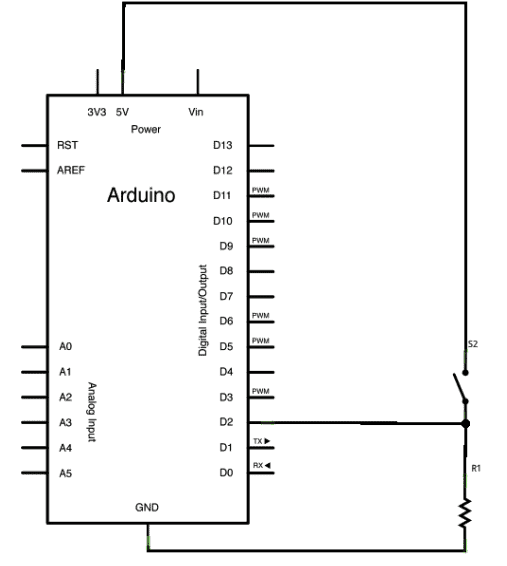
Schematic
Understanding the Code
In the following program below, we commence with serial communication within the setup function at the rate of 9600 bits of data per second, this is initiated between the Arduino board and the attached computer:Serial.begin(9600);
In the next step we trigger digital pin 2, the pin that would be responsible for the output with the push switch as an input:pinMode(2,INPUT);This completes our "setup", now we sail into the main loop of our code.
Here on pressing the pushbutton, 5 volts is allowed to get through our circuit, while the input pin gets linked with the ground through the 10-kilohm resistor when it's in an unpressed condition.
The above is wha we call a digital input, which refers to a condition where the switch can only be in a particular state either an on state (accepted by the Arduino as a "1", or LOGIC HIGH) or an off state (visualized by the Arduino as a "0", or LOGIC LOW), with no other undefined sates in between whatsoever.
The fundamental action that we need to execute in the main loop of the program is to apply a variable for keeping the information in place that's been sent via the push button.
As discussed above with the signals being in the form of either a "1" or a "0", we here employ an int datatype. We can name this variable as sensorValue, and fix it to correspond everything that's being read on digital pin 2. All these become achievable via a one line of code:
int sensorValue = digitalRead(2);Once the Arduino has read the input, print it back to the computer in the form of a decimal value.
This can be implemented with the help of the command Serial.println() in the concluding line of the code:Serial.println(sensorValue);
After this, whenever the Serial Monitor is initiated in the Arduino domain, we would witness a chain of "0"s during the push button is open position, and chains "1"s in cases the button is held in closed condition.
/*
  DigitalReadSerial
 Reads a digital input on pin 2, prints the result to the serial monitor
 This example code is in the public domain.
 */
// digital pin 2 has a pushbutton attached to it. Give it a name:
int pushButton = 2;

// the setup routine runs once when you press reset:
void setup() {
// initialize serial communication at 9600 bits per second:
Serial.begin(9600);
// make the pushbutton's pin an input:
pinMode(pushButton, INPUT);
}
// the loop routine runs over and over again forever:
void loop() {
// read the input pin:
int buttonState = digitalRead(pushButton);
// print out the state of the button:
Serial.println(buttonState);
delay(1);        // delay in between reads for stability
}
Need Help? Please Leave a Comment! We value your input—Kindly keep it relevant to the above topic!