In this article I will show how to construct a digital frequency meter using Arduino whose readings will be showcased on a 16 x 2 LCD display and will have a measuring range from 35 Hz to 1MHz.
Introduction
Being electronics enthusiast, we all would have come across a point where we need to measure frequency in our projects.
At that point we would have realized that an oscilloscope is such a useful tool for measuring frequency. But, we all know that an oscilloscope is an expensive tool not all hobbyists can afford one and oscilloscope might be an overkill tool for beginners.
To overcome the issue of measuring frequency, hobbyist don’t need an expensive oscilloscope, we just need a frequency meter which can measure frequency with reasonable accuracy.
In this article we are going to make a frequency meter, which is simple to construct and beginner friendly, even noob in Arduino can accomplish with ease.
Before going into constructional details, let’s explore what is frequency and how it can be measured.
What is Frequency? (For noobs)
We are familiar with the term frequency, but what really it means?
Well, frequency is defined as number of oscillations or cycles per second. What does this definition mean?
It means the number of times the amplitude of “something” goes up and down in ONE second. For example frequency of AC power at our residence: The amplitude of “voltage” (‘something’ is replaced by ‘voltage’) goes up (+) and down (-) in one second, which is 50 times in most countries.
One cycle or one oscillation comprises of up and down. So one cycle/oscillation is the amplitude goes from zero to positive peak and come back to zero and goes negative peak and return to zero.
“Time period” is also a term used while dealing with frequency. The time period is the time taken to complete “one cycle”. It is also the inverse value of frequency. For example 50 Hz has 20 ms time period.
1/50 = 0.02 second or 20 millisecond
By now you would have some idea about frequency and its related terms.
How frequency is measured?
We know that one cycle is combination of high and low signal. To measure the duration of high and low signals, we use “pulseIn” in arduino. pulseIn(pin, HIGH) measure duration of high signals and pulseIn(pin, LOW) measure duration of low signals. The pulse duration of both is added which give time period of one cycle.
The determined time period is then calculated for one second. This is done by following formula:
Freq = 1000000/time period in microseconds
The time period from arduino is obtained in microseconds. The arduino don’t sample the input frequency for entire second, but it predict the frequency accurately by analysing just one cycle’s time period.
Now you know how the arduino measures and calculates the frequency.
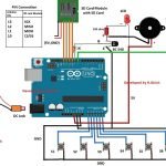
The circuit:
The circuit consists of arduino which is the brain of the project, 16 x 2 LCD display, IC 7404 inverter and one potentiometer for adjusting contrast of LCD display.
The proposed setup can measure ranging from 35Hz to 1 MHz.
Arduino display connection:
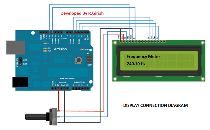
The above diagram is self-explanatory, the wiring connection between arduino and display is standard and we can find similar connections on other arduino and LCD based projects.

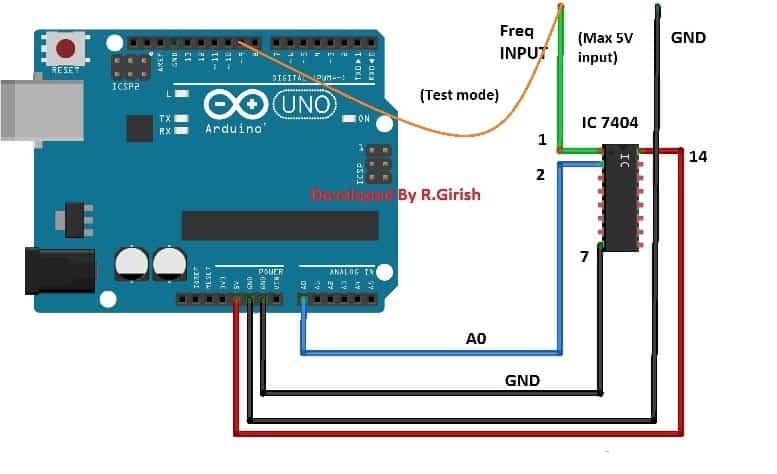
The above diagram consists of inverter IC 7404. The role of IC 7404 is to eliminate noise from the input, so that the noise won’t propagate to arduino which might give false readings and IC 7404 can tolerate short spike voltage which will not pass to arduino pins. IC 7404 only outputs rectangular waves where arduino can measure easily compare to analogue waves.
NOTE: The maximum peak to peak input should not exceed 5V.
Program:
//-----Program Developed by R.Girish (Optimized)-----//
#include <LiquidCrystal.h>
LiquidCrystal lcd(12, 11, 5, 4, 3, 2);
unsigned long X; // pulseIn returns an unsigned long, not a standard int
unsigned long Y;
float Time;
float frequency;
const int input = A0; // Input pin
const int test = 9; // Built-in test PWM signal pin
void setup()
{
pinMode(input, INPUT);
pinMode(test, OUTPUT);
lcd.begin(16, 2);
// Generates a ~490Hz square wave on pin 9 for easy hardware testing
analogWrite(test, 127);
lcd.setCursor(0, 0);
lcd.print("Frequency Meter");
}
void loop()
{
// Read pulse widths in microseconds (with a custom 250ms timeout to keep things fast)
X = pulseIn(input, HIGH, 250000);
Y = pulseIn(input, LOW, 250000);
Time = X + Y;
// 1. Check for 0 FIRST to prevent microcontroller mathematical crash
if (Time == 0)
{
lcd.setCursor(0, 1);
lcd.print("0.00 Hz "); // Extra spaces clear out any old digits
}
else
{
// 2. Use 1000000.0 (float notation) to ensure accurate calculation
frequency = 1000000.0 / Time;
lcd.setCursor(0, 1);
lcd.print(frequency, 2); // Print with 2 clean decimal places
lcd.print(" Hz "); // Spaces clear leftover artifacts
}
delay(500); // Reduce update rate slightly to make it easy on human eyes
}
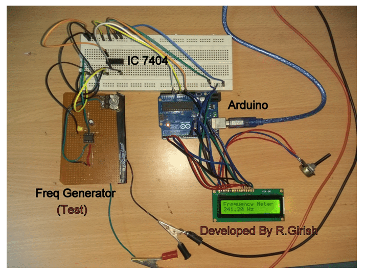
//-----Program Developed by R.Girish-----//Testing the frequency meter:
Once you successfully constructed the project, it is necessary to check whether everything is working fine. We have to use a known frequency to confirm the readings. To accomplish this we are using arduino’s inbuilt PWM functionality which has frequency of 490Hz.
In the program pin #9 is enabled to give 490Hz at 50% duty cycle, the user can grab the input wire of the frequency meter and insert in pin #9 of arduino as shown in figure, we can see 490 Hz on the LCD display (with some tolerance), if the mentioned procedure was successful, you frequency meter is ready to serve you experiments.
Author’s prototype:
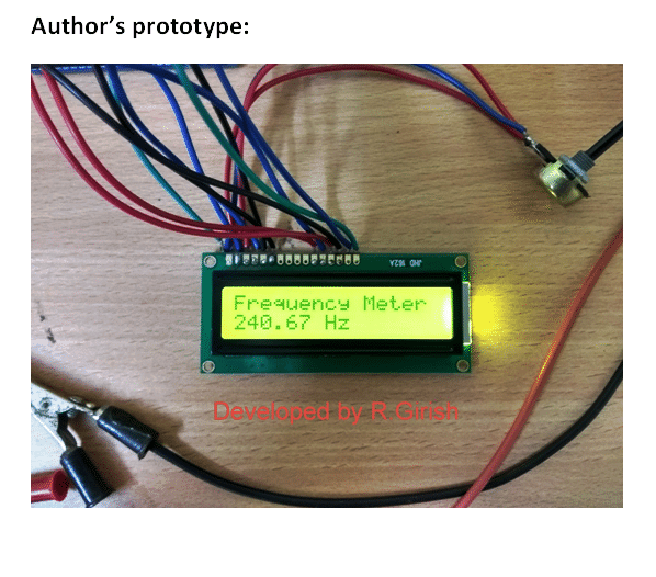
The user may also test this Arduino frequency meter circuit prototype by using external frequency generator which is shown in above image.


Questions & Answers
can we cheq motherboard 32mhz crystal frequency with this curcuit
Hi Rajesh,
If you are connecting the crystal terminals directly to the input of frequency counter, then NO.
Also this frequency counter can only read under 1 MHz, that’s my assumption.
Regards
* not just assumption but, the maximum limit of the circuit.
Mr. GR will answer your question soon….