In this post I have explained a buzzer circuit with an incrementing beeping rate, which can be used in critical warning signalling applications. The idea was requested by Mr. Lee.
Buzzer with Progressive Beep Rate
- Could you help me with a circuit. I've been trying to find but so far had no luck! I need a pulsing piezo that will start with a short blip and then over a period of may be 2 minutes, progressively increase the frequency of blips to maybe then permanently on or just rapid blips, similar to a game type of timer where the blips get quicker as the seconds pass.
- I want to use it on a car(so 12volt) to indicate when an anti car jack type immobilizer is about to operate. I've got ideas for the main immobilser circuitry but i'm struggling with the rising pulse rate buzzer/piezo.
- To simplify it slightly i would just use a 12v piezo driven by the rising pulse circuit.from when power is connected the timing cycle can start and maybe a variable resistor to tweak the pulsing cycle?
- Any ideas would really really be appreciated-if you can help,
The Design
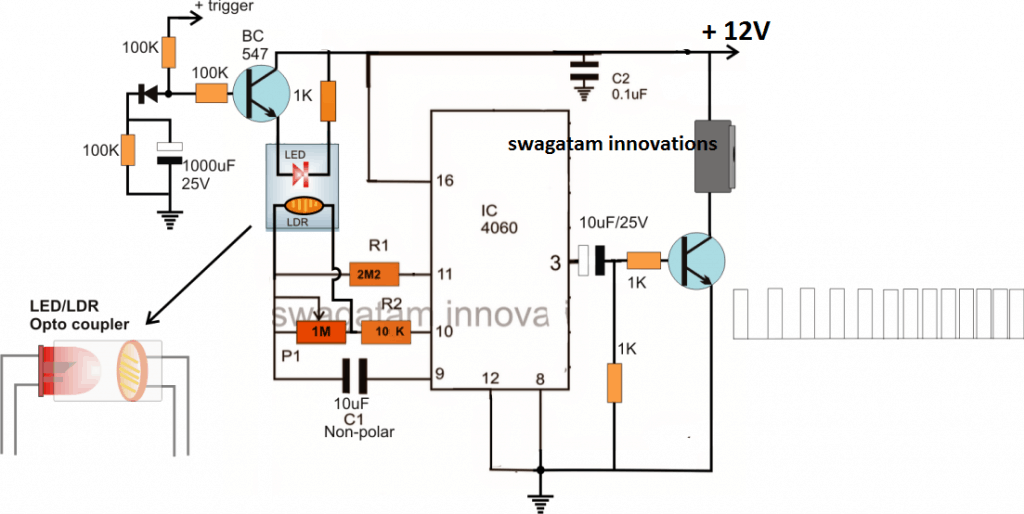
The requested design for a buzzer circuit with progressive or an incrementing beep rate can be basically implemented through a voltage to frequency converter circuit
Although you may find many variants of voltage to frequency converter circuits, these may not be entirely easy to build due to their fairly complex design or due to the inclusion of unpopular, obsolete IC in it.
An alternative easier way of achieving this function could be by modifying an existing IC 4060 astable circuit with a homemade LED/LDR optocoupler as shown above.
As can be seen in the diagram, the LED/LDR opto is triggered through a slow rising voltage across its LED leads, which in turn induces a correspondingly slow decreasing resistance on the attached LDR.
The slow decreasing resistance of the LDR causes the timing capacitor of the astable to charge at proportionately faster rate, which subsequently causes a proportionately progressing or augmenting frequency rate at the output of the IC 4060.
P1 is for fine tuning the timing delay between the progressive beeps, possibly this component could be completely eliminated.
C1 can be also tweaked for adjusting the delay period between the beeps in order to make them faster or slower as per the application requirement.
The indicated buzzer unit here may be procured readymade in the form of a piezo buzzer or this can be also built at home by following this simple buzzer circuit guide.
Update:
Another interesting way of implementing a progressive buzzer beeper circuit could be by using a IC 555 monostable circuit and apply a slow rising voltage at its pin#5 control input....will update the circuit soon here.



Questions & Answers
It is attached.
Norman, It is attached, but can you see the details of the image? The image quality is very bad and the parts and their values cannot be identified.
Even the one you sent in my email was very small and part specs unidentifiable.
I think you should scan a clearer image and upload it again, so that we can identify the details correctly and then discuss it further.
The picture is a microsoft word document. That is the way I am able to copy it from my design software.I will try taking a picture of the printed page and then try again.
You must first save the image separately as .png or .jpg file on your PC desktop, only then it can be uploaded to any site online.
I don’t see the image under my comment. When I open it from my computer, a red box appears in the upper right of the screen, but it doesn’t stay there long enough for me to read what it says. The red box says “not allowed file type”
You should first save the image on your PC desktop as a standard .png or .jpg image and then upload this image to this website comments.
The image must be clearly visible under your comment, once it is uploaded and attached.
Currently I cannot any image uploaded to this site by you, that means the image upload is not happening correctly.
Ok, I think I got it attached.
I am afraid it is not attached still. In my media folder I can only see one amazon QR code image uploaded today, not sure by whom?
Once you upload it, you should be able to see it under your comment…
Hi Swagatam,
The attached circuit is supposed to work as follows: When 12v is applied, the 555 is triggered and powers the rest of the circuit for a specific time frame. I have incorporated your incrementing beeper circuit to begin beeping and getting faster as time goes on. The beeper is tied to pin 7 of the cd4060. Pin three will eventually be triggered if the 12v supply is continued. The 12v supply is provided by a PIR circuit which will time out if not retriggered by movement in the area. If the PIR is retriggered enough, the pin 3 of the cd4060 will trigger a bc337 which will trigger a bc327 to power the siren. The siren will wail until there is no movement and the PIR circuit times out. The incrementing buzzer is meant to alert the intruder to leave the area. If they don’t leave, then the siren will wail to encourage them to leave.
Hi Norman,
It seems you forgot to attach the image, please upload it again, I will try to figure it out!
Hi Swagatam,
Can a standard opto-coupler be substituted for the LDR/ Led opto-coupler? If so, what other changes should be made to the circuit?
Hi Norman,
The LDR is required for generating the incrementing pulse frequency at the output of the IC. A standard opto won’t do this.
Hi Swagatam Majumdar,
I would like to make a continuity tester with the 5 v buzzer. But the problem is the buzzer will beep even if the cable has some resistance. I checked some articles and found normal multimeters beep till 40ohms in the continuity mode. So is it possible to make a simple circuit for the continuity tester? I would like to have them small for better handling.
If the resistance is 0-40ohms it should beep continuously above 40ohms with no beep or a step-by-step beeping line 0-40 continuous beep and 40to 100ohm double beep, 100t0500 triple beep above that no response. Like this…
Am working in the automobile field and it’s not convenient to use multimeter all the time so a small testing prob-like item will be more helpful.
Actually, I made a dc voltage tester with dc led voltmeter as a replacement for the test lamp and I would like to add the continuity tester as well.
Waiting for your response and thank you.
Hi Anuraj, getting beeps at different rates can be difficult to achieve. However, to get the beeping after a certain ohm range may be possible. The op amp circuits presented in the following article might be helpful to get the intended results. You can check them out.
https://www.homemade-circuits.com/make-this-simplest-continuity-tester/
Interesting.
I have a set top box which has a 5mm signal led that lights up when I connect the dish cable into the set top box.
I was looking to add a buzzer to this. So I desoldered the led and soldered a self driving piezo buzzer to it. I found that it barely made a sound. It buzzes when I put a 9v battery to it. I took out my tiny oscilloscope and measured across the led. It was 120hz. 2.2vpp. 25-45% duty cycle.
I then connected a 817 optocuplar on the led terminals. The conductive terminals go to an enternal 12v supply and the buzzer in series.
Now the buzzer makes sound when I connect dish cable to set top box but the sound is very strange. It sounds like 60hz sound we hear under the electricity transformers. Why doesn’t it make TUUUUUuu sound? Is it because of the duty cycle?
I don’t understand. Can you help please.
If you are seeing 120 Hz across the LED, then the opto coupler and the buzzer would also oscillate at 120 Hz
Thanks! This makes complete sense. My knowledge has increased.
No problem!
Hi Swagatam,
I have another question. What does the 10uF capacitor connected between pin 3 and the transistor do?
Hi Norman, the 10uF ensures that the pulses to the buzzer are short, so that the progressive beeping is clearly audible.
Hi Swagatam,
I have a question about the above circuit “Buzzer with Progressive Beep Rate”. I would like to use a 555 timer as the trigger and once the max rate is achieved, the circuit would reset and wait for the next trigger. I would probably use a PIR to initiate the 555. The 555 would run through several cycles until the PIR output timed out. I would be driving a LM3915 and LEDs with the “Buzzer with Progressive Beep Rate ” circuit instead of a beeper. I have built the “Buzzer with Progressive Beep Rate” circuit and it works very well, so I thought I might be able to adapt it to the new scenario. I just don’t know how to reset the “Buzzer with Progressive Beep Rate” circuit after it reaches a max rate.
Hi Norman, you can probably use two LDRs in the LDR/LED box. The second LED could be used to detect the maximum threshold, and an attached op amp comparator could be used to reset the IC.
Hi Swagatam,
I am trying to build a beeper circuit that will beep once and then beep 5min later, then beep 10 minutes later, then beep 7 min later. The times are not really that important, but I want them to vary. I don’t want to learn programing for micro controllers, so is there a way to do this with 555 timers and or shift registers or other ic’s? Thanks!
Hi Norman, you can probably try using the sequential timer concept presented in the following article. You can replace the LED with a beeper buzzer, and alter the R2/C2 individually to get different time delays at the respective sequences.
https://www.homemade-circuits.com/cube-light-circuits/
you can replace the BC547 with a MOSFET in order to enable extremely large values of R2 and bigger delays of above 5 minutes.
Hi Swagatam, I have tested what you told me for the “Buzzer with increased beep frequency” circuit by connecting a 100uF / 25V capacitor between pin # 5 and ground on the 555 but the frequency does not change..I just get a constant tone. Would you be so kind as to provide me with an electrical diagram?
Hi Nandu, you can replace the buzzer with an LED and check its blinking rate. You can try manually shorting the pin5 to ground and then remove the shorting, check the LED response in both the conditions, this will prove whether the pin5 response is effecting the output PWM or not. What the pin5 capacitor does is, short the pin5 to ground initially which reduces the pin3 output PWM, and as the capacitor charges, the PWM slowly broadens and gets wider and wider.
Thank you very much Swagatam..you are very kind to answer me … I understand that then we can dispense with the led-LDR optocoupler stage and the transistors, connected in normal astable configuration? Excuse me, my knowledge of electronics is basic .. I thought you had assembled and checked the circuit, that’s why I asked you .. Thank you very much.
You are welcome Nandu, yes you can use the LED/LDR concept with a transistorized astable circuit, or any other astable circuit.
Good afternoon Mr. Swagatam commented that you would upgrade the progressive buzzer circuit using a 555 monostable IC circuit. Have you done it yet? I have not been able to locate it among your projects .. I would be very interested in getting it .. Thank you very much
Hello Nandu, the IC 555 can be configured in the normal astable mode, and a buzzer connected across its pin#3 and ground. This will produce an intermittent beeping sound at a constant rate. However, if a 100uF/25V is connected between the pin#5 and ground, it will create a slow intermittent intervals when power is switched ON, and this intermittent rate will get faster and broader as the 100uF charges up. This is according to my assumptions
Hi Swagatam,
I was trying to use your “Buzzer with incrementing beep rate” circuit and I had problems with the CD4060. I tried several things, but was unable to make it oscillate(maybe it was oscillating too fast). I guess that would work correctly if pin 3 oscillates at a progressive rate. I just could not get it to work. I didn’t have a 10uF non polarized cap so I used two 10uF electrolytic back to back. It didn’t work, so I put seven 1uF ceramic caps in parallel, but it didn’t work. I noticed you suggested a 555 timer would work to do the same thing using a variable input to pin 5. I bread boarded it and decided to try varying the resistance between pin 6 and pin 7. It works great. I used a variable pot from pin 6 to the LDR and from the LDR to pin 7.
Hi Norman, a 4060 IC oscillator is very basic and straightforward design, if it didn’t work for you then there should be something not correct in your circuit connections or the IC may be duplicate. You should have first tried to build the basic oscillator design, then tried to move the pot up down manually to check if the the output varied progressively.
Hi Swagatam,
In the above circuit, you used a BC547 (NPN) transistor to power the LED optocoupler. What determines when you can use a NPN transistor to provide power and when you have to use a NPN/PNP combo pair to power a circuit?
Hi Norman, I have used NPN because the switching input is positive, so PNP won’t work, and the common-emitter mode of the BJT ensures that the emitter voltage varies in accordance with the rising falling waveform, producing an equivalent rising and falling illumination on the opto LED
Hi Swagatam,
I was looking at the above circuit and have a question. How does the LED in the LED/LDR opto coupler light when both sides of the LED are connected to the positive rail? Also would this circuit work with progressively driving a LED instead of driving a piezo?
Thank you Norman, it seems to be a drawing mistake, but never mind, I have added a correction message just under the image so that the viewers can take note of that.
olto interessante
Thank you!!