In this post I have explained a 555 based PWM circuit which can be implemented as a 150 nos or more LED light intensity controller circuit. The idea was requested by Mr. Anil
The Circuit Request
I want use 12V/5A DC supply
Thanks & early reply is highly appreciated.
Thanks & regards
Anil Rustagi
The Design
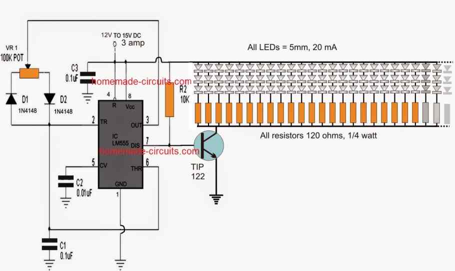
The figure shows a PWM based LED intensity controller circuit using the IC 555.
IC 555 are popularly used in most PWM based circuit applications due to their easy configuration and precise PWM generation ability which is adjustable right from minimum to the maximum.
In the shown design the 555 IC is configured in its standard PWM mode with a slight variation wherein it's discharge pin7 is used as the output instead of its usual pin3 which is rather employed for the discharge function here.
The above configuration makes the functioning a bit more efficient and allows the spaces of the duty cycles to be sharp and more accurate.
Pin7 becomes responsible for creating negative pulses only for the attached transistor, while the positive pulses are derived from the 10 k resistor across the base and positive of the transistor.
VR1 is used as the PWM control pot which almost provides a range from zero to the maximum supply voltage for the LEDs through varying ON/OFF duty cycles as determined by the setting of the 100k pot
TIP122 is rated to hold upto 5 amp with adequate heatsinking meaning more than 150 LEDs rated at 20 mA each can be included with the device as shown in the circuit diagram.



Questions & Answers
I made that circuit it works really fine. Thanks for your website.
Thank you, I am glad it worked.
Hi Sir, I Want New Design for 3 10 V LED Bulb Run in 24 Hours, Like 12v – 12ah Battery, Fast Charge Battery, Inverter Must-Have USB Mobile Charger 3 amp, And Three Port For LED Please Design This Project
Mr. Majumdar,
I would like to drive directly a serious of 72 no SMD 5730 ( LED),12 V DC , ( Specification written on the Strip 990 x 12*1.0-5730). Kindly let me know a suitable circuit diagram at your earliest convience.
Regards,
DK Ghosh
Kolkata
09748747010
Hello Mr. Ghosh, since the LED strip is not heatsink based, it may not require a current controlled circuit. You can try any standard 12V 1 amp adapter to power the strip, provided the total consumption of the strip is below 1 amp
Mr. Swagatham,
Thank you so much for this circuit, it works great.
It’s my pleasure Jaimitove, I’m glad it worked for you!!
Regarding my 1st question from my last post about using multiple TIP 122 in parallel feeded with same PWM,kinda like this one: https://skaled.files.wordpress.com/2013/05/image10.png but mosfets with TIP 122.
yes that's possible, your diagram is correct and can be used in the application….
Hi again!Just wondering if multiple TIP 122s can be used in parallel using the same pwm output from the 555 ckt from above to enable higher amps loads.
Also if above ckt can be made using mosfet with an NPN (before mosfet)to amplify PWM signal in order to handle higher currents.
Nevermind with my last question,I thought there was some voltage drop across the ckt :P.
Will try the circuit with higher amps using darlington pair(of 2n2222 and 2n3055) u suggested some time before.
Also m confused,should I directly feed pwm to 2n2222 or should i use a resistor bw pwm o/p and 2n2222 base.Also Where should R2 be connected across then(before or after the base resistor).
Really appreciate your work bro,Keep it up 🙂
any NPN power transistor will work in the shown configuration…
Will be making high amp ver. of the same ckt.Would TIP 2055 work instead of 2n3055?
i appreciate your involvement too..keep up the good work!!
OK no issues.
You will definitely require a resistor at the base of the 2N2222, it could be anything between 1K and 10K.
Tried reducing C1 at 0.1uf to 0.01 and voila it worked :).Also I kept C2 as 0.001.Does C2's value matter?
Also is there any way to reduce voltage drop before led bank section?
It was not a typo,…C1 is responsible for the frequency rate not C2…therefore C1 needed the modification.
reducing C2 will increase the stray signal pickup from atmosphere so it's better to increase its value instead of reducing.
sorry i could not understand your second question
"Also is there any way to reduce voltage drop before led bank section?"
I replaced the c2 cap which was .01uf not c1(i thought that was a typo).Should I decrease c1?
Hi,
Made the above ckt today and tried driving 5x 5W leds(of 9-12v) with it.The circuit is working but there is continuous flickering associated with it.Only at 100% brightness there's no flicker.I tried once with 12v,2A SMPS and next time with PC SMPS(modified).Please tell me what should be the problem and how to tackle it.
(Will post a link of the video of the driver in action)
Tried today,replaced .01uf to .001uf.The flickering have reduced but still noticeable.Should I further decrease capacitance?
I saw the video, it's probably due to low frequency from the 555 output, decreasing C1 value will increase the output frequency and hopefully correct the issue….
Try reducing C1 value to 10nF or 1nF, and check the difference.
Dear Sir,
I'm Dhammika from Sri Lanka. How can modify this circuit to flash 150 LEDs with flashing time adjustable. Thank you for your work.
blinking can be altered by altering the frequency rate through the previously suggested pot arrangement
Thank you. But actually I mean to blinking these 150 LEDs with facility to change the blinking speed.
Dhammika, you can add another in series with pin#3 and VR1 center arm..and adjust this pot for getting the adjustable eature
Hii Sir.i want 20watts led driver circuite.plz help me.
thanks
Hello Swagatam I need to build a LED grow light , can you help me with the power supply straight from the main?
the ratio of the LED are 4:1 , 4 red one blue , the res are 2.2 volt and the blue are 3.3, all 3 watt led..
thank you in advance for your help..
regard walter
Hello Walter,
you can make three strings, in the following manner:
2 strings of red LED, each consisting of two red LEDs in each series and a 1.5 ohm 1 watt resistor on each series.
a third string consisting of a single blue LED with a 3 ohm 1 watt resistor.
put all these strings in parallel and power it using your smart phone charger.
or alternatively you can connect all the 5 LEDs in a single series with a 3 ohms resistor (1 watt) and power it using a 12V 1amp adapter
Hi, Swagatam sir.
Thank u so much for this blog. I made ur 1W mains led circuit. It's working very well.
Can u provide me circuit for 240V drived 120 nos led (5mm straw hat). It must be reliable surge protective coz our supply fluctuates many times.
I want to use it to lit my porch.
Thank u sir.
Thank you Lord of Blackspot,
you can try the following design for your need:
https://www.homemade-circuits.com/2014/04/simplest-100-watt-led-bulb-circuit.html
if you are using 5mm, 20mA LEDs then make sure to reduce the input capacitor value to 0.47uF/400V
all the best to you!
Mr.Swagatham,
The second transformer is for driving voltmeter circuit , though i queried with particular requirement in mind but pls consider it as general question as it might benefit me as well as others who might face the need to use more than one transformer so tips regarding safe installation of them would be valuable.
Mr. Gururaj, you can use a 7812 IC or IC 7805 as per the voltage rating of the voltmeter circuit and power it from the same transformer which is being used for the LM317
Hello Mr.Swagatham,
Thanks for that tip about transformer i will keep that in mind but may i know the reason why did you mention 32v restriction.
I want to install other transformer for voltmeteri would keeping two transformer like inch apart deteriorate its performance ?
Hello Gururaj, the maximum tolerable voltage of LM317 is 35V that's why I cautioned to keep it below 32V.
why two transformers?? you can make it using a single center tap transformer.
Sir, you are doing a great job with this blog.
Will you help me? I ve parts of an emergency lamp that became useless due to battery failure. It is China made 31 LED folding type table lamp using 4.5v battery. You might have seen it. Its battery is not available in local market. I made an outline of its circuit. (It is actually modified version of your blog https://www.homemade-circuits.com/2012/04/how-to-make-led-bulb-circuit.html .) Can you redesign the circuit by replacing 4.5 volt battery with 6v 4.5ah battery ? It would be great if you added an overcharging indicator too. How can i mail you diagram of the circuit ?
Alchemist, just add three 1N4007 diodes in series with the positive of the 6V battery and it will become compatible with the existing 4.5V circuit.
If possible I'll try to update a transistorized high low battery indicator in this blog soon.
Hello Mr.Swagatham,
Based on your suggestion i have drawn a rough schematic pls kindly have a look at it and let me know if i got it right.
picpaste.com/revisedschematic-NM4dvWwT.png
the transformer should be preferably rated at 12-0-12v, so that the total voltage across the LM317 circuit never exceeds 32V
Hello Gururaj,
Yes that's correct…..use a SPDT toggle switch for better reliability.
Thank you very much
Hello Mr.Swagatham,
Thanks for your prompt reply, the solution suggested is helpful but it deals with output stage.Whereas what i wanted to do was activate or deactivate LM337 circuit by cutting off power supply to it from transformer as i wont be using negative voltage as often as positive voltage i think that would lead to power efficiency and better temperature control , my psu is going to have three terminals for (+),gnd,(-) lines so please help me in this regard.I also think that merely incorporating switch in transformer line to circuit wont help much as there could be a spillover effect from positive voltage circuit to negative voltage circuit.So please help me with your resourceful knowledge.
Hi Gururaj, the above explained solution will work, other more effective and complex ways could be figured out but may not be necessary with the above simple solution in hand….
Hello sir…
I hv question .. In a curcuit, can i use DIODE IN4007 in the place of IN4001 . both r same?
And Can i use capacitor 0.01i or 0.22u in the place of 0.04u
Because these items is not available in market.
1N4001 will block not more than 50V while 1N4007 is rated for upto 1000V…if your circuit is well below the 50V mark then any of the two can be used..