A neon lamp is a glow lamp made up of a glass cover, fixed with a pair of segregated electrodes and containing an inert gas (neon or argon). The main application of a neon lamp is in the form of indicator lamps or pilot lamps.
When supplied with a low voltage, the resistance between the electrodes is so large that the neon practically behaves like a an open circuit.
However, when the voltage is increased gradually, at a certain specific level where the inert gas inside the neon glass begins ionizing and results in being extremely conductive.
Due to this the gas starts producing a radiant illumination from around the negative electrode.

In case the inert gas happens to be neon, the illumination is orange in color. For Argon gas which is not very common, the emitted light is blue.
How Neon Lamp Works
The working characteristic of a neon lamp can be witnessed in Fig. 10-1.
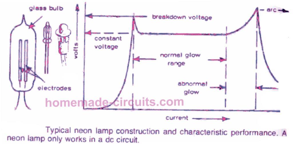
The voltage level which triggers the glowing effect in the neon bulb is termed as the initial breakdown voltage.
As soon as this breakdown level is struck, the bulb is triggered into "firing" (glowing) mode, and the voltage drop across the neon terminals stays practically fixed irrespective of any kind of increase in current in the circuit.
In addition, the glowing section inside the bulb increases as the supply current is increased, until a point in which the total area of the negative electrode is filled by the glow.
Any additional escalation in current may then drive the neon into an arcing situation, in which the glow illumination turns into a blue-white colored light over the negative electrode and begins producing rapid degradation of the lamp.
Hence, for you to illuminate a neon lamp efficiently, you must have sufficient voltage for the lamp to "fire," and, and then, ample series resistance in the circuit to be able to restrict the current to a level that will guarantee that the lamp stays running within the typical glowing section.
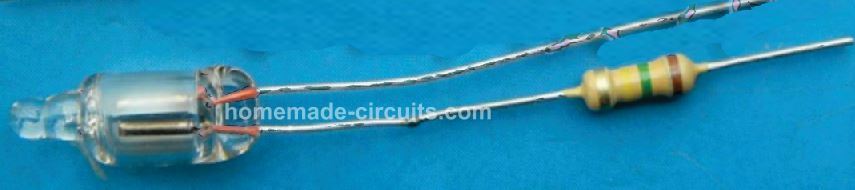
Since the neon resistance by itself is extremely small soon after it is fired, it needs a series resistor wit one of it supply lines, called a ballast resistor.
Neon Breakdown Voltage
Commonly the firing, or breakdown, voltage of a neon lamp could be anywhere between approximately 60 to 100 volts (or occasionally even greater). The continuous current rating is fairly minimal, generally between 0.1 and 10 milliamps.
The series resistor value is determined in accordance with the input supply voltage across which the neon may be attached to.
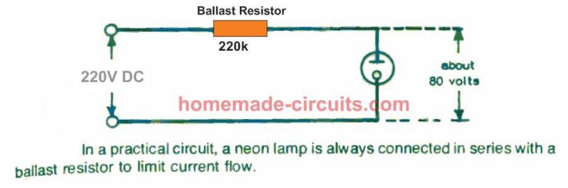
When it comes to neon lamps being controlled with a 220 volt (mains) supply, a 220 k resistor is usually a good value.
With regards to many commercial neon bulbs, the resistor could possibly be included in the body of the construction.
Without any precise info given, it may be supposed that a neon lamp may have simply no resistance while it is illuminated, but may have a drop of around 80 volts across its terminals.
How to Calculate Neon Resistor
A proper value for the neon ballast resistor could be determined by taking this benchmark into account, which is relevant to the precise supply voltage utilized across it, and presuming a "safe" current of, approximately 0.2 milliamps, as an example.
For 220 volt supply, resistor may have to lose 250 - 80 = 170 volts. Current through series resistor and neon bulb will be 0.2 mA. Therefore we can use the following Ohm's law formula for calculating the appropriate series resistor for the neon:
R = V/I = 170 / 0.0002 = 850,000 ohms or 850 k
This resistor value would be safe with the majority of commercial neon lamps. When the neon glow is not quite dazzling, the ballast resistor value could be reduced to drive the lamp higher across the typical glow range.
That said, the resistance must in no way be lowered too much which may cause the whole negative electrode to be engulfed by the hot glow, because this may indicate that the lamp is now inundated and getting close to the arcing mode.
One more issue regarding the power of the neon glow is that it may typically look a lot shiny in ambient light compared to in darkness.
Actually, in total darkness the illumination could be inconsistent and/or call for an increased breakdown voltage to initiate the lamp.
Some neons possess a tiny hint of radioactive gas mixed with the inert gas to promote ionization, in that case this kind of effect may not be visible.
WARNING: ALL THE CIRCUITS EXPLAINED BELOW INVOLVE MAINS AC POTENTIALS AND ARE THEREFORE EXTREMELY DANGEROUS TO TOUCH IN POWERED AND UNCOVERED CONDITION. USERS ARE RECOMMENDED TO EXERCISE EXTREME CAUTION WHILE HANDLING THESE CIRCUITS.
Simple Neon Bulb Circuits
In the above discussion we have elaborately understood the working and characteristic of this lamp. Now we will have some fun with these devices and learn how to build some simple neon lamp circuits for using in various decorative light effect applications.
Neon Lamp as a Constant Voltage Source
Due to the neon lamp's constant voltage features under standard light conditions, it could be applied as a voltage stabilizing unit.
Therefore, in the circuit displayed above, the output extracted from each side of the lamp might work like an origin of constant voltage, provided that the neon continues to work within the typical glowing region.
This voltage would be then identical to the minimal breakdown voltage of the lamp.
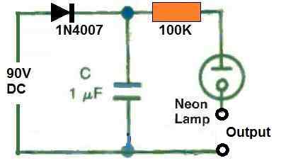
Neon Lamp Flasher Circuit
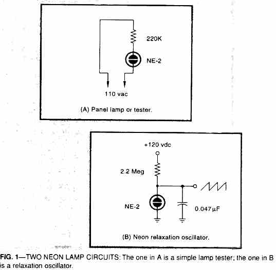
Using a neon lamp like a light flasher in a relaxation oscillator circuit can be seen in the image below.
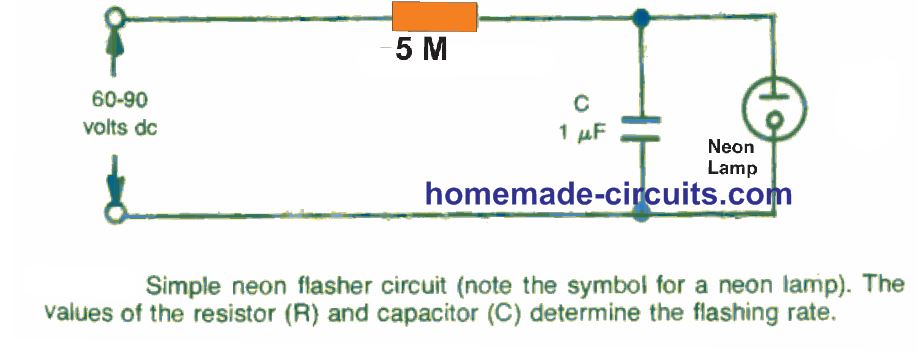
This includes a resistor (R) and capacitor (C) attached in series to a supply voltage of a dc voltage. A neon lamp is attached in parallel with the capacitor. This neon is applied as a visual indicator to show the functioning of the circuit.
The lamp almost performs like an open circuit until its firing voltage is reached, when it instantly switches current through it quite like a low value resistor and begins glowing.
The voltage supply for this current source therefore needs to be higher than that of the neon's breakdown voltage.
When this circuit is powered, the capacitor begins accumulating a charge with a rate determined by the resistor/capacitor RC time constant. The neon bulb gets a voltage supply equivalent to the charge developed across the capacitor terminals.
As soon as this voltage reaches the breakdown voltage of the lamp, it switches on and forces the capacitor to discharge via the gas inside the neon bulb, resulting in the neon to glow.
When the capacitor discharges fully, it inhibits any further current to pass through the lamp and thus it shuts down again until the capacitor has gathered another level charge equal to the firing voltage of the neon, and the cycle now keeps repeating.
Put simply, the neon lamp now keeps flashing or blinking at a frequency as decided by the values of the time constant components R and C.
Relaxation Oscillator
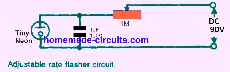
A modification in this design is indicated in the above diagram, by using a 1 megohm potentiometer working like a ballast resistor and a couple of 45 volt or four 22.5 volt dry batteries as the voltage input source.
The potentiometer is fine-tuned until the lamp illuminates. The pot is then rotated in the opposite direction until the neon glow merely fades out.
Allowing the potentiometer to be in this position, the neon must then begin blinking at different flashing rates as determined by the value of the selected capacitor.
Considering the values of the R and C in the diagram, the time constant for the circuit may be evaluated as follows:
T = 5 (megohms) x 0.1 (microfarads) = 0.5 seconds.
This is not specifically the true flashing rate of the neon lamp. It might require a period of several time constant (or fewer) for the capacitor voltage to accumulate upto the neon firing voltage.
This may be higher in case the turn-on voltage is over 63 % of the supply voltage; and may be smaller if the neon firing voltage spec is lower than 63 % of the supply voltage.
Additionally, it signifies that the blinking rate could be modified by changing the R or C component values, possibly by replacing various values worked out to provide an alternative time constant; or using a parallel attached resistor or capacitor.
Hooking up an identical resistor parallel with R, for instance, would likely make the flashing rate two times more (since adding similar resistors in parallel causes the total resistance to be reduced to half).
Attaching an identical value capacitor in parallel with the existing C would likely cause the flashing rate to become 50% slower. This type of circuit is referred to as a relaxation oscillator.
Random Multiple Neon Flasher
Replacing R with a variable resistor could enable adjustment for any specific desired flashing rate. This could also be further enhanced like a novelty light system by attaching an array of capacitor neon circuits, each having its own neon lamp in cascade as shown below.
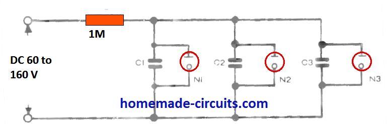
Each of these RC network will enable a unique time constant. This may generate a random flashing of the neon across the entire circuit.
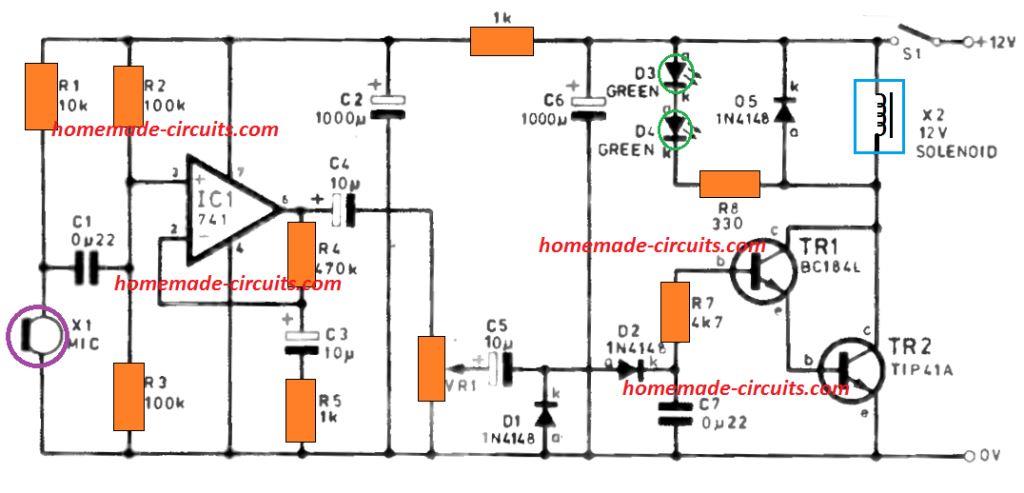
Neon Lamp Tone Generator
Another variation of a neon lamp application as an oscillator could be a relaxation oscillator circuit is shown in the figure below.
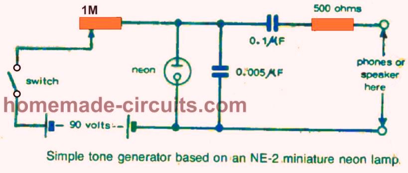
This can be a genuine signal generator circuit, whose output could be listened through headphones or perhaps a small loudspeaker, by suitably adjusting the variable tone potentiometer.
Neon flashers could be designed to function with random manner or sequentially. A sequential flasher circuit is displayed in Fig. 10-6.
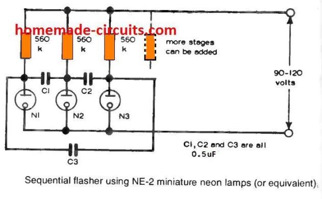
Additional stages could be included in this circuit, if required, by using the C3 connection to the very last stage.
Astable Neon Lamp Flasher
Lastly, an astable multivibrator circuit is revealed in the figure below, employing a pair of neon lamps.
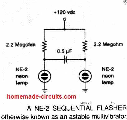
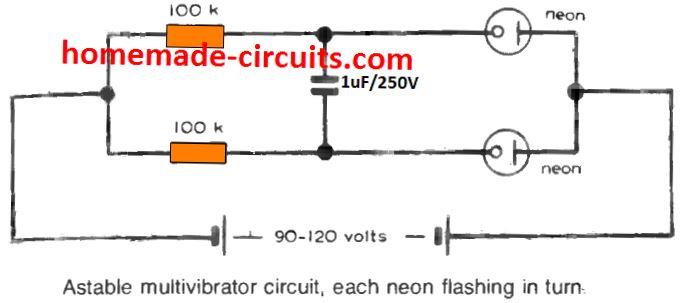
These neons will blink or flash on/off in sequence at a frequency decided by R1 and R2 (whose values must be identical) and C1.
As a basic instructions on flasher timing, increasing the ballast resistor value or the capacitor value in the relaxation oscillator circuit can reduce the flashing rate or the flashing frequency; and vice versa.
However, in order to protect the working life of a typical neon lamp, the ballast resistor value utilized must not be lower than approximately 100 k; and finest results in very simple relaxation oscillator circuits may often be accomplished by maintaining the capacitor value under 1 microfarad.
More Assorted Neon Circuits
Neon Twinkling Star
The next neon lamp circuit provides a lovely neon glitter shine light outcome. In the past, I employed this design oftentimes for party decorations. Because of the dissimilarities in lamp firing limits, the illumination sequence results in essentially random therefore twinkling lights or "tiny blinking stars."
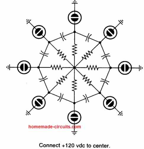
At any moment, a single (or sometimes a couple of) lamps tend to be illuminated allowing the capacitors their charging routes. When the capacitors charge, this exceeds the firing threshold for another neon, forcing it trigger ON. Due to a commutation impact, some lamp in the lit up mode subsequently turn off some other lamp which are previously lit up. These RC and neon networks are basically relaxation oscillators.
For these oscillators to work, the resistors and supply voltage all need to be selected to sit around the negative resistance portion of the NE-2 neon curve. This often takes place within a somewhat large value range. Some further experimentation might be required for something additionally extravagant.
Resistors having the value in the range of one to four megohm can be generally a good place to start. Precisely what is amazing is the fact that I still have no idea how to implement this kind of illumination pattern using LEDs which could turn out to be distantly as easy, as inexpensive, or as low in energy consumption.
Neon Lamp Driver Circuit
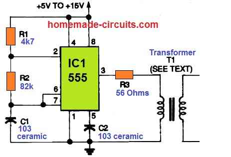
With a 5- to 15-volt DC supply, the circuit above may be used either to drive a neon light or for generating a low-current DC voltage of up to many hundred volts. The 555 is set up as a 3-kHz astable multivibrator, with its square-wave output supplied to the primary winding of the indicated transformer T1, via the resistor R3.
Transformer Details
T1 in this circuit can be a tiny audio transformer with appropriate turns ratio required to produce the necessary high output voltage. A 10 volt input supply and a transformer having a 1:20 turns ratio will provide an unloaded DC output of 200 volts peak in this circuit. With the help of a half-wave rectifier and a filter capacitor, this AC power may be readily converted to DC.
6 V Neon Flasher Circuit
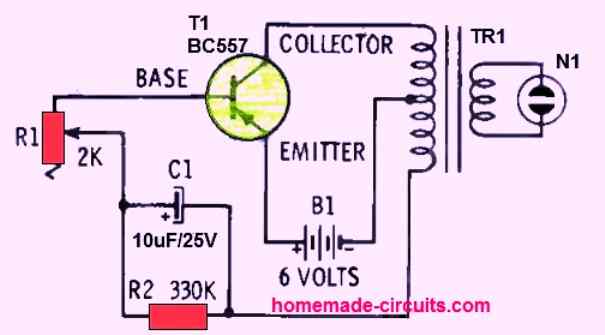
We've all seen those fascinating flashing neon signs, but getting the right voltage to "trigger" the bulb into light has proved to be a major challenge for do-it-yourself projects. You can make the neon N1 not only light up but also flash erratically using the unique arrangement illustrated in the above schematic, all while using a single 6 volt battery.
The main component of the circuit is, of course the transformer TR1. TR1 can be a 0-6V to 220V step-down transformer, which steps-up the six volts to 220 V in order to power the neon bulb.
This transformer does not need to be a specific type; it can be almost any available general type.
The setting of potentiometer R1 greatly affects how quickly the neon light flashes. You'll notice that there is no power switch in this circuit; this neon flasher circuit uses so little current that it can run on only four size -D flashlight batteries for virtually a lifetime.


Questions & Answers
I seem to recall that a relaxation oscillator can also be made by connecting the resistor, the capacitor and the neon globe all in series. I remember when I was at school 65 years ago working out the waveforms of the two configurations. They were both sawtooth waves but in one the teeth pointed forwards while with the other the teeth pointed backwards.
Thanks for your kind feedback and your valuable insights, I truly appreciate it…hope the readers will find it helpful…
A hidden, small 8 ohm speaker in series with a slow-flashing neon light creates the illusion that you can hear the flash.
Excellent Page and Explanations of Neons. Sadly on the page below Non of the pictures are showing..?
https://www.homemade-circuits.com/neon-lamps-working-and-application-circuits/
I tried 3 different web browsers – same result. Any chance the pictures and diagrams can be re-linked to the webpage..?
Thank you Swagatam. It looks like all the pictures on your website are back where they belong. I was looking through your pages because I wanted to build a reliable circuit to create a flashing Neon bulb using 220V supply. You have an example of a flashing neon on your web page; https://www.homemade-circuits.com/neon-lamps-working-and-application-circuits/ but it is showing as power by 90V. Is there a different circuit diagram for 220V supply or can I just use the 90V diagram..?
Thanks Andy for updating the info, I am so relieved to see my site restored again correctly.
Regarding the 90V issue, I think the 90V can be replaced with 220V and the parallel capacitor value tweaked appropriately for getting the proper flashing effect on the neon. Any resistor between 1M and 3M can be tried.
Please try that and let me know how it goes…
Hey, thanks so much for notifying the issue, yes my site was hacked but fortunately now it has been restored back…
Please check it now, I think the images are back now…
hi Swagatam
Ihave a CRT Hung Chang oscilloscope with a CRT with lights at bottm of tube but no beam.have noticed neon lamps on cct board glowing and arcing was wondering what purpose they serve .and could this have something to do with the no beam problem.
please advise
OK, if the neon on the circuit board is not being used as an indicator (panel) light then it may for 1 of 2 reasons
1) due to the almost constant voltage when the neon indicator is alight then it could be used as a voltage reference. Nowadays this is usually done using zener diodes or dedicated ICs
2) on cheap oscilloscopes it can be used in the sweep generator for the X axis.
I suspect a power supply problem but that is just a guess.
WARNING:
As you don’t seem to be well versed in electronics i would leave well alone. CRT oscilloscopes use very high voltages to accelerate the electrons to the phosphor screen. Typically between 5.000 and 15,000 volts and mistakes can be lethal.
Hi Wayne,
I wish I could solve it, however, I have no idea why the neon is used and why it is arcing, so can’t suggest much on this.
Hi Swagatam, I’m doing some experiments with capacitors and discharging them to a battery using a neon bulb as a switch. My aim is to deliver most or all of the energy from the capacitor (50-100uF) before the neon switches off and stops the discharge. My queries are what sort of resistor would I need in series for this to work and will the capacitor discharge completely or only partly? The cycle will be repeated every second or so. Thank you.
Thanks for that. Do you know roughly what voltage the bulb will extinguish at? So if a capacitor was being discharged after the bulb started to conduct at around 95V then what might the capacitor voltage drop to?
The bulb might shut of at below 70V. I suggested the parallel capacitor assuming a resistor is already present in series with the neon bulb. The resistor value will depend on the voltage supply value.
The capacitor will store input the voltage and supply additional voltage to the neon so that it remains lit for a longer time. The ON time of the neon can be further extended by adding a diode in series. First comes the diode, then the capacitor, then the resistor, then the neon.
I am not sure about the second question you asked.
Actually, my aim is not to create a ‘blinking’ circuit but rather to dump the charge and energy of a capacitor into a battery. I’m experimenting with some interesting effects when this happens. A relatively simple circuit uses the Neon as the discharge trigger. I don’t know if your comments will allow a link but here is the proposed circuit on ImgBB: https://ibb.co/NV9cgJp.
The inductively generated HV pulses (500V but very small charge) easily charge up the 50uF capacitor about once per second so about 0.005mC of charge is potentially dumped over approx 5ms so the current is about 800mA. With that being so I don’t think a resistor is required.
Any thoughts? Thank you
I don’t think the neon would blink since the supply is being cut off to the neon intermittently.
Somehow the link you sent is not opening in any of the browsers.
In order to increase the neon ON time delay I was thinking of this type of circuit:
Copy and try this one:
Im using the neon just as a ‘release’ for a charged capacitor. If I put in series resistance then surely I will slow down the discharge which is not wanted. A current if 0.8A will not damage the Neon would it?
OK this time the link opened and I quickly converted into my own link.
However there are a few things which are not making sense.
You are trying to dump a high voltage into a 12V battery which is not good?
Even if somehow the voltage is regulated the neon would not allow sufficient current to the battery for optimal Charging?
Instead, the neon could be used as the trigger source for a triac or a transistor, and subsequently the triac or the BJT could be used to dump the capacitor voltage to the battery.
In any case the voltage has to be controlled appropriately for charging a 12V battery.
I am not sure whether 0.8 amp is harmful for the neon or not…I guess as long as it is not glowing over brightly, it can be considered safe.
Ok thanks.
Hi Julian, I don’t think a series resistor can delay the switch OFF period of the neon. Instead, a parallel capacitor might be able to do this. You can try putting a 1uF/100V capacitor parallel to the neon and see whether that helps or not. Also, the discharge time of the dump capacitor will depend on the battery condition. Initially, when the battery is more discharged the capacitor will be able to discharge quickly, but as the battery charges towards the full charge level, the discharging level of the dump capacitor will keep getting slower and lower.
Hi Swagtam, can you advise if a neon would be suitable as a test lamp in parallel across a suspect diesel engine piezo stack high voltage injector please? I don’t have an oscilloscope, but an exasperatingly minimal faultfinding process shows a scope trace of a normal system has a spike of +80v and -40v. So I assume no point using two neons with diodes to check both spikes present but was hoping one across the injector (with no ballast resistor @ 80v) would at least indicate presence or absence of a +ve firing signal. The pulses are probably as short as a spark plug would be, so is a neon fast enough to be able to indicate that? £400 each for injectors so not a fault for diagnosis by substitution, plus replacements have to be coded to the ECU @ £200. Thanks in advance for any advice, Allan
Hi Allan, yes, according to me a neon should be able to detect a short spike of 80 V and light up instantaneously. It should be fast enough to detect the brief sparking. Try a 330K series resistor instead of 1M
Thanks for your advice which gives me a cheap but informative next step to try. B. Regards, Allan
You are welcome!
I must be missing something. I don’t see any difference between the Sequential Flasher circuit and the Twinkling Star circuit. Why does one twinkle randomly and the other operate sequentially?
Yes, both the concepts are identical…
It seems to me that both CIRCUITS are identical. If you want the Twinkling Star to randomly flash, you would have to put the capacitors across the neon lamps (in parallel with them) rather than between them.
OK, got it, thanks for updating the info!
Have you ever tried powering an NE-2 circuit with ten 9V batteries snapped back to back? It works! I’d love to show you a picture but I don’t see that option. (send me an email and I’ll send the picture). Aside from being fun, it’s much safer than using a “hot” AC-line connection!
I haven’t yet but I agree with you. Surely, we will love to see the picture.
Would it be possible for you to upload the pic in the following website and provide the image link to me?
https://imgur.com/
While submitting the link please remove the https so that it does not land into the spam folder.
I put the pictures on WeTransfer and you can d/l them here:
we.tl/t-65K69kKtOk
When I first assembled this battery I believe it was close to 100V (no load), but after several years, it now measures 92.7V… which is apparently just enough to power a 120V neon tester!
I purchased a “12-pack” of Amazon’s cheapest 9V batteries and used 10 – obviously, you could use all 12 and get up to 120VDC.
–Gary
Thank you for the pics.
They look beautiful indeed. The brightness is also pretty good. Hope the other readers here will like the pics as well.
Note that the neon tester is just touching the battery terminals based on the spring-tension of its wires. For a slightly more permanent connection you could use jumper clips, or you could use two 9V battery connectors (or carefully cut one in half) on the far-end terminals. You could also wrap the whole assembly in black tape, but it stays together reasonable well on its own!
That’s correct! Makes sense!
Hello again Swagatam!
I have a question, the random multiple neon flasher circuit above can it be run on AC 120v instead of 60-160v DC?
If so what would be the changes? Just the capacitor type? Film or ceramic maybe?
And the resistor value needs to be changed if I want to have say 20 neons in this circuit correct?
Many thanks,
Kyle
Hello Kyle,
120V is between 60V and 160V so definitely it can be used for operating the mentioned circuit. Capacitors can be PPC type. You can try experimenting with the resistor a bit, or instead of a common single resistor, you can add individual series resistors with each neon.
Hello Swagatam,
That sounds easy enough to do!
How big of a capacitance value should I use to get slow flashes? Im thinking maybe 470uf with each neon having its own series resistor of 100Kohm like you have mentioned.
Do you think that would work?
Many thanks,
Kyle
Hello Kyle,
I am not sure about the capacitor values, it will depend on the resistor value actually. It will need some experimentation. Larger resistor values would mean smaller capacitor values and vice versa….the resistor value should be at least 680K or 1meg.
Hi Swagatam,
I have tried the above random flasher circuit on AC voltage, and it does not work. The neon does not light up.
I was able to get the neon to light up by adding a diode in series with the circuit but then only one electrode in the neon lamp lights up.
Is there a flashing circuit that runs off 120v AC?
Many thanks,
Kyle
Hi Kyle,
Is your circuit flashing with a diode? If yes then probably you can try increasing the value of the capacitor and decreasing the value of the resistor.
You can also try using a bridge rectifier instead of a single diode.
Hello, I’m a Ham Radio operator and I am fiddling with an old MFJ-1026 RF Noise Canceling unit my dad had years ago. I’m fight RFI from outside my house and thought I’d give this device a try. I popped the top off to tighten up a loose RCA jack on it and noticed that there two Neon bulbs (only one is connected) between the Aux Antenna input center pin and the circuit board (labeled Bulb) on the board. My question is what function does the Neon serve in this circuit? This is a receive antenna connection. Looks like dad added a Neon and unhook the original. Not sure why he left the original one behind. The original Neon reads open with the DVM, and the one in the circuit reads 22 ohms.
The neons are there as transient suppressors that hopefully protect the receiver from damage from nearby lightning strikes. There are gas discharge devices made specifically for this. Neons are an inexpensive way to get some protection.
Neons are normally used for indicating an AC supply. Not sure why it is used with an antenna in your circuit? Maybe the neon is used like a high power capacitor since they have two parallel isolated plates inside the glass which can work like a very reliable capacitor also.
Many years ago I followed a simple schematic using three NE-2 bulbs to create a simple three prong outlet wiring fault detector. The pattern of the lit bulbs indicated if the outlet was wired correctly, or had a wiring fault, such as a missing safety ground, or the hot and ground reversed, or if no lit bulb, a dead outlet. I should be able to puzzle out how to do it again, but was hoping to find that schematic here. Perhaps one to be added?
Yes I remember. It was from an old elektor electronics magazine. After a lot of searching I could finally find it. Here is the schematic that you are looking for:
I have a similar issue, installed LED ceiling fixture on three -way switch.
When the light is off half of the 12 LED chips are faintly lit.
Saw somewhere on the Web that Neon indicator could absorb the residual voltage.
Fixed my problem . Wired small light bulb pigtail with bulb in parallel with LED
fixture. The small light bulb does not light but keeps LED lights
from coming on when the 3-switches are off. When one of the 3-switches
is on , both the LED and the pigtail bulb are lit. But the pigtail is
inside fixture , cannot see it from outside fixture. Not a great solution.
Just replaced T9 9 in fluorescent ceiling fan bulb with an 8 in non dim led. The ceiling fan and light are remote controlled so it is running off one switch on the wall. When the fan is on and light is off (via remote control) the LED has a little voltage on it and therefore it glows. Is it possible to use a neon indicator to absorb this voltage so the LED doesn’t light up?
If so, would it be connected in series with the bulb in line with the line or neutral wire…or would it be in parallel with the LED bulb and connected to the same 2 wire nuts as the LED bulb.
It should be connected in parallel to the LED, however I am not sure if the neon bulb would be able to absorb the residual voltage, but it is definitely worth trying. Another option could to attach a 0.1uF/400V capacitor parallel to the LED leads, this might also help to neutralize the LED glow while it is turned OFF.
Thanks for the quick response; not sure this thread would still have life, haha. Gonna try the neon indicator. Will let you know how it turns out. Thanks again!
Sure, no problem.