In this article I have explained a very simple 100 watt LED bulb circuit using a few high voltage capacitors. The entire circuit could be built at a cost less than $25.
I have already discussed many capacitive type of transformerless power supply circuits in this blog, however all these suffers from a couple of issues, namely lack of optimal current output, and surge inrush vulnerability.
Using Capacitive Power Supply
Upon studying capacitive power supplies deeply I could conclude a few crucial things regarding these configurations:
Capacitive power supplies are quite like solar panels which work efficiently, at their maximum power point specs when they are operated with their open circuit voltages, otherwise the current specs from these units go through heavy losses and produce highly inefficient results.
In simple words if we one desires to acquire high current outputs from a capacitive power supplies at will, the circuit will need to be operated with a load having a voltage requirement equal to the maximum output of the system.
For example with a 220V input, a capacitive power supply after rectification would produce an output of around 310V DC, so any load assigned with a 310V rating could be operated with full efficiency and at any required current level depending upon the requirement of the load.
If the above condition is satisfied, it also tackles the current inrush issue, since the load is specified at 310V, an inrush of full input voltage now has no effect on the load and the load remains safe even during sudden switch ON of the circuit.
Analyzing the The Design
In the proposed 100 watt LED bulb circuit we employ the same technique as discussed in the above sections.
As discussed, if the input is 220V the load would need to be rated at 310V.
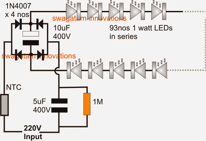
With 1 watt 350mA standard LEDs this would mean adding 310/3.3 = 93 LEDs in series, that's close to 100nos.
A single 1uF/400V capacitor produces around 60mA current at the above specified 310V DC, therefore for achieving the required 350mA more such capacitors will need to be added in parallel, to be precise a total of 350/60 = 5 capacitors, that could also be a single 5uF/400V but should be a non-polar type.
An NTC thermistor may be added for extra safety, although it may not be critically required.
Similarly a resistor could be also included to provide extra bit of safety from fluctuating voltage conditions.
The resistance value may be approximately calculated as R = Us - VFd/I = 310-306/.35 = 10 ohm, 1 watt
For a 120V input, the above specs would simply need to be halved, that is use 47nos of LEDs instead of 93, and for the capacitor a 5uF/200V would be enough.
Circuit Diagram
Warning: Circuits I have explained below are not isolated from mains AC, and therefore are extremely dangerous to touch in the powered and open condition. You should be extremely careful while building and testing these circuits, and make sure to take the necessary safety precautions. The author cannot be held responsible for any mishap due to any negligence by the user.
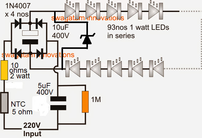
The above diagram can be additionally safeguarded from surge inrush voltages, and mains fluctuations by adding a 10 ohm limiting resistors and a zener diode, as shown below.
Here the value of zener diode should be 310V, 2 watt
Improved design with current control
The following circuit is a foolproof circuit design that will never allow the LEDs to come across a stressful condition. The mosfet and thee associated current control ensure 100% constant voltage and constant current for the connect LED bulb chain.
The number of LEDs in the chain can be adjusted as per the selected voltage, or conversely the voltage can be adjusted as per the selected number of LEDs in the chain.
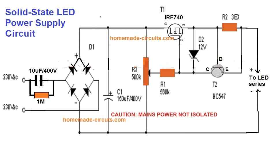
Note: Please move the capacitor C1 from the existing position to the output terminals of the circuit. Meaning, remove the C1 from across the bridge rectifier and connect it parallel to the LED string. This will drastically eliminate excess stress of the MOSFET, yet provide a filtered DC to the LEDs, increasing the overall efficiency of the design. In this case the voltage rating of C1 can be reduced to the value that's just slightly above the total forward voltage of the series LED string.


Questions & Answers
Good evening
What would be the value of the resistor R2 for a power of 200W leds? Thanks
Hello,
R2 = 0.7 / Maximum LED current
Merci beaucoup monsieur
Merci beaucoup Monsieur
My pleasure!
Or at the output of my dimmer made from a triac and which I have rectified, I can put the two components connected in parallel (1M resistor and 1u / 400V capacitor). I mount several 1u / 400V capacitors in parallel until the current is 1.75A?
Hello sir, as there is no 200V zener diode in our region, I used a dimmer to vary the voltage to 200V well rectified but the leds do not shine normally. Is the current insufficient? I assumed that the current for each led is 350mA and that there are 5 lines connected in parallel which constitutes a block of 5 lines connected in parallel, each line has 24 leds connected in parallel we have in total a current of 1 , 75A. As I have 2 blocks which are connected in series. How I can increase or amplify the current so that the leds shine normally
Hello Daoud, you will have to use a transformer based power supply which can supply 200 V 350 ma, or use an SMPS with the same rating. Capacitive method with zener diode will not produce 350 mA.
Also make sure each LED series has a limiting resistor calculated using the formula suggested in the previous email.
Merci beaucoup à l’aide que vous me donnez
Je vais donc faire comme vous l’avez dit en appliquant une tension de 200V. Merci infiniment
Good day, sir. Thank you for your help. In fact the projector of an unrecoverable switching power supply so I wanted to make another power supply. Of course I have already realized but the mosfet heats up a lot this mosfet is mounted in commutation. The led projector is 200W. How to avoid heating this transistor. This projector has 10 lines of 24 leds per line Thank you
Hello Daoud, assuming the LED series/parallel connections are correctly calculated, the heating up issue of the transistor can be simply solved by using a higher rated transistor, whose rating must be much higher than the total power of the LEDs.
Hello Sir thank you very much for your response. I used 2 mosfets of 150W with rds 1.2 Ohms resistor, the voltage Vds 900V and the current of 9A but it still heats up you can have an idea for that please. When I limit the current with a resistance of 500 Ohms the transistor does not heat it is the resistance which heats up earlier. Can I send you the diagram please?
You are welcome Daoud, 900 V and 1.2 ohm both don’t look compatible for your application. The VDD and ID can be at the most 1.5 times higher than the V and I specs of the series/parallel LED array. Higher VDD would also mean high RDSon which can cause the FET to heat up…..so try replacing with a MOSFET having specs only 1.5 times higher than the LED specs.
The limiting resistor must be optimally calculated, higher series resistance would unnecessarily reduce the light output of the LED.
Thank you very much Sir really I am very proud
And today I received a 180W led projector. Inside the projector we have 2 blocks of leds and each block contains 5 lines mounted in parallel each line includes 25 leds. Now the first block is mounted in series with the second block. The power supply of this projector is a switching power supply which is defective as components cannot be found on the market. I did a simple rectification then filter I obtain a voltage of 325V and I feed the projector it does not shine well. What can I do to shine well? Thank you for your help
Thank you Daoud, the formula for the supply voltage, limiting resistors, and the current is given below: The supply DC must be slightly higher than the total forward drop of the LED series, and LED series current can be equal to the single LED current.
Limiting Resistor = supply DC – total FWD voltage of the LED series / total LED current
If the total series LED number is 24 + 24 = 48 and each LED voltage is 3.3 V. Then the total forward (FWD) LED voltage becomes 48 x 3.3 = 158 V, and any DC above this value can be applied or a maximum of 200 V DC can be applied.
Please sir I need the schematic diagram of CTORCH LED 28W 2520Lm 250mA circuit diagram.AC input of 230-40V.
Thank you for your guided and kind response.
Charis, I don’t have the mentioned circuit….but you can use the second circuit from the above article, and put 28nos of 1 watt LEDs. The zener diode will be 92 V.
Hello sir want to run 25 number of 1 watt led in series wat will be the changes in circuit
Abdul, you can try the last circuit, adjust the voltage to 25 x 3.3 = 82 V
Thank you sir ,sir where i connect +ve input and -ve input ? Is the +ve can be connected in capacitor side? What is the specification of zener diode?
dear sir,
i made a tiktok ring light with 150 leds (1 watt 3.5 vold),27 leds were brightness and 123 leds were not bright,totally 123 leds did not work.it was without zener diod and varistor,please how to solve it?
Hello Shelim, without seeing the schematic I cannot judge the fault, so if possible provide the complete circuit diagram.
Ritesh, sorry actually I have updated the required diagram in the following article, please check it out
https://www.homemade-circuits.com/make-hundred-watt-led-floodlight/
Thanks sir, sir I can you help me by using smps ? Can you provide me that full circuit diagram and all specification of all components? Sir plz help me I am so excited about this project.
Ritesh, please tell me the total number LEDs, and the wattage of the LEDs you want to use for the project.
Thanks Sir,Sir I want to do a 100 watt LED lamp with 1watt LEDs .sir please give me proper circuit diagram and provide me full specification of all components used in this project. Sir plz help me kindly I am so excited to perform this project. Plz sir
Ritesh, I have updated the diagram above…you can check it out
Thanks sir, Sir I am very excited to do this project sir can you help me? Can you provide the actual practical circuit diagram of this project , with all components and all’s specification. Sir plz can you send me with full description?
Ritesh, I have undated the diagram, but please do it at your own risk, because mains current is always dangerous and you cannot predict it 100%.
If you want 100% guaranteed results then it is always better to go for an SMPS based power supply or a transformer based power supply.
Sir,As shown in circuit diagram can I connect the zener diode in parallel with 10uf 400v capacitor ? What’s the specification of zener diode ?where can I connect the heat sink and what’s the specification of heatsink
yes you must connect it in parallel to the 10uF/400V cap. The zener value should be equal to the total forward drop of the LEDs in series. Heatsink will need to be determined through practical experimentation
Hello Sir, thanks for your support , Sir can I know where the ntc is connected in +ve of input or in -ve of input ?and what is the specification of zener diode? and where I can use to the zener diode?sir plz kindly respond me.plz help me out
Ritesh, NTC can be connected anywhere in the line, either in the positive line or the negative.
zener diode can be connected parallel to the filter capacitor.
but make sure to connect a small value resistor, may be a 50 ohm 2 watt in series with the NTC.
Thanks Sir
Dear.. how are you sir i hope your healthy n fir ..
can can you provide me the circuit diagram of *manual heat sealing machine*
Nazim, the procedures involved are purely mechanical so I won’t be able to help you with it, since my expertise is lies only with electronic circuits
Dear Swagatam sir
Simplest 100 Watt LED Bulb Circuit.
1Watt LED
Forward current: 350mA
Forward Voltage: 3.2V~3.4V in average (3.3V*93Leds= 306.9V),
In india we are getting Indian power supply 240V 50Hz then how this circuit working.
My dought is input voltage is lower around 220V~250V and output Voltage is Higher (3.3V*93Led)=306.9V… how ita working sir
Hello Nazim, the 220V is the average value of the AC, alo called the RMS, the peak value of this 220V AC is always around 310V.
when we rectify this 220V with a bridge and filter capacitor, the 310V is produced and sustained at the output by these components, therefore the output that we get is 310V DC instead of 220V AC.
I hope you have a basic digital meter with you to check the voltages, which is a must for any electronic hobbyist.
I think 5uf is sufficient for led if the brightness is not getting sufficient then it may b led fault or any other fault in my circuit sir ? Im i correct sir
Im not get 310v 2watt zener diode in my local market so i let it and only 5uf +1uf again add totall 6uf then the above said situation happen.
Did zener diode controls the volts or Ampere sir?
did you connect a large heatsink with the LEDs? at 300mA the LEDs can get immensely hot and will blow within a minute.
without a zener the LEDs can burn with a slightest mains fluctuation.
zener will control voltage and will prevent rise in abnormal current consumption.
Dear Swagatam sir,
If i want to run 1watt 350mA led on 12-0-12 , 5Ampere transformer.
Q1 :- How can i run 1watt 350ma leds?
Q2:- What changes i have to done in above 100watt bulb circuit?
Q3:-how many leds can i operates with 12-0-12 5ampere transformer with out any problem to enter set?
In the previous 93led circuit i have add one 1uf/400v non polar capacitor then i give supply after some time 5to10mints leds become slowly dim by dim i think “1uf producing 70mA (70*5=350mA)
Dear Nazim,
connect then as shown in the last diagram of this article
https://www.homemade-circuits.com/make-this-1000-watt-led-flood-light/
each string will consume .3 x (3.3 x 6) = 6 watts
your transformer supply is 24 x 5 = 120 watts
so you can connect 120/6 = 20 such parallel strings
Hello sir,
I have made this tranformerless circuit using MB10S bridge rectifier. I have used 250v 1.1uf non polorised capacitor and 250v 10uf polorised capacitor with 470 ohm 1 watt resistor at output with series of 52 leds string. But at output i am getting only 37mA. When i need 60mA. When i tried using 250v 2.2uf non polorised capacitor it became so hot. And other thing is i have some size ristrictions for this driver so if i use 400v non polorised capacitor then it will be so big and will not fit in. So can you plesse give me dome solution over this problem?
Thank you.
Dipan, to get 60mA you will need a 2uF/400V capacitor. 400V is required for guaranteed safety to the capacitor so it is a must. For smaller size you can use 250V but that will not ensure a 100% safety for the capacitor.
Dear Swagatam sir
(Did i need to place between “6uf/400v ….(310b 2watt zener diode ?)…… 10uf/400v) right sir
Dear Swagatam sir
Simplest 100 Watt LED Bulb Circuit.
(Did i need to place between “6uf/400v ….(310b 2watt zener diode ?)…… 10uf/400v) right sir
Dear Nazim, yes connect ii across the same points where 10uF/400V capacitor leads are connected, anode of zener to minus of capacitor, cathode to plus pin of capacitor.
Dear Swagatam sir
Simplest 100 Watt LED Bulb Circuit.
310V 2 watt zener
in the above design circuit where i have to place the zener diode
waiting for your great replay sir thanks a lot sir. thank you very much sir
you can connect its anode with the negative line (-310V line) and cathode with the positive line (+310V line)