If you are looking for a multiple light effect generator circuit to generate sequencing, reverse/forward light effects, using 220 V colorful lamps, then this circuit might help you.
How the Circuit Works
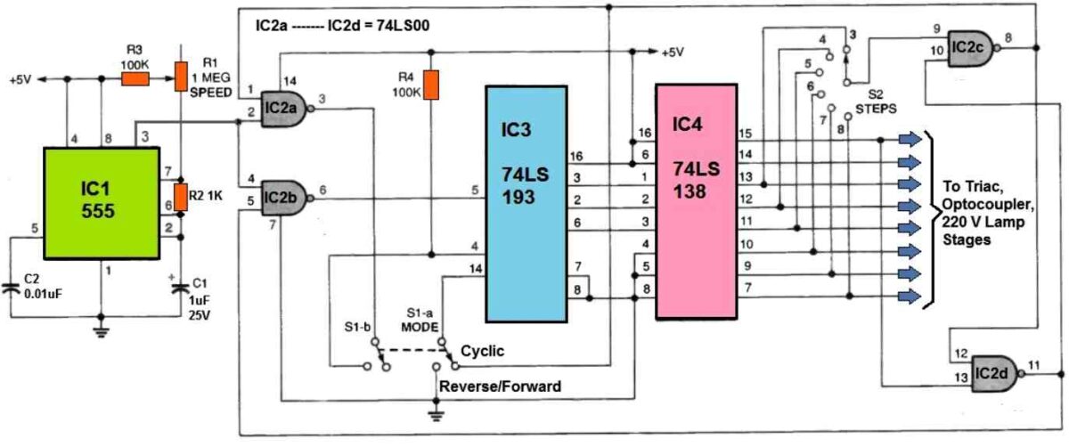
The following figure displays the Light Effect Generator circuit diagram.
This circuit has an oscillator, a few control logic stages, a 5 V DC input supply, and eight outputs for the opto-coupler, triac, and light stages.

The oscillator, 1C1, a 555 timer, is set up to control the repetition rate. The following formula determines the oscillator's frequency:
f = 1.44 / (R1 + R3 + 2R2) x C
The numbers displayed fall within a frequency range of around 1.3 Hz to 14.1 Hz. The fastest speed may be adjusted by adjusting potentiometer R3.
IC3, a binary up/down counter, is the brain of the circuit's logic control.
The circuit's output sequencing mode is selected using switch S1. When in cyclic mode, IC3 functions as an up-counter which is reset upon reaching the very end of the sequence. While operating in reverse/forward mode, IC3 starts counting until the last point in the sequence before counting back down.
Quad NAND gate IC2 guides the clock pulses from the oscillator to the up/down counting pins of IC3. By combining IC2c and ICd, a flip-flop switches IC3's reverse forward mode between up/down counting. When cyclic mode is selected, IC2 controls IC3's reset and upward counting inputs.
The 3 to 8 line binary decoder IC4 decodes the binary outputs of IC3. Rotary switch S2 is wired across the decoder's final six outputs. The number of positions or steps in the sequence could be selected using this switch. These decoder outputs are also utilized to energize the eight power control circuits, which are responsible for controlling the light strings.
A 4 to 16 line decoder (such as a 74LS154) might be used to produce 16 steps in the circuit rather than 8 since IC3 is a 4-bit up/down counter. Nevertheless, in order to use this light effect generator circuit, a rotary switch with additional settings would also be required.
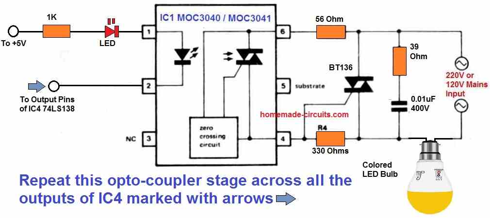
Lamp Control Stage

A BT136 triac, a MOC3040 opto-coupler, and a red 20 mA LED constitute each of the eight power-control circuits. In addition to isolation, the opto-isolators also offer zero-crossing detection and triac driving circuits. Each triac will switch on at the precise moment when the AC voltage is zero volts, instead of at the AC peak voltage. Thanks to this zero-crossing function, which safeguards the light bulbs.
Construction
Mount the sockets for the IC1-1C4 and IC6-1C13 first.
Next, carefully position the polarized capacitors and solder all of the fixed resistors and capacitors to the pcb. Insert the bridge rectifier, being careful to position it correctly.
Next, connect the two switches and the potentiometer. You must attach short, insulated leads to the pcb to enable connections to the sockets, fuse, and AC cable.
Solder the eight LEDs to the board to finish up the construction. Ensure the LED bases are roughly 3/8 inch away from the PCB since it will be directly affixed to the cabinet's front plate using 1/2 inch spacers. The lenses will get to the front panel that way.
Next, solder the eight triacs to the circuit board.
The opto-isolators should then be inserted into their sockets. The tracs will need to be bent so that they are less than half an inch off the board.
Opto-isolators must be fitted before bending over the triacs because otherwise, the triac's heatsinks will partially enclose them. Ensure that the triacs and LEDs are positioned properly.
Final Assembly and Testing
Set aside a space for testing and position the assembled board so that it doesn't come into contact with any of the high-voltage parts of the enclosure.
Switch ON the device, then examine that the switches, speed control, and LED display are all working properly. When the device is powered up, use caution to avoid touching the circuit board.
During final assembly or debugging, unplug the circuit from the power source. If the device isn't working right, ensure all polarized parts are oriented correctly.
Using the Light Effect Generator Circuit
Extreme caution must be used when using the light effect generator circuit since it runs on 220V AC, which increases the danger of electric shock. Please place the device where it will remain dry while you set this up.
Each output may accommodate a number of light threads. However the power-control circuit's safe current limit is around 1 ampere, or 220 watts. Under no circumstances must the 1 amp fuse rating be increased.
Lamp strings may be arranged into various patterns and figures on cables or wooden structures to create various interesting animation effects. Additionally useful structures for lighting shows and effects include trees and fences. Even moving holiday messages are possible by constructing letters out of various light strings.
Keep experimenting with the two modes (using S1 and S2) and the speed potentiometer of the light effect generator circuit to see which one suits your needs the most. You'll quickly be putting up gorgeous decorations and enhancing the festive season in your area!
Post your comments here and get guaranteed replies. Comments must be related to the above article.