Testing and troubleshooting electronic project circuits requires a multimeter, so new hobbyists may feel interested to try the following homemade multimeter circuits as their next electronic project.
Using a Single Opamp 741
The few opamp based meter circuits such as Ohmmeter, voltmeter, ammeter are discussed below using the IC 741 and just a few other passive components.
Although multimeters are available plentifully in the market today, building your own homemade multimeter can be real fun.
Moreover the attributes involved can become thoroughly useful for the future electronic circuit building and testing procedures.
DC Voltmeter Circuit using IC 741
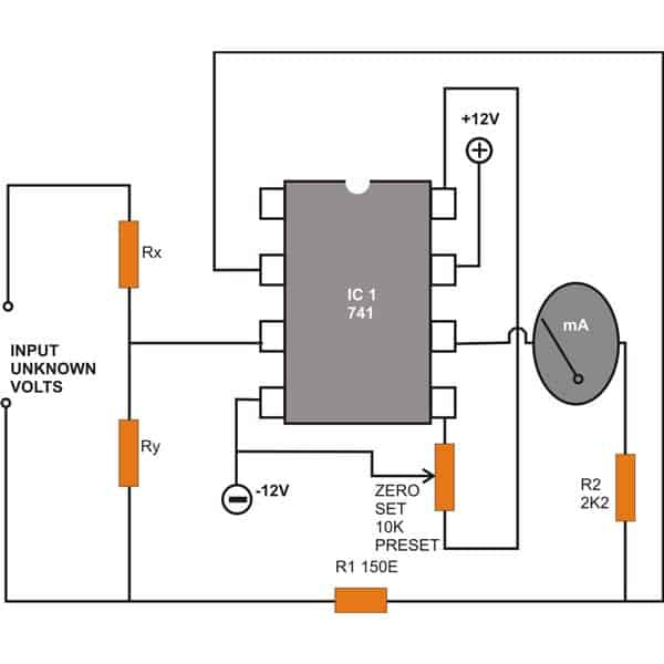
Note: The lower end of the zero-set preset is mistakenly connected to pin#8 of the IC, please connect it to pin#1 instead.
A simple configuration for measuring DC voltages is shown above using the IC 741.
A couple of resistors Rx and Ry are introduced at the input in a potential divider mode at the non-inverting pin #3 of the IC.
The voltage to be measured is applied across the resistor R1 and ground.
Through proper selection of Rx and Ry, the range of the meter can be varied and different voltages can be measured.
AC Voltmeter Circuit using IC 741
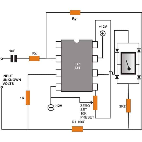
Note: The lower end of the zero-set preset is mistakenly connected to pin#8 of the IC, please connect it to pin#1 instead.
In case you want to measure alternating voltages then the circuit illustrated above can become useful.
The wiring is similar to the above wiring, however the positions of Rx and Ry have changed and also a coupling capacitor comes into the scene at the inverting input of the IC.
Interestingly the meter here is now connected across a bridge network enabling the meter to display the relevant AC potentials correctly.
DC Ammeter Circuit using IC 741
Another circuit to measure Direct current or Amps using the IC 741 can be seen in the following figure.
The configuration looks pretty simple. Here the input is applied across the resistor Rz i.e. across the non-inverting input pin #3 of the IC and the ground.
The range of the meter can be simply varied by changing the value of the resistor Rz.
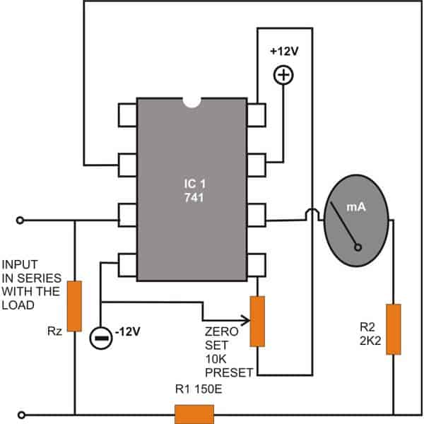
.Note: The lower end of the zero-set preset is mistakenly connected to pin#8 of the IC, please connect it to pin#1 instead.
Ohmmeter Circuit using IC 741
Resistors are one of the most important passive components which inevitably become an integral part of every electronic circuit.
A circuit may be virtually impossible to build without accompanying these amazing current controlling devices.
With so many resistors involved, a possible fault can always be on the cards.
Identifying them requires a meter – an Ohm meter. A simple design using the IC 741 is shown below just for the purpose.
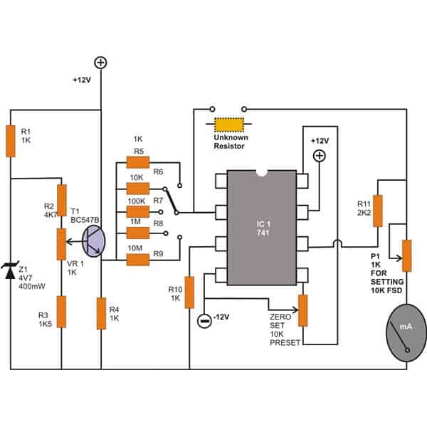
Note: The lower end of the zero-set preset is mistakenly connected to pin#8 of the IC, please connect it to pin#1 instead.
Unlike most of the analogue designs which tend to have a rather non-linear behavior, the present design very efficiently tackles the problem to produce a perfectly linear response with the corresponding measurements.
The range is pretty impressive, it can measure values of resistors right from 1K up to a staggering 10 M.
You may go on to modify the circuit for enabling the measurement of more extreme values.
The range is selected by moving the rotary switch switch into the relevant positions.
How to Calibrate the Meter Circuits
Calibrating th instrument is simple and is done with the following points: Adjust the selector switch to the “10K” position.
Trim the base preset of the transistor until its emitter voltage shows exactly 1 volt (measure using a digital multimeter.) Next, Fix an accurately known 10 K resistor into the measuring slot.
Adjust the trimmer associated with the moving coil meter until the meter shows a full scale deflection.
All the circuits discussed above use dual supply voltages. The meter used is a moving coil type and is specified as 1mA FSD.
The preset across the pins 1, 4 and 5 of the IC 741 used for this homemede multimeter is used for adjusting the initial condition meter to exactly zero. Relevant Values of Rx and Ry The following are the values of the resistors required for varying the range of the respective meters.
DC Voltmeter
Rx--------------------Ry--------------------Meter FSD
10M-----------------1K--------------------1KV
10M-----------------10K-------------------100V
10M-----------------100K------------------10V
900K----------------100K------------------1V
NIL-------------------100K-----------------0.1V
DC AMMETER
Rz--------------------Meter FSD
0.1-------------------1A
1---------------------100mA
10-------------------10mA
100-----------------1mA
1K-------------------100uA
10K-----------------10uA
100K---------------1uA
AC VOLTMETER
Ry---------------------Rx-------------------Meter FSD
10K-------------------10M----------------1KV
100K-----------------10M----------------100V
1M-------------------10M-----------------10V
1M--------------------1M------------------1V
1M--------------------100K----------------100mV
1M--------------------10K------------------10mV
1M--------------------1K--------------------1mV
A request from one of the keen followers of this blog:
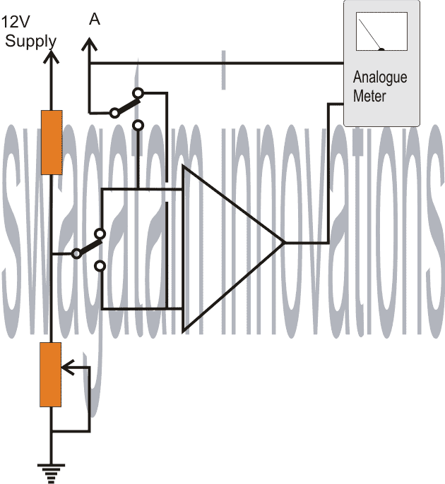
Is it possible to design a small circuit module which can be used with a multimeter to measure minimum/maximum voltage of a fluctuating signal at any point of a circuit under observation.
For example, we can switch a toggle switch in our module at MIN position and measure the voltage at point (A). The volts shown by the multimeter would be LOWEST voltage of the signal.
And when the toggle switch is positioned at MAX, and the voltage is measured again at point (A) the meter will show the HIGHEST voltage of the signal.
The Design


Questions & Answers
Dear Sir,
Pl. go through this DMM circuit using 7107.I want LCD display DVM and I suppose only 7106 is good for that. I want PCB or the same as I am unable to design one for this schematic. If someone could provide me one! as he has not done the same in the page.
https://www.homemade-circuits.com/wp-content/uploads/2025/02/digital-multimeter-circuit.jpg
I am not a Electronic student and of chemistry. I don’t know how to design the needed PCB. Hence I requested in my last letter.
In Ic 741 Work bench multimeter can we change the analog signal to digital using Tl 071 IC and then feed it to LCD display/
please understand my problem.
Thanks and best regards.
Hello mahandharma,
sorry PCB designing will not be possible for me. But yes you can get any readymade digital meter and replace it with the analogue meter in the above IC 741 circuit. Readymade digital meter modules are cheaply available on amazon.
Can you create one with 7106 IC and LCD display> of course complete range with temperature indicator also.
Thanks.
You can try the following circuit. If you connect an LM35 IC with its input, it will work like a temperature meter.
https://www.homemade-circuits.com/make-this-simple-digital-voltmeter/
Hi there,
do you have PCB and LCD display circuit for this Digital multi meter and let me know if i could use old DVM LCD with box for this item.
Hi, sorry I do not have the PCB and LCD display for these circuits…
You can make this circuit? It’s works? Since you make a connection of the potentiometer or preset to a terminal 8 of IC 741, this terminal is marked with NC (Not connected) in the datasheet.
OK, Yes, that’s a drawing mistake, the offset null preset pin must go to pin#1 of the IC and not to pin#8.
That you for pointing it out.
I will put a correction message in the article soon.
Good.
Hi sir, I'm using dt9205a multimeter, everything else is working correctly in that multimeter, but when I set to AC range limit 750v ac, it starts reading itself before connecting anything, and reaches upto 120v ac probes are connected to nothing.
Hi Abhishek, it looks like your meter's selector switch is having loose contact or the AC range is faulty…try putting a little oil inside the selector switch's ball-bearing and see if that helps.
Dearest Sagatam,
How might one obtain an output in small voltages rather than 1mA FSD so that I could use an Arduino to switch scales and display the results instead of an analogue needle?
Thanks,
–Tom
Dear Tom, you can achieve this by replacing the ammeter with a wire link and connect an appropriately calculated (V FSD) across the R2 resistor. This resistor value may be altered for matching the FSd of a particular voltmeter.
Thanks a lot for the answer! Sorry a lot for the questions…:-( hope you understand..and by the way…
1. Where can I put the fuse?
2. What is dual voltage?
3. You mean Rx and Ry in ac/dc voltmeter determines the MAX. range? and Rz for ammeter?
4. Can I use your ammeter to test 220v mains?
5. Is there a way to increase the max range of ammeter? How?
1. connect it in series with the input supply which needs to be measured.
2. see the second diagram in the following link:
https://www.homemade-circuits.com/2012/01/how-to-make-hi-fi-100-watt-amplifier.html
3. yes that's correct
4. no, it's not designed to measure mains curret
5. range can be increased by decreasing the value of Rz
Good day sir!
1. If I want my voltmeter to measure 1V to 1KV will I use a coil meter with a scale of 1v to 1kv?
2. For DC voltmeter if I use Rx-10M, and Ry-1K the max will be 1KV, right? and what is the min. volts?(for short what is the range?) .
3. How many amps can the ac and dc voltmeter hold?
4. Can I put fuse for ac and dc voltmeter?
5. What is 150E?
6. Can I use 9V battery?
7. How about the range of ammeter?
8.How many volts can ammeter hold?
Good day Eshkariel,
yes coil meter ca be used
yes that's right,mimimum will be zero obviously.
amps is irrelevant when it's being used for volts, it doesn't matter.
yes fuse can be included for safety.
150E = 150 ohms
9V batt will do but use two for creating dual voltage for the IC.
ammeter range will depend on Rx, Rz.
volt is irrelevant when it being used as a ammeter.
Hello, Could you tell me please a circuit is able to detect impedances starting from 0.01 ohm to 10ohm max?
Putting a resiatenza switch 100 ohm resistive part of the value from 2ohm to 10ohm maximum?
I would need for a very important project but I can not find it anywhere!
Thanks
please Google "milliohm meter circuit" you'll get plenty of circuit ideas.
Hello, I find her very interesting pattern, I would like to ask you a question: To measure an impedance of 0 ohms to 10 ohms in the selector R5 – R9 resistor value should I enter? Thanks for the help
Hello, i don't think the shown design would be capable of sensing such small resistance values….no ideas.
is it possible to use this with 2 9volt batt. ?
how can i best modifie for measuring 2 ohm to 10 ohm.?
tnx
yes 9v batts can be used…..use a 100 ohm resistor in the selector switch array for checking 2 to 10 ohm
-is it possible to use 2* 9volt batt?
-i want to modifi it to measure 3ohm to 16 ohm ,what should i change ,appart from r5-9 ?
E’ possibile usare il circuito dell’ohmetro in un multimetro fai da te con uscita per un voltmetro digitale? E’ stabile la lettura?
It should be an ammeter at the output, a voltmeter will not work. Yes the circuit is stable…
Forse mettendo un carico per 1 mA e misurando la tensione relativa funzionerà?
Yes, that might work…
Grazie per le risposte