• Skip to primary navigation
  • Skip to main content
  • Skip to primary sidebar

Homemade Circuit Projects

Get free circuit help 24/7

  • 1000+ Circuits
  • Privacy Policy
  • About Us
  • Contact
  • Disclaimer
  • Videos – Circuit Test Results
You are here: Home / Meters and Testers / Testing Alternator Current using Dummy Load

Testing Alternator Current using Dummy Load

Last Updated on December 28, 2019 by Swagatam 1 Comment

The post explains a method of checking or verifying alternator maximum current delivering capacity using a shunt regulator as the dummy load and an ammeter. The idea was inquired by Mr. Joe.

Circuit Question

I need help designing an electronic dummy load that can handle high enough power from motorcycle alternator.

I need to know how much power is available from the alternator because when I first time finished rewound the alternator, it shows me 7A of power from two winding set (my alternator is modified by adding another winding on outer layer of existing winding).

But now it only shows about 4A of power from the two winding set. Is it best to use electronic dummy load or just simple resistive load as resistive load is only work in certain voltage range (that's what I know) to test the alternator.

Kindly need your help for the circuit design.

Thanks and regards,

Joe

Assessing the The Design

Hi Joe,

did you try using your digital mulltimeter with a shunt regulator.

You can set the meter to the maximum current range, normally this could be at 20Amp AC range and check the results by connecting its prods at the output of the shunt regulator and input of the shunt with the alternator winding output. This should provide you with the necessary information??

The Design

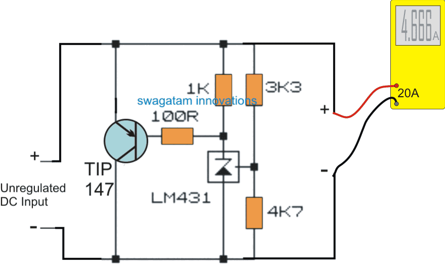
I have already discussed a simple shunt regulator circuit in one of my earlier posts, we can implement the same shunt regulator circuit as a dummy load for the proposed testing of alternator current, through an ammeter in series with the shunt device.

Although an ammeter can be directly connected with the alternator output for measuring its current capacity, a shunt regulator ensures a controlled measurement of the measurement over a specified voltage limit.

Meaning if the alternator is rated to generate a fluctuating voltage say from12V to 24v, the shunt regulator could be set to dump the excess voltage above 12V and control the alternator voltage at this level.

However for the meter this might have no notable effect except a little stress-free working due to the controlled voltage level.

The following circuit shows how to use a shunt regulator as a dummy load with a ammeter for testing alternator current safely and accurately.

Circuit Diagram

Circuit for Testing Alternator Current using Dummy Load


Previous: Autoclave Heater Controller Circuit
Next: Force Sensing Resistor Explained

About Swagatam

I am an electronic engineer (dipIETE ), hobbyist, inventor, schematic/PCB designer, manufacturer. I am also the founder of the website: https://www.homemade-circuits.com/, where I love sharing my innovative circuit ideas and tutorials.
If you have any circuit related query, you may interact through comments, I'll be most happy to help!

You'll also like:

  • 1.  Simple LED VU Meter Circuit
  • 2.  Function Generator Circuit using a Single IC 4049
  • 3.  How to Measure AC Milli-volts Using IC 741
  • 4.  Arduino Frequency Meter Using 16×2 Display
  • 5.  Universal BJT, JFET, MOSFET Tester Circuit
  • 6.  LED Brightness and Efficiency Tester Circuit

Please Subscribe (Only if you are Genuinely Interested in our Newsletters)


Reader Interactions

Comments

    Your Comments are too Valuable! But please see that they are related to the above article, and are not off-topic! Cancel reply

    Your email address will not be published. Required fields are marked *

  1. Search Related Posts for Commenting

  2. Mark says

    thanks Swagatam understaning much more about avr just cycling around to understant avrs better …no need to reply answer some ones question THANKS

    Reply


  3. COMMENT BOX IS MOVED AT THE TOP


Primary Sidebar

Electronic Projects Categories

  • 3-Phase Power (15)
  • 324 IC Circuits (19)
  • 4017 IC Circuits (51)
  • 4060 IC Circuits (25)
  • 555 IC Circuits (92)
  • 741 IC Circuits (18)
  • Amplifiers (49)
  • Arduino Engineering Projects (82)
  • Audio Projects (84)
  • Battery Chargers (75)
  • Car and Motorcycle (87)
  • Datasheets (45)
  • Decorative Lighting (Diwali, Christmas) (31)
  • DIY LED Projects (81)
  • Electronic Components (97)
  • Electronic Devices and Circuit Theory (35)
  • Electronics Tutorial (99)
  • Fish Aquarium (5)
  • Free Energy (34)
  • Games (2)
  • GSM Projects (9)
  • Health Related (17)
  • Heater Controllers (23)
  • Home Electrical Circuits (98)
  • Incubator Related (6)
  • Industrial Electronics (26)
  • Infrared (IR) (39)
  • Inverter Circuits (94)
  • Laser Projects (10)
  • LM317/LM338 (21)
  • LM3915 IC (24)
  • Meters and Testers (54)
  • Mini Projects (153)
  • Motor Controller (64)
  • MPPT (7)
  • Oscillator Circuits (12)
  • PIR (Passive Infrared) (8)
  • Power Electronics (33)
  • Power Supply Circuits (66)
  • Radio Circuits (9)
  • Remote Control (46)
  • Security and Alarm (56)
  • Sensors and Detectors (115)
  • SG3525 IC (5)
  • Simple Circuits (72)
  • SMPS (30)
  • Solar Controllers (60)
  • Timer and Delay Relay (51)
  • TL494 IC (5)
  • Transformerless Power Supply (8)
  • Transmitter Circuits (38)
  • Ultrasonic Projects (12)
  • Water Level Controller (45)

Follow Homemade Circuits

Facebook
Twitter
YouTube
Instagram
My Facebook-Page
Quora

Feeds

Post RSS
Comment RSS

Circuit Calculators

  • AWG to Millimeter Converter
  • Battery Back up Time Calculator
  • Capacitance Reactance Calculator
  • IC 555 Astable Calculator
  • IC 555 Monostable Calculator
  • Inductance Calculator
  • LC Resonance Calculator
  • LM317, LM338, LM396 Calculator
  • Ohm’s Law Calculator
  • Phase Angle Phase Shift Calculator
  • Power Factor (PF) Calculator
  • Reactance Calculator
  • Small Signal Transistor(BJT) and Diode Quick Datasheet
  • Transistor Astable Calculator
  • Transistor base Resistor Calculator
  • Voltage Divider Calculator
  • Wire Current Calculator
  • Zener Diode Calculator

© 2021 · Swagatam Innovations