The circuit presented here monitors the level of the water rising inside a tank and automatically switches OFF the pump motor as soon as the water level reaches the brim of the tank.
The proposed tank water overflow controller circuit is a semi automatic device because it can only sense an overfill and switch OFF the motor but cannot initiate the motor when water supply is introduced.
The user has to switch ON the motor pump manually when water supply becomes available or during pumping out of water from other sources like a bore well or a river.
Water Level Control Using Transistors
The circuit uses only transistors, is very simple and may be understood with the following description:
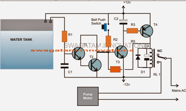
The CIRCUIT DIAGRAM shows a design involving only transistors and a few other passive components.
Transistors T3 and T4 along with the associated parts forms a simple latch circuit.
When the push button is pressed momentarily, T2 gets forward biased and provides the required biasing to T4 which also instantly conducts.
When T4 conducts, the relay activates and the motor pump is switched ON.
A feedback voltage from the collector of T4 reaching the base of T3 via R4 ensures that T3 remains latched and in a conducting mode even after the push button is released.
Once the water reaches the threshold level of the tank it comes in contact with a pair of terminals positioned at the desired height inside the tank.
The water connects the two terminals and a leakage voltage starts flowing through them which becomes enough for triggering the Darlington pair made up of T1 and T2.
T1/T2 conducts and immediately grounds the feedback signal at the base of T3.
T3 is inhibited from the biasing voltage and the latch breaks switching OFF the relay and the motor.
The circuit remains in this position until the water inside the tank goes below the sense terminals and the push button is initiated yet again.
PLEASE CHECK THIS CIRCUIT FIRST BY CONNECTING A LAMP IN PLACE OF THE MOTOR.
POWER THE CIRCUIT THROUGH A DC 12V SUPPLY.
START BY PRESSING THE SWITCH, THE LAMP SHOULD LIGHT UP.
NOW MANUALLY DIP THE TWO SENSING WIRE TIPS IN WATER, THIS SHOULD INSTANTLY SWITCH OFF THE LAMP AND BRING THE CIRCUIT INTO ITS PREVIOUS POSITION.
Parts List
R1 = 1K,
R2 = 470K,
R3 = 10K
R4 = 1M (it's situated just below T3)
T1, T2, T3 = BC547,
T4 = BC557
C1 = 0.22uF
C2 = 10uF/25V
C3 = 100uF/25V
D1 = 1N4148,
Relay = 12 volts/SPDT
Push Button = Bell push type



Questions & Answers
I made it only with a BC547 and a BC557 pair, The darlington pair is not necessary…..
my setup is different though, the motor is connected to the Normally Closed contact of the relay and so both of the transistors are off while the motor is running. working flawlessly for about a year!
Did you remove R1 and C1 as well?
Thank you for updating the info, glad it is working flawlessly.
Hi Sir! Do you have a fully automatic version of the circuit above?
how can i modify it to start the pump automatically every time the water level is dropping?
Hi Amor, yes I have a few designs posted in this website, you can find it here:
https://www.homemade-circuits.com/2011/12/how-to-make-simple-water-level.html
Hi Sir, sorry i sent a wrong question. i am looking for a fully automatic water level controller circuit using just a single float switch placed at the upper part of the tank. i prefer using a float switch to avoid corrosion using probes.
but i want the water tank to always full, then the circuit must work right away every time the float switch is being activated due to water dropping. is this possible Sir? thanks.
Hi Amor, yes that can be easily implemented with some modifications to one of the circuits mentioned in the following page, you can select the one which suites you the best:
https://www.homemade-circuits.com/?s=float+switch
hi . thanks for your ckt diagram and information. i am trying to develop this ckt but getting one problem. whenever i am making power on, relay is energizing instantly. i try to only t3/t4 pair even its also energizing relay.
i read above comments and try to find d2 but its not mention in your ckt.
please help…
tausif
Hi, You can correct it by removing C2 from its existing position and bringing it across the base/emitter of T3. That will immediately solve the issue.
even same problem after changing c2. i am testing t3/t4 ckt. now removed r4 and open that ckt means no wire connected to base of t3. still getting energized after power on.
then it means your t4 has problems, or may be some other connection issue.
You can refer this article for more info:
https://www.homemade-circuits.com/simple-and-useful-transistor-latch/
yes i was doing mistake in reading of ckt diagram. so it was not working. after correction it was working but had problem. problem : whenever i touch sensor wire in the water it was energizing relay and when disconnecting it switch off relay . so i remove t2 now it is working fine. thanks for your response.
OK, glad it worked for you!
still having same problem after changing position of c2 across the base/ emitter of t3
Hi, thanks for the design.
I made the above circuit exactly as shown in the schematics, but i am having the following problem:
The circuit powers on normally, the bulb lights on when the push button is pressed, when the sensing wires are inserted in the water the bulb doesn’t turn off, as soon as the wires are taken out of the water the bulb turns off. If i insert the wires back in the water the bulb lights up again.
Hi, try joining the sensor points manually with a screwdriver or any conductor and see whether that breaks the latch or not?
Check this then I’ll tell how to confirm the next steps…
When i connect the sensor wires manually, nothing happens at first but as soon as i disconnect them the bulb lights up. I mean sensor wires are working in opposite manner.
when you press the switch T3/T4 will latch and the relay will switch on the load which can be a test bulb.
when the T1/T2 base is connected with positive line, T1/T2 will conduct and ground the base of T3, breaking the latch and also breaking the relay operation so that the load is switched OFF.
This is how the circuit is designed operate.
Hello, Any update please.
can i design it in proteus 7 professional??
please refer to all the comments above and build it accordingly, this circuit is too simple for an issue….
I tried this circuit and it is working. but having small issue, I build circuit by removing T2 and added 1N4007 to emitter of T3, R1-10k R2-47k, R3-10K, R4-1M.
Problem
——-
1) Latch (T3 and T4) is too much sensitive when I touch to probe of R2, Relay get on. how to fix this issue ?
2) I have 12v adapter when I plug in AC board, Relay get automatically on (I observed that this happen when there is sparking during plug in AC board. If I plug adapter when AC current is off it work (means relay will not on))
kindly advise
I tried but did not succeeded. I have shared file please check and kindly suggest changes.
https://drive.google.com/file/d/0B6ZCUggMmnSRbTlIeGVCbVZfcFE/view?usp=sharing
T3 cannot conduct unless the switch is pressed, because with the switch in the open condition T3 base will be also open and therefore it can never switch ON. I think your PCB design has some problem, please go back to the breadboard again and compare the two step-wise to locate the fault
Need one more help. I have build circuit on bread board and it is working fine. I design same on PCB board but I am facing below issue.
1) Relay will automatically switch on after 10 min. (even in simulator software it behave same) where as on bread board it is not like that, Relay will not switch on automatically.
In simulator I observed that bast voltage of T3 gradually increase and T4 conduct.
please help.
can you please provide your email ID I will send you circuit design.
Bingo….! it is working now 🙂 thanks a lot.
Increase the value of C1 to 1uF, or may be to 4.7uF and check the response!
Forgot to mention even R3 changed to 10K.
thanks for updating, I am glad it's working for you. initially I had only one transistor for T1/T2 but when a few of the members complained that T1 was not responding to water, I had to create a Darlington in that position.
Thanks to you for providing such a nice and simple circuit.
Yes true, initially it did not work for with only T2. Then I added T1 and It started working but was not holding the latch completely. There was a 2-3 sec delay of latch hold after which it gets released even without touching of the probes.
Then I tried the whole circuit from scratch without T1 which resulted in a working circuit but the response of probes was not too good. Then read through this blog and understood the problems of others, which led me to change the values of R1, R2, R3 and R4 as mentioned above in my first comment. These changes brought the circuit to a stable state and work perfectly. Now I am using 2N2907 instead of BC557 as it has better gain factor.
thanks again for sharing the experience, I am sure this will help the other readers.
Recently tried this circuit and is working very nicely, but with some variations. R4=47K, R2=47K, R1=10K connected to base of T2, removed T1, transformer used 9-0 500mA which outputs to 12V, 500mA after bridge rectification.
Reason for removal of T1 is the darlington pair of T1-T2 is causing it to be too sensitive such that even no touch causes the latch of the T3-T4 to fail bringing the relay back to normal. Even 1k for R4 does not help in providing a strong latch.
As suggested to put a diode after emitter of T3 was not tried by me, as removing T1 is working superb for me.
I tried 10mtr wire for the probes in tank and 1M for R1 and still no issues in releasing the latch when water in tank is full, though the response becomes slow. Hence for my need I am using 15K for R1 which gives a 1 sec response. Reason for this delay is I do not want the latch to be released immediately when the probes conduct through first touch of water as the motor/pump water keeps the water in tank move up/down, hence a 1 sec delay brings the water level to a stable state such that the probes are completely immersed in water and release the latch completely.
It is Necessary to connect to the 12v DC Battery….
DC from a 12v AC/DC adapter…not a battery
Hi Swagatam
First of all thanks for the above circuit, i understood the latch circuit from it, but didn't understand the use of capacitors in the circuit, im implementing this circuit in another circuit.
So plz explain the role of capacitors.
Thanks 🙂
Thanks Ahmed,
C1 is to ensure that T1/T2 activates only with water not by any external electrical disturbance.
C2 makes sure that the latch does not operate on power switch ON, but only when the push button is pressed.
C3 prevents the relay from chattering durign the activation thresholds.
Hello sir thanks for your guidance. Every thing works great. I am so happy that first time i can make any circuit with your help and guidance. Thanks for it.
Now plz solve my another problem. My sumbersible pump have a circuit box to start the pump and there is push on/off buttons. Plz help me how can i attach the circuit to that box
..and also make sure that the 12V ACDC adapter gets it power from the actuator output.
That's great Amandeep, Congrats to you!
for integrating the above circuit with the actuator box, you will need to do the following modifications:
remove C2 entirely from the circuit we don't need it.
replace the push button with a 0.1uF capacitor.
let the motor be connected as shown in the above diagram, just transfer the "mains AC" points shown in the diagram with the output of the actuator box….meaning the mains AC will enter the actuator box first and then enter the above circuit relay connections and the motor.
make sure the relay is appropriately rated, and use TIP32 in place of T4 if the relay is too big.
Thanks for quick reply
Hello sir, how r u?
Once again i am back to ask you about my query. First i want to thank you about helping me to make above circuit for water overflow control. I made the above circuit and it works great. Just there is need to add a diode between emitter of T3 and negative of 12 v. Which you already mentioned in you conversation with other. Thanks very much
Sir now my query is that, how can i make 12v dc from 12 0 12 transformer. Where should i connect capacitor. And what value of capacitor should i use. At present i am using 12 v adapter for circuit which is sealed and i can't see the circuit diagram of adapter. Plz help me to make my own 12v from 12 0 12 transformer.
One thing more, can i use 12 v transformerless supply, which can be create just by use of some resistors and capacitor. I see it on YouTube. Is it safe to use 12v transformerless supply rather than use of transformer??????
Sorry for mistakes in writing in English if any.
Thanks
Amandeep
I am glad to hear this Amandeep, thanks for updating the info!
for the 0-12V power supply you can select any two wires among the three from your transformer secondary but make sure it includes the center wire, meaning take anyone of the outer wires and the center wire,
next make a bridge rectifier and connect it with these wires.
once you have done this you can connect a 470uF/25V filter capacitor across the output of the bridge network and then finally terminate the same to the supply rails of your circuit.
No, a capacitive transformerless power supply is not recommended for this circuit because it's not isolated from mains voltage and might result in lethal shock across the output wires of the circuit.
Sir
I used Icircuit app in my mobile. When I was used R1,r2,r3,r4(1m,1k,10k,100k) ohm and c1,c2,c3(0.22,100uf,100uf) and SPDT 12v DC relay then it is parfectly worked. But I am confused that it will work practically .
if correctly adjusted, it will work 100% correctly, we just have to check all the crucial nodes of the circuit and tweak the results through some trial and error until it works as per the expectations.
the design is very simple and adjusting the parameters shouldn't be difficult at all.
Now the circuit is very erratic for some reason. Sometimes it triggers only when i push the button sometimes it always ON, sometimes it does not power on at all. Im not able to figure. I tried to restore back the old resistor below T3. I have also connected a LED which is always ON and no change when the circuit is OFF also.
correction: use 1uF for C2, not T2 it's a typo.
connect LED on the following places for getting an idea regarding the fault, because normally this latch circuit is very reliable and will not behave erratically.
connect red LED in series with the emitter ground of T3
also, replace C2 with 1K resistor and bring C2 across the base emitter of T3, use 1uF for T2 instead of 10uF
connect another LED parallel with the relay coil with a 1K resistors in series.
if still it gives prblems then you may have to opt for an IC circuit
I've connected the circuit as indicated in the diagram and also connected a push button across T3 base & ground (Works fine but I have to hold the button till the latch releases..May be 3-4 Seconds). But for water full condition the circuit does not power off. Please guide me through.
make the resistor just below T3 larger, may be upto 1M and check….