In this post I have explained how to make a chasing "WELCOME" display circuit sign board, which illuminates each alphabet sequentially until all the 7 alphabets are lit and then the whole display shuts off, the cycle continues permanently as long as the circuit is powered.
Overview
I have already discussed a similar concept explaining a bar graph display LED circuit for car turn signal, the same idea is implemented for the present welcome chasing light display circuit.
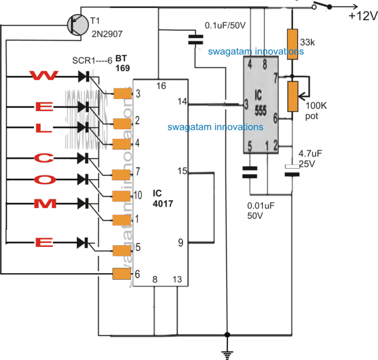
The figure below shows the details of the circuit:
Circuit Diagram
Parts List
All Resistors are 1/4 watt 5%
- SCR gate resistors are all 1k.
- T1 base resistor is 1k
- 33k = 1no
- potentiometer 100k = 1no
- Capacitor 4.7uF/25V/Electrolytic = 1no
- Capacitor 0.1uF/Disc = 1no
- Capacitor 0.01uF/Disc = 1no
- T1 2N2907 = 1no
- IC 4017 = 1no
- IC 555 = 1no
- SCR BT169 = 7nos
How it Works
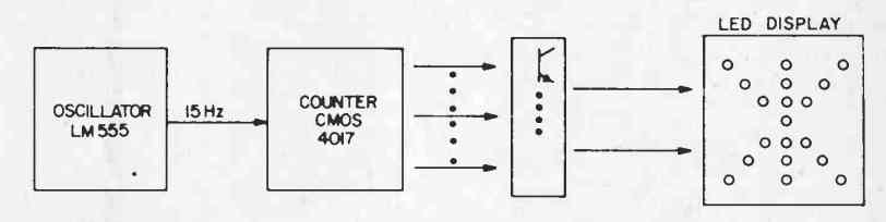
Referring to the circuit above, the entire design is configured around a standard IC 4017, and IC 555 chaser circuit, wherein the IC 555 transmits the required sequences clocks at pin#14 of the IC 4017 and enables a sequential chasing of the high logic across the selected output pins of the IC 4017.
Here the pinouts from pin#3 and pin#5 are rigged for illuminating the "welcome" display while pin#6 is used for resetting the sequence after each complete cycle.
Meaning once the whole "welcome" sign is lit, subsequently pin#6 triggers the 2N2907 to switch OFF the SCRs and reset the sequence from the beginning at pin#3.
The 4017 IC outputs sequence with a "jumping" high logic which switch ON only momentarily while shifting from one pin to the next, this implies that if the LEDs were connected directly with the pinouts would cause each alphabet to illuminate only for a moment until the next alphabet was lit, enabling only one alphabet to be lit at a given instant. This would make the display unreadable and the "welcome" sign would be unrecognizable.
In order to ensure that all the alphabets are lit and stay latched during the sequencing, SCRs are introduced with the pinouts for illuminating the LEDs.
The SCRs trigger and latch during the sequence until all the the alphabets are illuminated and then finally shut off to begin a new sequence.
The IC 555 generates the clocks for the sequencing, and the speed of the sequencing can be adjusted through the associated 100K pot.
How to Wire the LEDs for Creating the WELCOME alphabets
Now I have explained how all the alphabets involved in the display may be wired using many LEDs in series and parallel connections.
Since the supply for the circuit is around 12V to 15V, and assuming the LEDs are 5mm/20mA type red LEDs, wiring groups of 4 LEDs in series seems to suit the best.
The following example figure clearly illustrates how the letter "W" may be wired using groups of 4 series LEDs, and connecting these 4 LED strings in parallel, such that the final outcome resembles the letter "W".
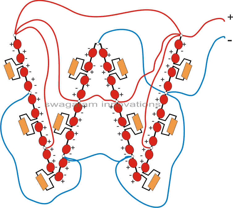
In the same way other alphabets could be easily configured and wired together for developing the required "welcome" chasing LED display circuit.
The series resistors across each of the 4 series LED string can be calculated using the linked software.
All LEDs are red LEDs/5mm/20mA/High Bright
For 4 LED series the resistor value will be = 25 Ohms 1/4 watt
If there are 3 LED series the resistor value will be = 175 Ohms 1/4 watt
If there are 2 LED series the resistor value will be = 330 Ohms 1/4 watt


Questions & Answers
For SCR we can use transistor….?
Pls tell the difference of SCR & TRANSISTOR…it will work only in DC…
TRIAC will work only in AC…
MOSFET will work in DC..?
Sometimes I'm confused seeing some circuits in web….so pls explain sir…
transistors will not latch and not hold the illumination, that's why SCRs are used which will latch and keep the LED locked until broken through T1.
SCR and triac will work with AC, without latching….but in DC they will latch with one trigger.
mosfet and BJTs can never work with AC.
How can we operate 500 leds from a transister having 10v at base.
Transistor is3053 npn.
what is your supply's voltage and current rating??
Thank u sir …for your nice and good explanation
One more doubt sir
1.While giving single postive trigger 1 second to Scr ..it will conduct….?
2.When we give continues postive trigger scr will damage ?
3.SCR & TRIAC latch continues means we can use for alarm circuit…when small postive trigger apply to gate…it will make continues alarm….
…
1) yes single trigger will latch the SCR
2) multiple triggers will not damage the SCR
3) we can use this feature for making security alarm which I have already published in this website
Here the resistance value with SCR not marked.pls specify value of registace
you can use 1k resistors
Sir pls send the lind address
here are the links
https://www.homemade-circuits.com/2012/03/how-to-make-simple-scr-application.html
https://www.homemade-circuits.com/2013/02/make-these-simple-cheap-home-burglar.html
I make this circuit but not work properly pls send me any link or send me video link
Thanking you
Dear sir
what problem are you getting? you should first check using single LEDs with 1K resistors, and then wire the alphabets accordingly for the final integration
Hi Swagatam,
My question relates to the 555 resistors. I have previously used 4.7K for the 33K, 100K pot and 10uF for the 4.7uF with success in the past. What is the real difference between the two configurations? Just trying to learn. Thanks!
Hi Norman, the resistors and capacitor associated with a 555 astable are all related with each other and together influence the final outcome…therefore you can change and tweak the values of these components as per your preference and get any desired frequency level at the output….the values just needs to e proportionately matched, how the proportion is matched is not critical
you can try the second design in the following software for learning more
https://www.homemade-circuits.com/p/ic-555-calculator.html
Hi Swagatam,
I asked a question a couple of days back and I can't remember where I asked it, so I am asking again under this post. My question is: can I use 2-12vdc power supplies in series to light 24v strip LEDs? The seller sent me 24v strip LEDs instead of the 12v I ordered. I'm trying to figure out how I may use them. Thanks!
yes, I have answered it in the same post.
You will need a boost converter circuit for the purpose which seems to be the most appropriate solution for your specific requirement…
Sr how we identify gate anode and cathode in scr.suggest plz
Madina, If you hold the SCR with its printed side towards you and leads downwards, the right side lead is the gate, the center one is the anode, and the left side pin is the cathode
Well detailed tutorial,of great help boss..thanx
Thank you Juzer!!
230v led “welcome ” bord diagrams please sir
use a 220V to 12C DC adapter with the above explained circuit…
we need total component list out sir
I have updated the required details in the article…
Thanks sir
Dear sir,
In your drawing, Why we put resistor in the middle? It’s count 2 series or 4 series?
Without the current limiting resistors the LEDs may burn…
Yes, but why in middle?
How if i direct connect series resistor and leds into adaptor?
The strings of 4 LEDs or 2 LEDs are connected in parallel, so each of these strings must have its own limiting resistor for equal light/current distribution.
The position of the resistor is not critical, you can connect it after the 1st LED, or the 2nd, or anywhere as long as it is in series with the specific string
Well done sir,
For that WELCOME project Can I use triac in place of scr, because I didn’t see scr. thanks
yes triac can be used
You are truly a blessing in my life. Thanks for all help you are rendering.
Thank you sir!!!
It is my pleasure Ismail!
Sir can I use 2n3906 instead of (T1 2N2907 = 1no) because I could not find one.
Thanks
Ismail, 2N3906 will not be OK because it can handle only 60 to 100 mA without heating, you can try BD140 instead
Sir! There is one signboard in my area and it was written on it;
……………………….
. R & B .
. QUEST HOTEL .
………………………..
Firstly, the circuit will illuminate R, &, B, QUEST, and finally HOTEL and LEDs that circled it sequentially. And then finally blink all of them three times.
Can you please help me with the circuit diagram, because I don’t know how it was made
Note: the dot dot dot…above Represent the LEDs that round the text.
Thanks
Ismail, please do the following modifications to the schematic shown in the first diagram!
1) First replace the LED/resistor modules attached to each of the SCRs with a 2.2k resistor. So we now have only the 2.2k resistor resistor as the load on each of the SCRs
2) Configure another transistor T2 (BC557) and wire it exactly like T1 except its base which must be connected to pin#11 of the IC….and pin#15 of the IC must be connected to the ground line.
3) Connect all the positive side free ends of the 2.2k resistors with the collector of T2.
4) All the the series/parallel LED configurations for each of the specified phrases should be connected in parallel to the respective 2.2 k resistors.
5) The sequential operations of the mentioned phrases will end at pin#1 of the IC.
6) Configure another IC 555 astable flasher with flashing rate of 2 Hz rate, and connect its pin#4 with ground line via a 10k resistor, and also connect pin#4 with pin#5,6,9 of IC4017 through individual 1N4148 diodes, cathodes will join together and connect with pin#4 of the IC 555 flasher.
7) Connect Pin#3 of the IC 555 flasher with the base of the T1
Thank you for taking the time to be kind. You have a great heart. Thank you. I will start building the circuit now.
You are welcome, and all the best to you!
you can do it by following instructions as explained in the following example article
https://www.homemade-circuits.com/200-600-led-project-on-mains-220v/
Hello. I tried this and works…expect one of the letters doesnt stay on. It lights up but turns off when the next lights up. I tried a few scrs but no luck. Can you tell me what im doing wrong?!
Thank you
Glad the circuit is working for you. You can connect the faulty SCR/LED network with another output pin of the IC 4017 and check the response. Meaning, you can interchange the faulty SCR/LED network with an adjacent SCR/LED network and check the response. If still the problem persists then the problem could be with your specific SCR/LED network which will need to be checked by a meter.
Dear Swagatam,
The circuit for ‘WELCOME’ is very good. Now that Diwali is round the corner. If some circuit for ‘HAPPY DIWALI’ with sequential lighting the words and then all words flashing thrice and then again starting from beginning is shared will be appreciated.
Thanks & Regards
Thank you Ashok,
It seems the same above circuit can be used for “Happy Diwali” also but the last letters LI will need to be illuminated together, because the IC 4017 can handle only 10 letters, or we may have to cascade two 4017s together. If it is possible I will try to post it in this website soon.
Do I need to change resistors values if I use pink led’s? They’re rated for 1 volt higher than red ones. Pink are 3.2 volt.
Thank you very much for all of your effort. I’m new and learning a lot here.
Yes the resistor value will need to change depending on the LED forward voltage rating.
You can use the following formula to determine the resistor value.
R = Supply Voltage – Total forward Voltage of the LED string / LED current.
Let’s assume the supply DC is 12V, and the number of LEDs on each string is 3 and the forward voltage of each LED is 3.2V. This will cause the total forward LED voltage to be 3.2 x 3 = 9.6V, also let’s assume the LED current is 20 mA. Then the above formula can be solved as given below:
R = 12 – 9.6 / 0.02 = 120 ohms
Power = 12 – 9.6 x 0.02 = 0.048 watts or simply 1/4 watt.
Dear Swagatam,
I made a sign for my girlfriend with 5 letters. In addition to the letters, I made two hearts. Each heart is made of thirty Red 3mm 2.0 – 2.2 volt led’s.
I want the hearts to pulse on/off continuously while the letters cycle, preferably with a fade effect to make them look more like beating hearts. I want them to be powered by the same 12 volt source as the letters circuit.
I made a fader circuit with a 555 timer and bc547 bjt, and it actually works pretty satisfying. However, I’m struggling to get good voltage measurements across my resistors to make sure I have correct current through the led’s. I’m worried it will suddenly fail.
I know it’s a lot to ask, but can you show me what your approach would be? or maybe you have something more clever than the 555 fader circuit.
Thank you soooo much!
Thank you Bill,
Glad you could make those interesting circuits successfully.
To calculate the LED series resistor value correctly, you can use the following formula:
R = (Supply Voltage – Total LED forward drop) / LED max current tolerance
Please let me know if you have any further questions or doubts.
Hi Swagatan, How would you go about finding a fault in the above given circuit? Lets say that the sign is out of eye or a person does not really notice that the sign has gotten a broken letter, how would you go about setting up such that as soon as there is a disturbance (broken light/letter), i get an output and then that output can be used in any way to notify the owner such as a light or sound or even more complex to send an email notification suggesting that there is a fault and the location of the fault?
Hi M You,
Detecting a broken letter can be extremely difficult. Broken letter would mean one or two LEDs not illuminating which will make no difference to the circuit parameters so detecting this difference can be almost impossible.
If a few LEDs shut off there will be a small current increase but this difference can be impossible to detect with a simple circuit.
Thank you very much for your answer, greetings Jiří
You are welcome Jiří…
Dear Mr. Swagatan, please write to me how many light-emitting diodes I can connect to the BT169 thyristor without damaging it.
I would like to create a large Christmas motif from 350 multi-colored LEDs, which I will connect to a cascade of 2 IC4017B with about 13 outputs.
Thank you for your answer. Greetings Jiří.
Hi Jiří, the BT169 can handle a maximum of 0.5 amps or 500mA current, so you can connect LED strings not exceeding this value. The total current of the LED string will depend on how you configure them with series and parallel connections.
sir iam Srinivas from andhrapradesh, india.
sir is there any alternative circuit at bt169. bcoz I have bt 136 in my hand . pls let me know this. I struck at this point…help me in this
thank u
Hi Srinivas,
You can use C106 SCR, if BT169 is not available to you…BT136 is a triac which won’t be appropriate for the above circuit…
Sir actually I need more current output to connect more leds in series parallel combination ..pls suggest any transistor circuit or MOSFET circuit
Srinivas, Transistors will not work because single transistors cannot latch, SCRs can latch.
A C106 SCR can handle many LEDs, more than 500mA capacity.
c106 is not available at my area sir. pls suggest any alternative circuit for this output section…
thanks for ur prompt response…
sir can I use tyn608 or tyn612 type scr inplace of bt169
Hi Srinivas, yes it can be used, though it is rated at 8 Amp which is an overkill for such small LED loads, requiring not more than 1 Amp max…