A Negative Temperature Coefficient (NTC) thermistor is a device which is able to suppress switch ON current surge due to its initial higher resistance at room temperature.
However, as the NTC suppresses the initial surge current, it warms up causing its resistance to drop to nominal levels and this in turns allows the current to flow through it at an acceptable rate, and the connected load is able to work normally.
In this post I have explained how to use an NTC thermistors in circuits for suppressing surge current during power switch ON. We also learn the datasheet and the electrical specifications of an NTC.
Today electronics is getting more and more compact and light weight, it's basically due to the involvement of compact converters which have completely eliminated the age old iron cored transformers.
However, this had to come at a cost, these units became too vulnerable to switch ON power surges.
But electronics always has appropriate answers, whatever may be the issues. NTC thermistors were created exactly for tacking this, that is in-rush surge currents during power switch ON.
What's an NTC
NTC (Negative temperature coefficient) thermistor is a semiconductor that contains metallic oxides.
It displays an electrical resistance which has an extremely foreseeable alteration with warmth.
The resistance differs substantially with heat, much more in comparison to
normal resistors.
These are incredibly perceptive to heat change, very precise and interchangeable.
They possess a broad temperature envelope which enable it to be hermetically packed to be used in damp conditions also.
Main Features:
* Durability of service, superior stability
* Compactness, robustness, sturdy surge current resistance
* Quick reaction time to surge current
* Extensive operating spectrum
* Significant element constant (B value), minimal stay resistance.
How does an NTC Functions
An NTC is attributed with a special property through which it is able to raise its resistance significantly during power switch ON.
When used in electronic circuits this property helps blocking the initial surge currents in to the connected circuit.
However in the process, the NTC becomes relatively warmer, which brings down its resistance to lower levels such that the normalized safe power subsequently is allowed to pass over to the adjacent circuits.
Practical application:
Thermistors are commonly used as
* Inrush current limiters
* As Temperature sensors
* In the form of self-resetting over current protectors
* In self regulating heating elements
* Power Converters, switch mode power supply SMPS, UPS power protection
* Energy efficient lights, electronic ballasts and chokes,
* Many vulnerable electronic circuits, power supply circuits etc.
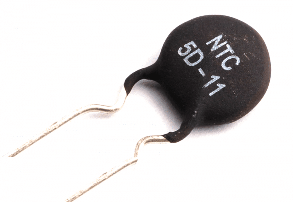
The following image shows an example NTC component:
Identifying the NTC Thermistor from its Print Mark:
Before learning how to use an NTC thermistor, the users must first know to read the label and the rating of the device. The first digit "5" indicates the resistance of the part at normal conditions. Here it indicates 5 Ohms.
The subsequent alphabet and the digit indicate the diameter of the particular part, here it's 11mm.
How to Connect an NTC Thermistor in Practical Electronic Circuits
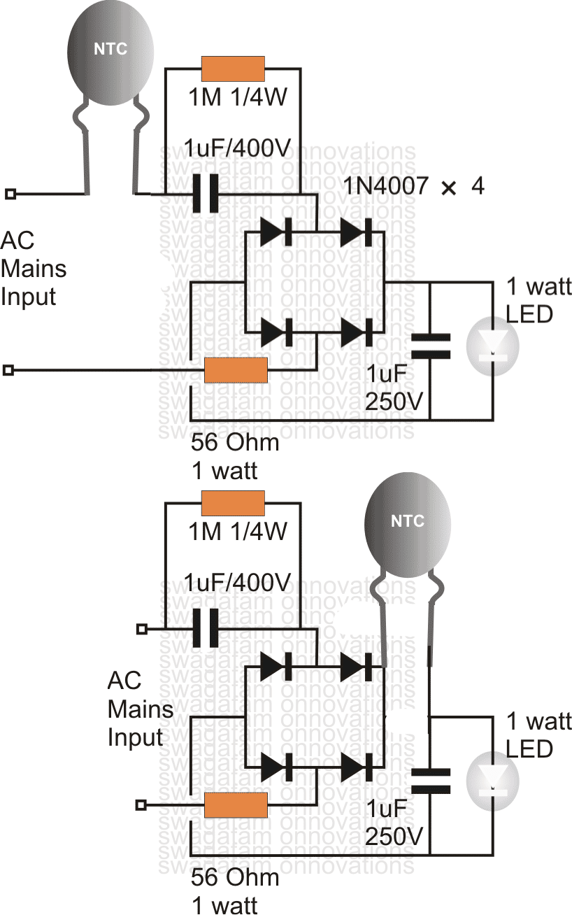
Normally in an electronic circuit an NTC is connected at one of the mains inputs, in series.
Alternatively, an NTC may be also used by connecting the device after the bridge rectifier, as shown in the following examples of surge controlled compact transformerless 1 watt LED driver circuits.
Filter Capacitors and NTC
The main issue related to current surges in switch-mode power supplies is a result of the large filter capacitors employed to filter the ripple in the rectified 60 Hz current before getting chopped at the high frequency.
The picture below shows a circuit generally found in switching power supplies.
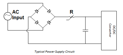
In this schematic the highest current during power switch on is the peak line voltage divided by the value of the resistor R.
For mains supply of 120 V AC, this can be roughly 120 x √2/R.
In the best possible scenario, just when Power is switched ON, the value of the resistor R needs to be much bigger, and quickly after once the mains supply is in its normal state, the R value must drop to zero.
An NTC thermistor is designed to work quite in this way, and therefore is best suited for most power supply application.
The job of an NTC is to limit the initial switch ON surge current by working like a power resistor that drops from a high value cool resistor to a low value warm resistor, the warmth being created by the normal current flowing through it.
NTC Considerations
A few of the aspects that needs to be considered while using NTC thermistor as an inrush current limiter are:
- Highest allowable surge current during Power switch-on
- Finding the equivalent thermistor size with respect to the the filter capacitors
- Maximum value of the current during it staeady state and normal continuous operation
- Highest possible ambient temperature around the thermistor
- Maximum expected life of the power supply
Maximum Surge Current
The major intent behind restricting inrush current is always to protect the electronic components that are connected in series with the input line of the DC/DC converter.
Generally, inrush protection inhibits annoying blowing of fuses or tripping of circuit breakers and sometimes burning or fusing of the of switch contacts.
Since the majority of thermistor elements are extremely ohmic at any assigned temperature, the lowest no-load resistance of the thermistor is computed by dividing the peak input voltage by the maximum permissible surge current in the power supply
Normal NTC Resistance = Vpeak / Imax surge
Turn-ON Current Surge
As soon as the input AC of an SMPS is switch-ON, all the associated filter capacitors inside the SMPS act like temporary instantaneous short circuit points, which store a charge equivalent to 1/2CV2 .
This sudden and instantaneous large inrush of current due to the the capacitors storing the charge has to make its way through the NTC.
Due to this the NTC temperature rises rapidly during this period, and as a result its resistance drops which ensures that subsequently when the capacitors are charged the NTC will stop restricting any further current and allow the current to reach the load normally.
The total time taken by the capacitors to charge optimally is dependent on the voltage.
The amount of current surge or power surge the NTC will be able to tolerate, fundamentally depends on the "mass" of the NTC.
The above logical view can be justified with the following expression and formula:
Input Energy = Energy Stored + Energy Dissipated
Pdt = HdT + (T – TA)dt
where:
- P = Amount of power developed inside the NTC, t = Time
- H = Capacity of the thermistor to heat up
- T = Thermistor body Temperature or the Dissipation constant
- TA = Ambient temperature
During the brief moment while the capacitors are charging (normally lower than 0.1 second), hardly any power is dissipated by the NTC.
Almost all of the input energy is adjusted as heat within the thermistor body.
In standard charts for inrush current limiters you can find outlined an advisable value of maximum capacitance at 120 V and 240 V.
This rating is not really meant to specify the overall capacities of the thermistors; rather, this indicates a practical value over and above which there can be some decrease in the life span of the limiter device.
Maximum Steady-State Current
The maximum steady-state current rating of a thermistor is mainly decided by the practical life of the power supply unit, for which the thermistor is being used and selected for protection.
In the steady-state situation, the balance of power in the differential equation explained earlier boils down to the below given heat balance formula:
Power = I2R = (T – TA)
As higher and higher current passes through the limiter device, its steady-state working temperature increases and its resistance decreases.
The highest current rating corresponds to the maximum permitted temperature.
In the standard inrush current limiters tables you will find a list of resistance values with respect to the load for each device, and also a recommended optimum steady-state current.
These ratings are dependent on standard PCB heat sinking, without considering the air ventilation, within a ambient temperature of 77° (25°C).
Having said that, the majority of power supplies include a reasonable air flow, which means a further increase in the the safety margin in addition to what is actually included in the maximum current rating.
In order to derate the maximum working steady state current with an increased ambient temperatures, you may make use of the below shown equation:
Iderated = √(1.1425–0.0057 x TA) x Imax @ 77°F (25°C)



Questions & Answers
yes 50 Leds 8mm will work with a 105 cap.
it's not critical, you may apply any value above 10uF, but the voltage rating should be above 50V preferably.
200V, 1 watt
Hello sir,
How r u.Its long time to have some discussion with u
I want to use ten 1watt led.can the above circuit is capable of this.
I had 10d-9 ntc can i use it for above circuit.i had seen some smps for powering dth and similar using
this value 10d-9 ntc.
Thanks
I am fine Avijeet, thanks!
The above circuit will illuminate 10 one watt LEDs in series but the glow will not be optimal due to lower current from the cap, yet still it would be considerably dazzling.
yes the referred NTC will do the job
Thanks for ur reply sir,
Can we add more 1u400v cap in parallel. If yes then any change with 56 ohm resistor and 1u250v in output
No adding more caps will not help much unless you make the total forward drop of the LEDs to near 220V.
yes it can be a good solution to the ever present surge problems in capacitive power supplies, I'll try to come up with a suitable circuit soon, and update in this blog.
Thanks!
When it comes to capacitive power supplies there are many things that needs to be considered. Just taking care of the zero crossing won't help
here we need to exploit the voltage rather than the current, because here we have plenty of voltage and less current.
Avoiding current means avoiding surges, so we have to thing of using minimum current which can be achieved by connecting LED in series.
For 20 watts instead of using a single LED, we can go for 20nos 1 watt LEDs in series, that would restrict the max current need to 300ma, quite achievable with smaller caps.
Next we also need to employ some sort voltage regulation by including 7812 or similar device in the circuit.
But ultimately as you have mentioned an smps is always good for anything that exceeds 100mA usage….and I have always recomended the use of an smps for making high watt LED drivers
sir i want to ask you two questions the first one I have deleted all of the thermistor how to identify the value and power of it, the second I want to know how to lock the increased flow of tiristor thermistor protected thanks
I don't think it can be measured with a DMM, we have to depend on the manufacturers spec sheet for knowing the details of these devices.
…sorry could not understand the second question?
Sir,
What Is the resistance value of that NTC…..
PLZ….
Avik, The one which is shown in the diagram is exactly what is required for this circuit….. in fact it's suitable for all 220V operated circuits.
Thanks
Sir,
can i put 10sp 005 thermistor in that Circuit? I already have that..
PLZ……..
I can't interpret its resistance value, you can try it, because slight variations in the resistance won't affect the circuit outcome shown above.
Hi,
I need this circuit use for 7 or 9 High Power LED in series, so what I need to changed. only the resistance power increased or change the value as well?????
connect the leds in series, no changes would be required, use it as it's given in the diagram.
which circuit isbest for home usage with 4 1 watt led
4.bp.blogspot.com/-Ao044-f_094/USJX2xXmq9I/AAAAAAAADLw/QXbrfjnDjHc/s1600/surge+protected+led+driver+circuit.png
vs
4.bp.blogspot.com/-e4z26LacoE0/UyAwhV1_YUI/AAAAAAAAGd0/3pFdlNxV9PE/s1600/1+watt+led+driver+circuit.png
Put NTC in the second circuit and use it for getting best results.
thanks Sir,I do as your answer ita woring very well.
Another Question is that if i connected single 3 watt Led instead of 4 1 watt leds can this circuit work
4.bp.blogspot.com/-e4z26LacoE0/UyAwhV1_YUI/AAAAAAAAGd0/3pFdlNxV9PE/s1600/1+watt+led+driver+circuit.png
Another ? is that can single 3 watt led is equal to 3 1 watt leds
Harjot, using less number of leds in series will make the circuit less efficient and using more numbers in series will improve its efficiency.
a single 3 watt led will produce an illumination of just 0.5 watt LED with the mentioned circuit
for perfect results you should go for an SMPS AC/DC adapter with a current control stage.
yes a single 3 watt LEd = 3 x 1 watt LED
Hello Sir,can you haveSMPS AC/DC adapter with a current control stage
Hello Harjot, presently i don't have but I'll try to post one related article soon, if possible….
thanks sir another question is that if i use 4 no of 5 watt led instead of 20 no of 1 watt leds for making an illumination of 20 watt cfl can this circuit work
4.bp.blogspot.com/-e4z26LacoE0/UyAwhV1_YUI/AAAAAAAAGd0/3pFdlNxV9PE/s1600/1+watt+led+driver+circuit.png
May be you did not understand what I suggested in the previous comment. In capacitive power supplies using less number of LEDs will reduce efficiency and light….using more number of LEDs will improve.
Therefore it would be better to use 20nos 1 watt LEDs instead of 4nos 5 watt LEDs which will not give any illumination
….more LEDs in series will improve…and less will reduce the efficiency and light
Hello swagtam , bro I have 1 9w led driver I want to add ntc in this for better protection. Can u plz tel me where I can ad ntc in main connection on phase or nutrel actually on line point it already have fuse resistance so cn I ad ntc on nutrel point. ?plz clear my doubt.
Hello Manoj, An NTC can be added on any of the input terminals, whether it's phase or neutral doesn't matter, you can even connect it in series with the fuse, nothing is critical as long as the device is in series with the supply line.
Dear sir'
no NTC(5 d_11) in my area
what i will do?
Dear Hasan,
I think your local retailer will know better regarding a standard equivalent, or alternatively you can try using a hand wound coil for obtaining the same results.
wind 500 turns of any thin super enameled copper wire over an iron bolt and use in series with the LED.
Sir'
I have got thermistor DSC(10 D-13).can I change c2(1uf 400v).
pls reply
yes you can do it, no problem…
Dear swagatam'
1. How many give LED(5mm) in this circuit?
2.Can you a very better LEDcircuit ask me?
pls help me.
Dear Hassan, you can add upto 90 LEDs in series for a 220V input, and 45 LeDs for 110V
Tanks Sir'
1.can I put only 20 or 25 LED(5mm) in the circuit?
2. Sir can you more better (1or2watt)LED circuit ask me?
yes 25 to 39 5mm LEDs will also work, but you may need to change the input capacitor to 0.47uF/400V
for higher watt LEDs you should opt for SMPS driver
Sir' very tanks.
Sir can I use 50 nos of 5mm leds in series for this circuit I have blinking leds (dual color led) like red blue and red green
yes you can use it.
Sir i want to run 300 leds of 5mm or 8mm to 230v AC main of 6 series in parallel means each series of 50 leds so wat will be the changes for the circuit
use 2uF/400V instead of 1uF/400V
Ok thanx sir
Hello sir, I have a charging fan that uses NTC 10D-9 in its power supply. It was a new fan and it worked fine for one month and after that its fuse burnt out so I replaced it with new one but the new one burnt out as soon as I turned on the switch. I have tried to search for the short circuit but there is any short circuit. now I believe that it is because of NTC it is not limiting the current. can you please guide me that what ever i m believing is right ?
Hello Aneel, an NTC is connected in series to the input line, so it cannot be a cause of a short circuit, still you can remove it and check by connecting a 100 watt bulb in place of the fuse, if the bulb glows and the fan does not move, then surely your fan could be the culprit.
Sir.
Can i use MOV 10D471k or Which value would be safe to use?
Satheesh, please check the clamping voltage of the MOV from its datasheet….if it's around 330V to 400V it would be fine.
Sir
Thank you for your advice on how i say it does not compensate. The only thing I can do. Can I pray for you. You always have wealth.
there's no way to check whether an MOV is actually working or not,,,,but in most cases it will perform as expected from it.
pray for the world!…God bless you!