In this article I have explained a simple infrared (IR) remote control circuit which is configured for operating a DC motor in response to the switching made from a standard IR remote handset such as a TV remote or a DVD remote.
The connected motor can be moved either ways and also can be made to halt.
The circuit may be understood with the following explanations:
How it Works
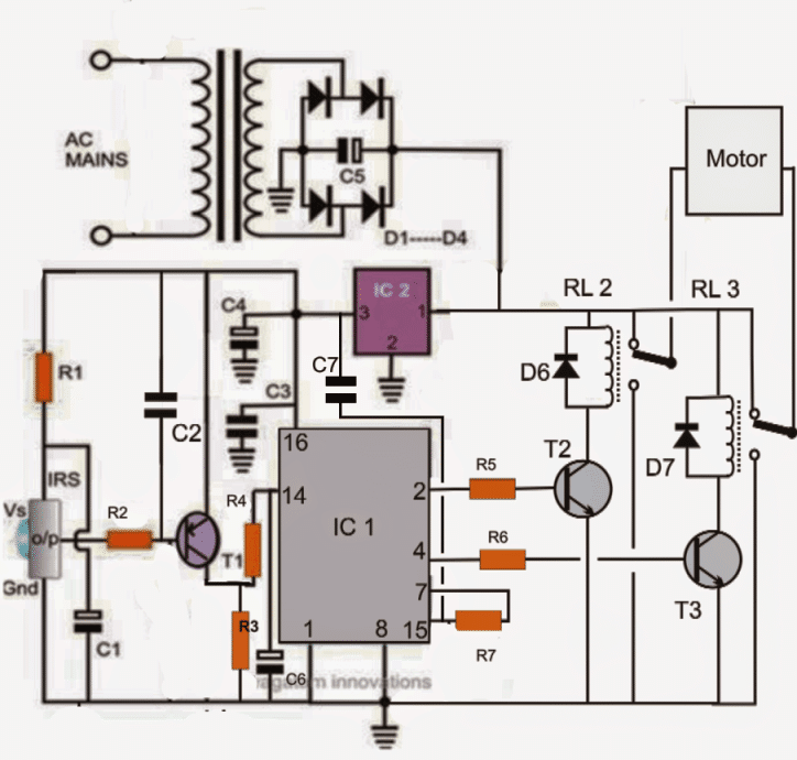
As can be seen in the given circuit diagram, the sensor is any standard three pin IR sensor module which would typically respond to any TV IR remote handset.
When an IR (infrared) beam is focused at the sensor, the pin which is designated as the output becomes logic low. This situation persists as long as the beam remains focused at it.
The transistor T1 which is a PNP responds to this logic low signal and conducts switching the attached relay RL1.
The contacts instantly connect the instantaneous positive potential at the collector of the transistor to pin#14 of the IC1 which is wired as a flip flop circuit.
Assuming the initial logic sequence to be at pin#3 of the IC, the above triggering shifts the sequence to pin#2 of the IC, making it high.
This switches ON T2 and the corresponding relay RL2.
RL2 conducts and connects the particular wire of the motor to negative supply. Since the other terminal of the motor gets a positive from RL3, it starts moving on the set direction.
Now suppose, the sensor is given a subsequent trigger through the IR remote handset, the above process repeats and the output sequence shifts from pin#2 to pin#4 of IC1, which instantly switches ON T3 while switching OFF T2.
The above action reverts the relay connections forcing the motor to instantly flip its rotational direction .
With another subsequent trigger from the remote handset, the sequence bounces of back to pin#3, which is not connected to anything and results in switching off of the motor completely.
The inclusion of L1, C1 ensures that the circuits does not get influenced with spurious triggering of the sensor.
L1 can be experimented to get the optimal value so that it "grounds" only accidental stray external signals and not the actual IR signals from a remote control handset.
Parts List for the above IR (infra red) remote controlled motor circuit.
R1 = 100 ohms,
R2 = 1K
R3,R4,R5,R6,R7 = 10K
C1, C4,C6 = 100uF/25V
C2,C3, C7 = 0.22uF
C5 = 1000uF/25V
C6 = 0.22uF
L1 = 100mH choke
T1 = BC557
T2,T3 = BC547
D1---D7 = 1N4007
IC1= IC4017
IC2 = 7812
All relays = 12V/400 ohms/SPDT
sensor = TSOP1738
Motor = 12V Dc motor


Questions & Answers
I am Daniel from KENYA. Have a question – under infrared (IR) motor remote control circuit, in a circuit using IC – BA 6209 (linear 10 pin), where pins no.5 & 6 (Forward In & Reverse In) connected in an already constructed circuit? Could you kindly design for me the IR circuit to incorporate, and use remote control to control the system volume with a 12volts motor? I have already constructed the circuit, connected the motor to volume control with gears. Now need IR remote control circuit to increase or lower the system sound level using remote control. Shall profoundly appreciate, to know the next circuit diagram linking my already made, to control sound level remotely. Thank you.
Daniel, you can do this: Use a TSOP1738 IR receiver with an Arduino Nano. Decode the remote signals and use two output pins to drive pin 5 and pin 6 of BA6209 through 1k resistors. One output will rotate the motor forward (volume up) and the other reverse (volume down). Ensure common ground and avoid activating both inputs together.
Let me know if you want the full diagram with the code?
Hello, just a question for research: Can we convert a purely continuous voltage of 400V DC into a purely alternative voltage of 230V / 50Hz AC, with of course “N” channel MOSFETS controlled by ICs and without voltage transformer? If possible some explanations for me.
Yes that’s possible using any of the concepts explained in the following link:
https://www.homemade-circuits.com/5kva-transformerless-inverter-circuit/
Hi, I am a student and I'm willing to try this project; what about if I want to control two 24V motors? Can it be done with same remote controller?
Thanks for your attention and kindness
it may be possible with a small modification.
isolate the relay coil positives from the relay contact positives.
connect the relay coil positives with the 7812 12V output, and connect the contact positives with the +24V source which could be from the transformer output
hello
i can not find in library Proteus TSOP1738
plz help me or send me library file TSOP1738 in my email:[email protected]
you will have to program the IC exactly as the 4017 IC is designed to function in the above shown circuit, then the transistor driver stage could be used identically with the 8051
hello sir,can i set the time at ir sensor to make the motor function? that's mean when ir sensor blocked by something at certain time and then circuit will start function.
hello muhammad, the above circuit will not work as per your requirement, you may have to replace the 4017 with a 555 IC monostable circuit for fulfilling it.
RL1 is continuously triggering what is the wrong with my circuit?
remove RL1 and connect the collector of T1 directly at the junction of R3/R4 and check the response
initially do not connect the motor, only check the RL2/RL3 triggering by toggling the transmitter handset.
hello sir,
i want to rotate the 3 hp induction motor in both direction by wireless remote for the farm house gate..
so motor may be operated through contactor and contactor operated through relay..
so please suggest the circuit for this project..thnx..
Hello Khodal,
I'll try to find a suitable circuit for it, if possible, and post it soon.
any resistor values to be reduced?
no, not required.
what are the modifications to be done for 6v supply?
only the relays will need to be changed to 6V
plz give me a complete circuit diagram of universal tv remote and its working with out using any IC only 555 can be used , its urgent , i have to make a universal tv remote , its my project.
I am sorry, I don't have this circuit right now with me.
Nice project keep it up 🙂
thanks!
Swagatam Sir, u r really n inspiration for i am student of class 12th sci….n i want to make a remote contorled robot which jst have to move forward n backward not more than that can u plz help me out for science fair…!!!
You are welcome Zubin,
The robot will only roll forward/backward, right/left on wheels, will that be enough?
Making it move on legs will be very difficult.