A thermometer may be required for the precise measurement of temperatures. However, in many cases, an absolute value isn't required and a relative estimate is sufficient.
For example, the consumer may be alerted to the fact that an electric drill or vacuum cleaner is becoming hot, through a basic LED illumination, or through changing color of an LED.
It would be much better if a green light on these devices indicated that everything was fine in terms of temperature.
The light must gradually change color as the temperature increases to signal the user that the equipment is becoming too hot.
In this post I have explained how to build a simple temperature indicator circuit using an NTC and a PTC thermistor.
As we know, an NTC thermistor is a temperature dependent resistor whose resistance decreases in response to an increase in temperature.
Hence it is called a negative temperature coefficient thermistor (NTC) due to its negative resistance response to increasing temperatures.
A PTC thermistor is also a temperature dependent resistor but it exhibits an opposite function.
The resistance of a PTC thermistor increases in response to an increase in the temperature around it.
Hence it is named as positive temperature coefficient thermistor (PTC) due to it positive resistance response to increasing temperatures..
In the following simple temperature indicator circuit we exploit the above characteristics of both NTC and PTC thermostors to get a quick indication of temperature through illuminated LEDs.
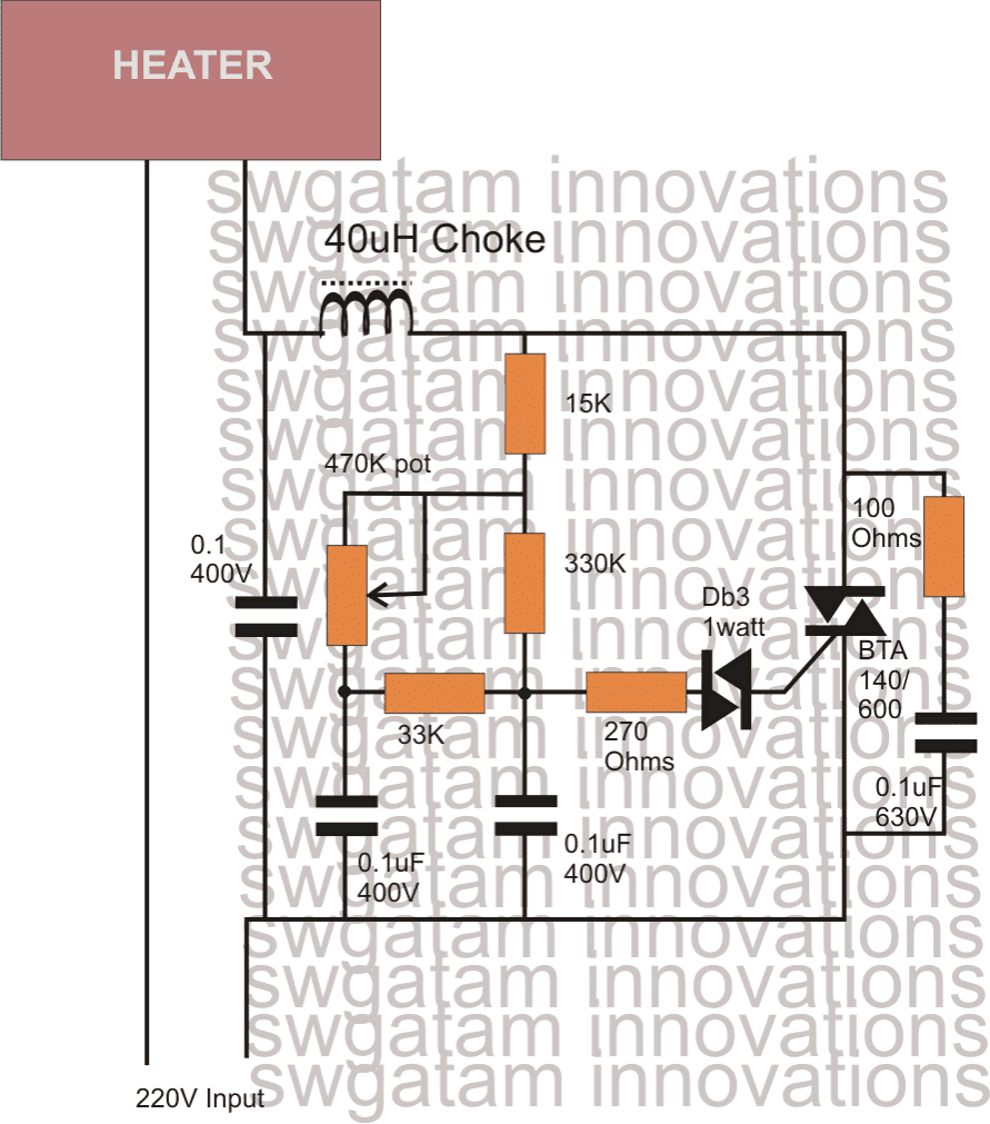
Circuit Description
The following simple thermistor based temperature indicator does exactly this.
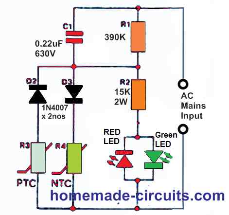
The value of R3 is low and that of R4 is high at a comparatively low temperature. During the positive half cycle of the mains voltage, there will be a voltage across R3-D3 that is high enough to illuminate the green LED.
The value of R3 is set to ensure that the voltage across it is very small to cause the red LED to illuminate during the negative half cycle of the mains voltage.
When the temperature rises, the value of NTC thermistor R4 decreases while the value of PTC thermistor R3 increases.
Eventually, the green LED illuminates with less and less brightness, while the red LED will starts lighting up with greater and greater brightness, until just the red LED is totally illuminated.
The current drawn by the LEDs is kept under control by resistor R2 and capacitor C3. This approach minimizes dissipation to a minimum.
Both R3 and R4 should be of fair size, with a diameter of at least 6 mm and no less.
The NTC thermistor must have a value of 22 to 25 k and the PTC thermistor must have a value of 25 to 33 Ohms at 25 °C. Because it conducts the entire mains voltage, the circuit should be handled with caution.
3 LED Temperature Indicator using a Single NTC Thermistor
This simple circuit allows you to instantly know if the temperature at a given location is within the expected range.
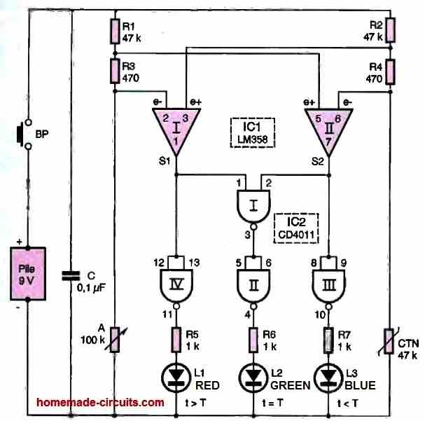
The device's interpretation is clear and straightforward: a green LED indicates conformity, a blue LED indicates a temperature below the required value, and a red LED indicates a temperature above the required value. The device is portable and easy to use.
Equilibrium situation
As an example, let's take the case of a reference temperature of 22.5°C.
For this value, the ohmic resistance of the NTC (Negative Temperature Coefficient Resistance) is equal to its marked value, namely 47 K Ohm in the present use.
Let's calculate the value of the potential at the positive terminal of the NTC.
U1 = [RNTC / (R2 + R4+ RNTC)] x 9 V
We obtain a potential of 4.478 V.
In an equilibrium situation, the adjustable resistor inserted in the other branch (which is perfectly symmetrical, by the way) of the circuit is also set to 47 K Ohm.
Let's now calculate the value of the potential available at the direct input (non-inverting) of the operational amplifier IC1.
U2 = [R3 + A / (R1 + R3+ A)] x 9 V
The value obtained is 4.522V. Considering the situation of the operational amplifier IC II, we can observe that the value of the potential available at the direct input is higher than that of the inverting input.
This results in a high state on output 7 of this operational amplifier.
The situation is exactly the same for operational amplifier I, whose output 1 also presents a high state. This has the following consequences:
- a low state on the output of the NAND gate III, and therefore the red LED L1 is turned off.
- a low state on the output of the NAND gate IV, and therefore the blue LED L3 is turned off.
- a low state on the output of the NAND gate I, and therefore a high state on the output of the NAND gate II and the green LED L2 is turned on.
The temperature decreases. When an NTC is placed in a thermal environment at decreasing temperature, its ohmic resistance increases.
Compared to the previous equilibrium state, this temperature decrease results in an increase in potential:
- at the direct input of operational amplifier I.
- at the inverting input of operational amplifier II. If the temperature difference is sufficient (we will come back to this), a new equilibrium situation is established.
- For operational amplifier I, nothing changes: the direct input remains subject to a higher potential (which has even increased) than the inverting input.
- The output 1 continues to present a high state.
- However, regarding operational amplifier II, the inverting input reaches a potential higher than that of the direct input. The output 7 switches to a low state.
- It can be verified that in this new situation, LEDs L1 and L2 are turned off while only the blue LED L3 is on.
As compared to the initial equilibrium situation, the ohmic resistance of the NTC decreases as the temperature increases, and it is easily observed that in this case:
- the output 1 of amplifier I switches to the low state
- the output 7 of amplifier II remains in the high state. This results in the extinction of LEDs L2 and L3. Only the red LED L1 remains lit.
Sensitivity of the device
With the resistance values used, for a given temperature and confirmed by the required position of the adjustable A cursor, the green LED remains lit as long as the difference does not exceed 1°C.
If a greater sensitivity is desired, it suffices to decrease the values of resistors R3 and R4. For example, by choosing 220 ohms, the circuit already reacts to a difference of about half a degree.
Conversely, if a lower sensitivity is preferred, the values of the same resistors should be increased. For 750 ohms, the device reacts only to a variation of about 1.5°C.
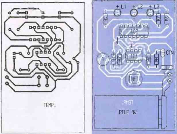
Construction
The first figure below shows the very simple printed circuit board of this circuit. It does not require any particular comments.
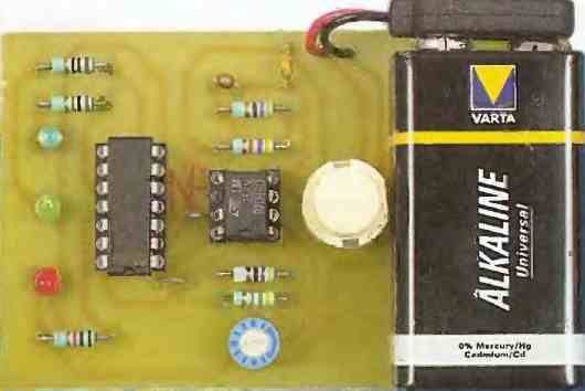
The second adjoining figure below shows the component layout plan. Note that the battery was directly glued to the module. Pay attention to the polarity.
The circuit does not require any particular adjustment. It is sufficient to set the adjustable slider to the required position. In practice, the method to be used is very simple.
When a room temperature is at the adopted reference temperature (which can be checked using a thermometer), it is necessary to slowly turn the adjustable slider in one direction or the other to obtain the stable position corresponding to the lighting of the green LED.
Circuit Diagram
Very Simple Temperature Indicator using a Meter
The following post explain how to build a simple temperature indicator using a 1 mA moving coil meter and a few transistors and resistors. The sensor device in this project is the diode 1N4148.
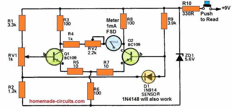
How it Works
In the above temperature meter circuit, a 1N4148 diode is employed to sense the temperature.
The 1N4148 diode's negative temperature coefficient corresponds to a scale of 2 mV/°C, and this voltage is detected in our circuit by differential amplifiers Q1 and Q2.
The diode might show an offset voltage of around 0.55 V. The offset voltage reading on the meter is corrected by adjusting the RV1 preset.
To prevent temperature-related changes in transistors from affecting the calibration, a differential amplifier is utilized.
It is advised that a push-to-ON button is employed to turn on power in order to save battery life since there is no device warm-up period in this circuit.
During the time the meter is functioning, the battery drains at around 10 mA; thus, if an uninterrupted reading is necessary, a modest power source must be incorporated.
Specifications
- Temperature Range: 0-100°C
- Sensor: Silicon diode 1N4148 ir similar
- Scaling: Mostly linear across a range of 0-100°C
How to Calibrate
Calibrating the meter involves a two-point process, utilizing the temperatures of melting ice and boiling water as reliable reference points.
To begin, immerse both the diode sensor and the thermometer in melting ice and fine-tune RV1 until the meter displays 0°.
Subsequently, insert the sensor into boiling water, ensuring a suitable container such as a kettle that partially confines steam is used, and then adjust RV2 until the meter reads 100°.
It is essential not to employ an electric jug with an exposed heater element during this process.
Alternatively, if a known ambient temperature is preferred as the low reference point, you can start by adjusting RV1 to make the meter read 0° with the sensor at the ambient temperature.
Then, with the sensor placed in hot or boiling water, adjust RV2 to ensure the meter displays the temperature difference accurately.
Once the sensor returns to ambient temperature (allowing time for cooling), readjust RV1 to display the actual ambient temperature.


Questions & Answers
sir,good night you are discussing about a capacitor with 15k resistor in above 1st circuit but there is no any capacitor in the circuit if there is any capacitor connected the where it to connect
Atul, the C1 is the capacitor…
Sir, mujhe ntc aur ptc ka number Jo component ke upar Diya hota hai please woh send kar dijiye
Ashu, the values are already given in the article.
Atul,
The NTC thermistor must have a value of 22k to 25 k and the PTC thermistor must have a value of 25 to 33 Ohms at room temperature.
sir,, it’s my humble request to you that I did not understand the value of ptc and ntc in above circuit.please reply me some solution for this.
Atul,
The NTC thermistor must have a value of 22k to 25 k and the PTC thermistor must have a value of 25 to 33 Ohms at room temperature.