The circuit I have I have explained in this article allows one to detect the current consumed by a device and to power one or more other devices accordingly. Indeed, the solution of a switchboard is not always applicable because it is often not very practical. Furthermore, some devices such as computers only start when their power button is pressed, and remain inactive when connected to a 220 V power supply alone. This type of device can be used to control the activation of other devices through this circuit. The circuit has one input and three outputs. The "master" device is connected to the first output, and when it is turned on, it activates a relay which triggers the power supply to the second output, while the third output stops being powered. This last function may only be suitable for very specific cases, but the relay used has a normally open contact which it would be a shame not to make available. By: Dan Russel
Circuit Description
The circuit diagram of the current detector switch is shown in the figure below. The 220 V AC input is connected to the card's input E. In parallel with this input is the primary of the power transformer of the card, whose secondary delivers 12 V (two windings of 6 V each in series).
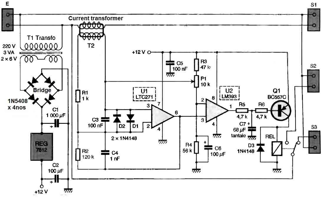
After rectification and filtering, the supply voltage is stabilized by a type 7812 regulator. The 220 V present at the input is directed to output S1 by passing through the primary of a rudimentary transformer used as a current sensor transformer.
When a current flows through the primary of this transformer, a voltage is generated at the ends of the secondary, the amplitude of which will be all the greater as the primary current is higher.
In order to obtain good sensitivity of the system, i.e., the ability to detect a low current, this voltage is strongly amplified by means of the operational amplifier noted U1.
Diodes D1 and D2 play a role in protection by clamping the input voltage in case of high surges that could occur at the primary of the transformer.
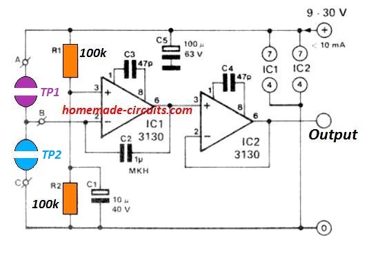
The presence of capacitors C3 and C4 limits amplification to low frequencies. In fact, the circuit should only react to the 50 Hz AC component, by prohibiting any untimely triggering due to possible high-frequency disturbances.
The amplified voltage, available at the output of the amplifier on pin 6, is applied to the non-inverting input of a voltage comparator noted U2 in the diagram.
The inverting input of this comparator is set to half the supply voltage, thanks to the voltage divider formed by R3, P1, and R4, a resistor decoupled by the electrolytic capacitor C8.
The offset adjustable by the potentiometer P1 allows adjustment of the triggering threshold and therefore the sensitivity of the circuit.
In the presence of a current in the primary of transformer T2, a rectangular signal with a period of 20 ms and an amplitude ranging from 0 to 12 volts will be observed at the output of the comparator on pin 1.
In fact, only the negative alternating cycles present at the input of the amplifier U1 cause the comparator U2 to switch, and consequently the transistor Q1 to conduct, leading to the closure of the relay.
The capacitance of C2 not only prevents the relay from opening between two negative alternations but also provides the necessary timing to avoid stressing the device controlled by too frequent on/off cycles in the case of a threshold setting that is too close to the limit.
How to Build the Current Transformer
The proposed mains AC current detector switch Circuit requires a current transformer. It consists of winding 5 turns of flexible wire with a section of 2.5 mm² as primary, and 50 loose turns of enamelled wire with a diameter of 35/100 as secondary, on a toroidal core that is nothing but a… soft iron washer with an outer diameter of 20 mm and an inner diameter of 10 mm.
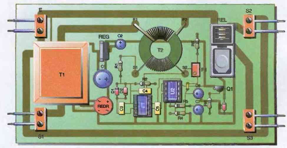
As can be seen from the model photo, this realization does not require particular care. However, care must be taken not to damage the insulation of the flexible wire used for the primary winding when winding it on the washer.
One should also be careful in the choice of the magnetic properties of the material of the core. This can be checked with a simple permanent magnet.
A wise precaution will then be to spray insulating varnish on this "transformer" in order to fix the windings. The input and output of the board can be made with printed circuit terminal blocks with a pitch of 7.5 mm.
Another possibility, as chosen for the model proposed here, is to use simple connected wire connectors, on the board side, with rigid bare wire segments.
The printed circuit tracks carrying the 220 V can be generously widened to avoid overheating in case of high current.
How to Test and Setup
Initially, potentiometer P1 will be set to the minimum position, and the devices will be connected to the board, but only the device connected to output S1 will be switched on.
The relay should then be in the closed position, and this can be verified by measuring 220 V at output S2.
Slowly turn the potentiometer clockwise until the relay releases: the current consumed by the load is then no longer sufficient.
Gently move it back to obtain the relay's closure again, and continue to turn the potentiometer one or two turns.
Check that when turning off the "master" device, the 220 V on output S2 disappears, while it returns to output S3. The board is now set up, and the control devices can be turned on.
Be careful of the sum of the currents consumed by the loads: it must not exceed the maximum current accepted, in particular, by the relay contact (10 A in the case of the relay used in this project).
WARNING !! Like any circuit directly connected to the mains, it is essential to have a permanent obsession with not touching the elements and copper tracks carrying the potential of 220 V. Before disconnecting the board, it is essential to ensure that it is placed on a clean insulating surface and that no metallic piece is lying underneath, such as a component leg, for example.
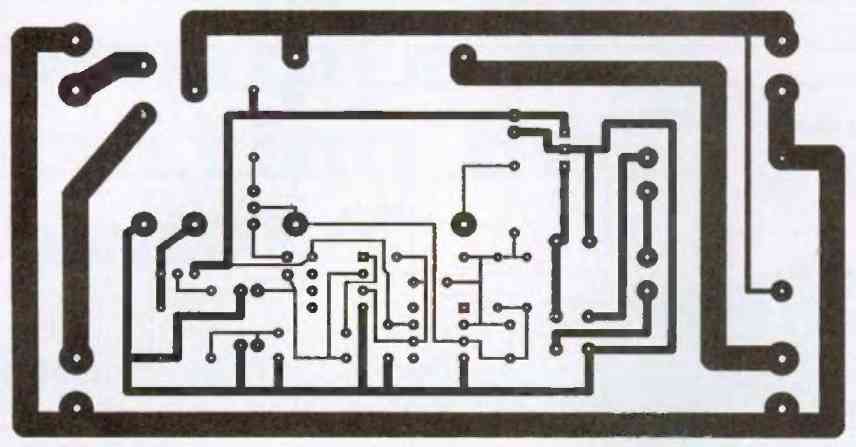
PCB Designs

Questions & Answers
hi, how did you draw the part side drawing? very handsome!
Hi, thanks for your feedback, actually it is not drawn by me, it was contributed by an external author.
Hi. I have two questions?
I have been looking for the LTC271 IC. It doesn’t seem to exist. There is a TLC271 instead. Is that?
Can the transformer be 220V – 12V and not 200V – 6V+6V?
Hi, Yes TLC271 can be used and a 0-12V transformer can be also used, I cannot find any issues with these two replacements.