This LED light bar with dimmable feature will allow the user to adjust the brightness of the lamp in 4 steps, with100%, 50%, 10% and 0% illumination control at each subsequent steps.

The idea was requested by one of the avid readers of this blog. Here's the required working concept.
Hi Swag !
I stumbled across your web page whilst searching for a solution to make an effective touch led lamp.
Actually the one my dad uses at night has gone kaput. So I thought why not make him one - being an engineer in the past.
NTE’s touch dimmable led light bar. I love how it’s built and I’d like to use this as a ref to make a night lamp for my dad whose old and needs it at night….
I intend to may be use a dimmable Led bulb or a led strip to make the lamp.
If you can help me with the circuit and maybe a tutorial sort as I’ve been out of this for a long time, it would really mean a lot.
Monish
The Design
The basic design of the proposed touch dimmable LED light bar circuit can be seen in the block diagram below:
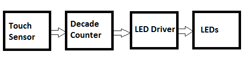
The touch sensor converts the tiny finger touch signal into amplified electrical pulses. The next decade counter stage converts these pulses into shifting logic levels across its outputs.
These shifting logic pulses are fed to the corresponding LED drivers which convert these signals into a sequentially varying voltages for the LED stage.
The varying voltages from the transistor stage which are set at specified levels cause the LEDs to illuminate with different light levels or brightness., accomplishing the dimmable effect on the LEDs.
How the Circuit Works
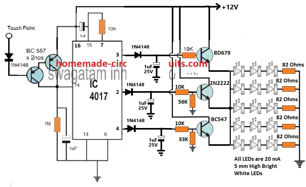
Referring to the circuit diagram above, the basic circuit functioning could be understood with the help of the following points:
The two BC557 transistors at the left side of the diagram form the touch sensor stage.
Tiny electrical pulses from the finger are amplified to the supply level and applied to the clock input of the IC 4017.
The IC 4017 is a 10 stage divide by 10 Johnson decade counter, which responds to these input signals and converts them into a shifting HIGH logic across its output pins from 3 to 4.
Initially when the circuit is powered, the 1uF at pin15 of the IC resets the IC so that the HIGH logic is set at its first pin out #3.
Due to this the corresponding BD670 transistor stage conducts and illuminates the LED array brightly. The BD670 being a Darlington device illuminates the LEDs with high brightness.
At this stage the brightness of the LEDs is maximum also because the BD670 has no potential divider at its base configuration.
This allows it to deliver an optimum 11 V from the 12 V supply to the LEDs at full current, illuminating the array with full brightness.
When the touch sensor is touched, the decade counter responds and causes its output logic to shift from pin#3 to pin#2.
This shuts off the BD670 stage and powers the pin2 transistor stage which is also wired like an emitter follower.
Therefore, now the 2N2222 transistor becomes responsible for illuminating the LED array.
However, since the base of the 2N2222 emitter follower is rigged with a potential divider that creates around 10 V at its base, causes the emitter of the 2N2222 to have a decreased emitter voltage, at around 10 V.
The 1 V reduction of the supply to the LEDs, decreases the illumination and dims the LED brightness to 50% less than the original level.
Next, when the touch sensor is touched again, shifts the HIGH logic from pin#2 to pin#4 of the IC. Likewise, now the BC547 driver stage activates and takes over the job of illuminating the LEDs.
But again, due to a potential divider at its base set to generate approximately 9 V output at the emitter, causes the LEDs to further dim at the lowest 10% of its original full level.
After this when the touch pad is touched, the clock signal at pin#14 of the IC shifts the HIGH logic from pin#4 to the next subsequent pin which is the pin#7.
However, since the pin#7 is attached with the reset pin#15, cause the IC output reset back to pin#3. This enables the LEDs to illuminate again with full brightness.
Thus means the dimmable tube light bar does not have a switch OFF step across the touch sensitive range.
If you wish to have the switch OFF function at the last stage, after the pin#4 step, you can achieve this simply by replacing the pin#7 with pin#10.
Meaning, pin#15 now connects with pin#10 via the 10K resistor. This will allow the 3rd touch action to switch OFF the entire LED bar, and the next subsequent touch will yet again restore the LEDs to its full brightness level.
Using Current Control for Dimming
In the above concept, the LED driver section dependent on a voltage controlled dimming on the LEDs.
In this concept the transistors are configured as emitter followers and their base voltages are controlled using potential dividers.
This allows their emitters to follow the base voltage and produce an equivalent controlled voltage for the LEDs.
This controlled voltage is appropriately calculated to generate the sequential dimming effect on the LEDs.
However, calculating and adjusting the base potential divider networks can be time consuming.
Therefore to make things easier we can simply convert the above voltage controlled dimming effect into a current controlled dimming effect, as depicted in the following diagram.
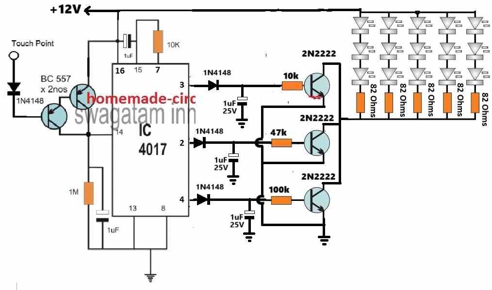
In the above configuration, the LEDs are shifted on the collector side of the transistors, and the base resistors are replaced with single resistors.
Here, the base resistors govern the collector current to the LEDs, which can be appropriately calculated for generating the desired sequential brightness control on the LEDs.
The following formula can be used for manipulating the base current for each of the transistors to illuminate the LEDs with a varied sequential brightness.
R = (Supply Voltage - Base/Emitter drop) x hFE / LED Current
Practical Example
In the above formula, the "R" represents the base resistors of the transistors.
Let the supply voltage be = 12V.
The base/emitter drop for a BJT is normally around 0.7V
The hFE of 2N2222 can be taken as 100.
Let's consider each LED to be rated at 20 ma, so each LED string with 3 series LEDs will also consume 20 ma. Since 5 LED strings are used, the LED current for generating maximum brightness on the LEDs will be 20 mA x 5 = 100 mA.
Therefore substituting the above values in our formula we get:
R = (Supply Voltage - Base/Emitter drop) x hFE / LED Current
= (12 - 0.7) x 100 / 0.1 = 11300 ohms
Thus a 11.3k resistor will cause all the LEDs to illuminate with maximum brightness.
Now, suppose we want the LEDs to illuminate with 50% less brightness on the second step. For this we have to reduce the LED current to 100/2 = 50 ma.
R = (Supply Voltage - Base/Emitter drop) x hFE / LED Current
= (12 - 0.7) x 100 / 0.05
= 22600
Therefore to illuminate the LEDs with 50% less brightness we have to select the base resistor of the second transistor as 22.6k
And so on, in this way we can generate the desired sequentially varying brightness on the LEDs, simply by changing the base resistor values of the transistors.


Comments
Good day Swagatam! I just want to ask, I’ve been able to produce a pcb out of this circuit, I tested and everything is fine but when I put in in the enclosure (which is a plastic enclosure), the sensitivity of the of the touch sensor is too weak to penetrate to the other side of the enclosure which has a thickness of 1mm. How should I modify the circuit to make it more sensitive? Does it do something about the resistance value on the touch sensor? Please give me an advice, Thank you!
Good Day Ryuchi,
The touch sensor requires physical touching with your finger, in order to toggle the IC and its outputs. If you do not touch the touch sensor pad directly with your finger then it will fail to detect the touch. In other words, there should not be a gap or a barrier between the touch plate and the sensor.
Please let me know if you have any further questions or doubts.
So I will not be able to trigger the sensor if i put it on the inside and touch it from the outside of the enclosure? Is there no way for me to adjust some values on the circuit which make the sensor detect a touch from the outside of the enclosure?
You can try increasing the touch plate area to around 1 sq inch and see if that solves the problem or not. Increasing the sensitivity too high can make the device prone to false RF triggering.
Alternatively, you can remove the IC 555 monostable section in your design and replace it with the following touch sensor module:
https://www.homemade-circuits.com/ttp223-capacitive-touch-module-explained/
Thank you!?
Good day Swagatam!
Just want to ask, for designing the pcb for this project, should i place the components the same as how i can see it on the schematic? Or is there a technique that i could use to arrange the components neatly with respect to the wirings. It’s my first time designing one and im not sure where and how to start. I’ve already get all the footprints but for the footprint for the LED Strips am not sure what to put. Hope to hear from you, thank you!
Good day Ryuchi,
For the above project there are no critical aspects that needs to be followed for designing the pcb layout, just make sure all the track connections are made correctly as per the diagram. You can terminate the transistor collectors through respective pads for implementing the external LED strip connections.
Thank you very much!
You are welcome.
Hi Swagatam!
I’ve already built the circuit for the 555 timer and integrate it to the IC 4017. But it doesn’t seem to fix the switching (i still used the open wire as the touch point), i looked at the diagram again and i saw that from the “touch point” on the original circuit, it became “touch plate”. May i ask what does it mean by the touch plate? And what material should i use for it and how is it different from the open wire used before? Thank you!
Hi Ryuchi,
Did you check the 555 monostable separately? Did the LED light up for 1/2 a second and switch OFF?
If it did and still not working with your 4017 circuit then 100% your 4017 is faulty or maybe it should be built by soldering.
The touch plate does not need to be a plate, it can be any small 1 inch open wire end.
Yes, on the 555 monostable circuit, the LED lights up when Im touching it and holding it, and turns off when i remove my hand from the contact. But after i integrate it with the IC 4017, it still jumps inconsistently and when i hold the touch point it constantly counts and not producing only one output. Should the 555 timer also eliminate the constant switching of light (when connected to the IC 4017)when i hold the touch point? If that’s how it supposed to work i think i really need to solder all the parts including the timer right? Thanks for answering my questions.
Sorry, that’s not the right way to check. The touching should be momentary, you touch for a fraction of a second and remove the touch, and the LED stays illuminated for 1 second and then automatically shuts off….this is the right procedure. This must happen on every subsequent momentary touches.
Please confirm the 555 operation as suggested above. You can increase C1 to 10uF or the 100k resistor to 1M to ensure the LED stays ON for at least one second before switching OFF automatically.
I see, so i need to expect a delay for the touch part. May i know what to expect too when the 555 timer is now integrated to the decade counter in terms of switching?
You can reduce the delay to 0.5 seconds by adjusting the C1 value. After integration, as you touch the touch point momentarily the output of the 4017 must sequence from one pin to the next without any fluctuations. Please let the LED/resistor remain connected so you can see the LED illuminate and turn off on each subsequent touch.
Good day Swagatam!
I have been troubleshooting the circuit for days on the breadboard. I tried increasing the capacitance on pin 14, removing the diode on the touch sensor, and such but the switching is still inconsistent and the led strips are flickering every after touch. It produces different sequence of outputs like after output 1 is output 3, in any random sequence. I know it’s not guaranteed to work properly on breadboard but is there a way to somehow make it work with the same schematic on breadboard? Cause i even checked for the voltage input of touch sensor with and without touch, it’s working properly. Even the voltages going through the ic are fine. Any advice you can give please? Thank you!
Hi Ryuchi,
To completely eliminate the switching bounce we may have to insert a 555 ic monostable between the pin14 of 4017 and the touch switch stage. I will draw the circuit and update it soon for you.
Thank you so much! Really appreciate it!
Ryuchi, Please build the following monostable circuit separately and check the response. You can reduce the C1 value to reduce the output ON time. I am sure the output of this circuit will correctly switch ON/OFF in response to the touches. Next, you can integrate the pin3 of this circuit with pin14 of IC4017
https://www.homemade-circuits.com/wp-content/uploads/2024/02/monostable-touch-switch.jpg
Hello again! I am now trying to build the circuit, i saw that the power supply of this circuit is 6V, should i use a LM317P voltage regulator to integrate it to pin 14? And the number 3 pin of the 555 timer should be connected to the pin 14 right? without the LED and resistor? If i put the voltage regulator, how should i connect it between the 555 timer and the IC 4017? Also, just curious of the capacitor values, what the difference of using the 10nf and 10uf on the circuit? Just wanna know how it works, Thank you!
Sure, you can try it, but please confirm the working of the 555 monostable circuit separately first. On each touch the LED should light up for a second and then shut off.
6V is not required, no 317 IC is required. You can use a common 12V for both the circuits, 4017 and the 555 both can work with 12V.
Yes pin#3 of IC 555 can be directly connected to pin#14 of IC 4017.
You can keep the LED also connected with pin#3 of 555 which will indicate the working each time the touch plate is touched.
The 10nF ensures the 555 is not affected by spurious stray RF disturbances. 10uF decides for how long the output (LED) stays ON when the touch plate is touched. The output ON delay can be adjusted by adjusting the C1, R2 values of the IC 555 circuit
https://www.homemade-circuits.com/wp-content/uploads/2024/02/monostable-touch-switch.jpg
Thanks! The 555 monostable circuit is working even though i used 1uF capacitors as a tester for the circuit but it gradually smells burning(capacitor) ahahah. Last question, should i still use the same value capacitors in the 555 circuit diagram even though the supply changes from 6V to 12V? Really thank you for your response!
In the following diagram, C1 value decides how long the LED stays ON before switching OFF. Please adjust the value so that the LED stays ON for half a second and then switches OFF, until again the touch switch is touched.
For 12V supply make sure the capacitor voltage ratings are minimum 25V and the LED resistor is 1K.
https://www.homemade-circuits.com/wp-content/uploads/2024/02/monostable-touch-switch.jpg
Thanks! So it will be the same capacitor values right? Which is better to use for this circuit, ceramic or electrolytic capacitor?
C1 is electrolytic, you will have to experiment with the C1 value, as explained in my previous comment.
C2 can be ceramic.
Just want to clarify, this ic 555 will eliminate the circuit of the two bc557 transistors right? If so, will a part of a circuit from the ic 555 be also connected to the vcc(just like the emitter of the bc557 from the original circuit) of the ic 4017, or just the pin14? And what should i expect for the indicator to happen because now i tried the 555 timer circuit with just a wrong capacitor since i only have 1uF here, and after i connect the supply, and touch once, it just keeps “On” (I used led strips as the indicator). Should i expect the indicator to turn off through some seconds or touch? Or it will keep turning on until the supply is removed? Sorry for lots of questions if I’m bothering you and also thank you for still answering my questions 🙂
Yes, the BC557 stage can be removed and replaced by the 555 circuit. The 555 circuit will share the same 12V supply which is used for the 4017 circuit.
The LED should turn ON momentarily and then turn OFF. If it stays ON that means something is wrong with your circuit for the IC.
Thank you very much! Really appreciate it!
Hi Swagatam! I already made the circuit work! Thanks a lot! Just kind of curious what is the purpose of capacitor connected from pin 15 to pin 16 and the capacitor connected in parallel with the 1M resistor? Thank you!
That’s great Ryuchi, Glad it is working now.
The capacitor across the positive and pin#15 ensures that whenever power is switched ON, the voltage momentarily enters through the capacitor and resets the IC through pin#15. This ensures that the output always starts from pin#3 and not from any other random output pin.
The capacitor at pin#14 ensures the pin#14 is not activated any spurious signal, rather only through a genuine positive signal. It also filters the pulsating signal generated by the touch sensor.
I tried to replace the maximum brightness output into 390ohm resistor and it’s producing at 11.30V something. Then i replaced the second output with a 390ohm also it now outputs 9V then the third one i didnt replace anything. Am i on the right track? Thanks!
You have to adjust only the base resistors of the 2N2222 transistors.
Yes ive adjusted the base resistors ?
Hi again Swagatam!
Just wanna ask about which is a good conducting wire to use as a touch sensor for the lamp because the switching of light output in every touch is inconsistent. Sometimes it switches and sometimes not. Mostly, the counter counts so fast especially when u lean your finger on the touch sensor. How can i make it consistently switching through every touch without leaning the press of my finger just to switch its output?
Also, as i checked the output of every brightness i noticed that the brightest has 10.4V something as an output then the next ones only has 7V something as an output which doesn’t produce much light as to compared to the theory. Should i replace some resistors connected to the output so I can adjust its output? Thanks!
Hi Ryuchi,
I have tested this touch sensor circuit and for me it working perfectly, and the output relay switched ON/OFF with every touch.
So inconsistent switching must not happen.
I hope you have connected all the parts exactly as shown in the last diagram correctly, and you are using a regulated 12V DC as the supply.
The sensor can be any 1 inch copper wire with an open conductive end where the touch is made.
You can try increasing the pin#14 capacitor to 2.2uF or 4.7uF and check the response.
If you wish to have an extremely accurate response without any bounce then you may have to include a monostable 555 circuit at pin#14 of the 4017 IC.
As far as the brightness of the LEDs is concerned it will solely depend on the base resistor of the transistors. You can adjust the values of the transistor base resistors and adjust the LED brightness accordingly.
May i ask what size of the wire(AWG) would you recommend? Because now im using breadboard not a pcb, should the wire fits perfectly through the hole of the breadboard? Cause that’s where i get the inconsistency of the touch. Thank you for answering again my questions. Really appreciate it!
I think on a breadboard the circuit might not work correctly, you must build the circuit on a strip board by soldering, only then expect it to work correctly, because each and every connection should be 100% perfect which cannot be guaranteed on a breadboard.
Good day Sir!
I already build the circuit but i can’t make the switching of brightness work. I’ve tried to use the diode and an open wire as a sensor but it doesn’t work no matter how many times i repeat it. I also tried some simple sensor circuits online to replace the touch sensor but it still didn’t work. Im not sure if the sensor circuit is the problem or the logic of the ic. Please help me to troubleshoot the problem. if in case the problem is the ic, how should i troubleshoot it to function its switching. Thank you.
Hi Ryuchi,
Are the outputs of the 4017 switching sequentially from pin3 to pin4? Please connect LED with 1k series resistor parallel to the 1uF capacitors (after the 1N4148 diodes) to check whether the outputs are sequencing or not.
Let me know about this.
The outputs are not switching, it stays on default
remove the BC557 transistors and connect the pin#14 intermittently to positive via a push button switch or manually, and check whether the outputs are sequencing or not.
Should i connect the positive side of the switch to the 12V?
Take a push button, connect its one terminal with pin14, and the other terminal with the positive of the. circuit. Pressing this switch alternately should cause the outputs to sequence from one to the next..
I tried it but it also didn’t work. Still the same circuit right?
That means your basic IC 4017 circuit is not working, which could be due to a faulty IC or some other connection fault.
The basic 4017 touch switch is a tested design you can find the article in the below given link. You will have to investigate the connections or try it with a new IC. Yes, all the 4017 touch switch circuits are based on the same principle.
https://www.homemade-circuits.com/simple-touch-sensor-switch-circuit/
I used 12V LED strips for the outputs so I don’t need to use resistors. Do i need to modify something on the circuit if i use led strips?
Yes, in that case no need of using series resistors. I hope you are using the last circuit.
Yes im using the last circuit not the current controlled. Im using 3 2n2222 transistors as the transistors for the output also
You are most welcome Ryuchi, glad I could help.
You can also find some more information in the article, I updated it recently.
Really thanks for giving me the response! I really appreciate it, sorry if i have lots of question. I just really want to grasp the concept of designing this circuit 🙂 Thanks!